S&B Filters 76-6000 User manual

15461 SLOVER AVE., FONTANA, CA 92337 | PH: 909.947.0015, FAX: 909.947.0603 | WWW.SBFILTERS.COM
P/N: 76-6000
INSTALLATION INSTRUCTIONS:

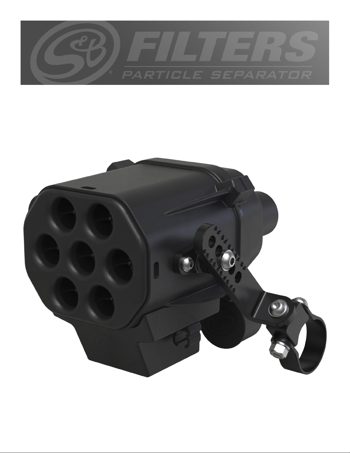
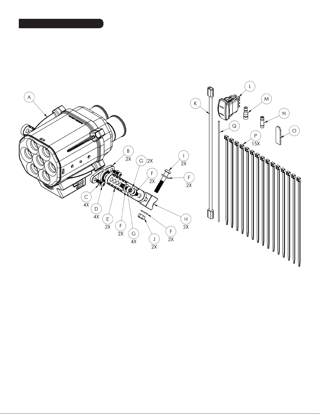
Thank You! for purchasing your new S&B Filters Helmet Particle Separator. If at any time you need additional assistance with installation or
have any other questions or comments, feel free to call our customer support team at 909-947-0015. You can also take advantage of our live chat
at www.sbfilters.com and connect with an S&B representative immediately. We hope you enjoy your new S&B Filters product and thank you for
your continued support.
THREAD LOCKER USE
We have provided a small tube of thread locker in your kit. Whenever
you see the symbol above on a step of the instructions apply 1 small
drop of the thread locker to the threads of the screws or bolts. This will
keep your hardware from vibrating loose during rough driving. If the
hardware ever needs to be removed, do so slowly to avoid having the
inserts strip out from the plastic.
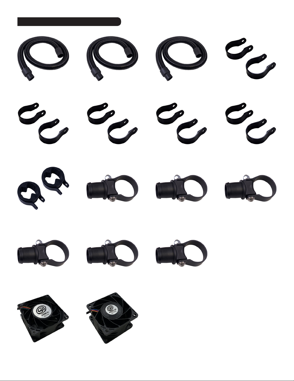
• Please read the entire product guide before proceeding.
• Ensure all components listed on pages 3 are present.
• If you are missing any of the components, call the S&B
Customer Support Team at (909) 947-0015.
• Disconnect your battery before doing any electrical
modifications.
BEFORE YOU START
2
THIS EQUIPMENT SHOULD BE INSTALLED, ADJUSTED, AND SERVICED BY PERSONNEL FAMILIAR WITH THE CONSTRUCTION
AND OPERATION OF THIS TYPE OF EQUIPMENT AND THE HAZARDS INVOLVED. FAILURE TO OBSERVE THIS PRECAUTION COULD RESULT
IN SEVERE INJURY. READ THIS MANUAL THOROUGHLY AND MAKE SURE YOU UNDERSTAND THE PROCEDURES BEFORE YOU ATTEMPT
TO OPERATE THIS EQUIPMENT. THE PURPOSE OF THIS MANUAL IS TO PROVIDE YOU WITH INFORMATION NECESSARY TO SAFELY OPER-
ATE, MAINTAIN, AND TROUBLESHOOT THIS EQUIPMENT. DO NOT USE THIS EQUIPMENT FOR ANY REASON OTHER THAN ITS INTENDED
PURPOSE. FAILURE TO FOLLOW THESE INSTRUCTIONS WILL VOID ANY WARRANTY. KEEP THIS MANUAL FOR FUTURE REFERENCE. THE
INFORMATION CONTAINED IN THIS MANUAL IS SUBJECT TO CHANGE WITHOUT NOTICE.
Product will intake and expel both air and loose materials with high force and velocity.
• Install product by affixing to the rear upper or rear lower roll bar and ensure the air inlet is not blocked.
• If using product with only one rider, place provided rubber cap over helmet air output port not in use. Failure to do so may result in
low pressure and low flow to the port that is in use. It will also lead to possible contamination of the clean air chamber resulting in a
greater chance of debris entering the connected helmet.
• Do not place face, hair, extremities, clothing, or other loose material in front of air inlet or outlet during use.
• Install product by affixing to the rear upper or rear lower roll bar to avoid placing hair, extremities, clothing, or other loose material in
front of air inlet during use.
Moving parts are sharp and could cause personal injury.
• Keep fan safety cages, blower outlet, and exhaust cover in place while operating and after service.
• Disconnect product from power source before servicing.
Product is designed to filter approximately 99% of solid particulate, such as dirt and dust. No filtration device is 100% effective, and
users may still experience distribution of dirt/dust within their helmet. To minimize this experience, ensure connection of the product to
user helmet at either of three locations. Directly on the helmet at the top right, top left, or top center ports. Connection of the product
to another location on the user helmet may increase the risk of use inhalation or eye exposure to dirt, dust, or other solid particulate
matter.
Product is designed for use in conjunction with an ATV’s operating manual, and state and federal law.
• Keep your seat belt fastened and wear a helmet while operating the vehicle.
Risk of electric shock!
• Improper installation, maintenance or operation could cause serious injury or property damage.
Periodically check the following:
• the Helmet PS exhaust fan and blower fan making sure they are working properly and blowing out air like when it was new.
• the fasteners of the Helmet PS assembly making sure they are tight and secured.
• the mounting brackets, straps and fasteners making sure they are tight and secured.
• the wire harness for any signs of wear making sure it is secured and away from any hot or moving components.
Important safety information and/or operating instructions for the end user might be included in this installation instruction sheet.
Make sure to give the instruction sheet included with this kit to the customer. Verify that the customer has access to all the information
required for proper use of the Helmet PS.
WARNING:

Order Online today at www.sbfilters.com or through your local S&B distributor.
RELATED ITEMS FOR YOUR PURCHASE
4’ Fresh Air Hose
SKU# HP1607-00
2.75” Straps
SKU# HP1606-00
6’ Fresh Air Hose
SKU# HP1608-00
8’ Fresh Air Hose
SKU# HP1609-00
1.5” Straps
SKU# HP1445-00
1.75” Straps
SKU# HP1393-00
1.5” Hose Hanger
SKU# HP1610-00
2.5” Hose Hanger
SKU# HP1614-00
1.85” Straps
SKU# HP1605-00
1.75” Hose Hanger
SKU# HP1611-00
2.75” Hose Hanger
SKU# HP1615-00
2” Straps
SKU# HP1446-00
1.85” Hose Hanger
SKU# HP1612-00
Blower Fan
SKU# AI2098-00
2.5”Straps
SKU# HP1604-00
2” Hose Hanger
SKU# HP1613-00
Scavange Fan
SKU# AI2102-00
3

EXPLODED VIEW:
3

4
PARTS LIST: 76-6000
ITEM QTY PART NUMBER DESCRIPTION HARDWARE PACKS
A 1 AL2008-00 HELMET PARTICLE SEPARATOR ASSEMBLY HP1603-00
AI1800-01
AI1781-01
AI1782-02
HP1390-01
AI2111-00
AI1802-00
AI2038-00
AI1736-00
AI1740-00
AI1416-00
AI1595-00
HP1581-00
AI2088-00
AI2078-00
AI1799-00
AI2004-00
AI2141-01
AI1750-00
HP1582-00
AM0450-00
B 2 AI1800-01 ADAPTER
C 4 AI1416-00 M6 SS FLAT WASHER
D 4 AI1802-00 M6 X 1.00 X 18 SS SCREW
E 2 AI1781-01 L-BRACKET
F 8 AI1740-00 M8 SS FLAT WASHER
G 4 AI2111-00 M8 X 1.25 X 22 SS SCREW
H 2 AI1782-02 PIVOT BODY
I 2 AI2038-00 M8 X 1.25 X 50 SS SCREW
J 2 AI1736-00 M8 X 1.25 NY-LOCK LOCKING NUT
K1AI2088-00 WIRE HARNESS
L1AI2078-00 ROCKET SWITCH
M 1 AI1799-00 POSI-TAP
N 1 AI2004-00 POSI-SEAL
O 1 AI1595-00 THREADLOCKER
P 15 AI1750-00 CABLE TIE
Q 1 AI2141-01 WIRE
AM0450-00 01/22/2019

5
INSTALLATION STEPS:
Determine where you want to mount the Helmet Particle Separator. The intake
can face forwards or backwards, but it needs to be mounted horizontally,
with the Exhaust Fan pointing straight down. It is recommended to mount
the Helmet PS in an orientation where there is less dust entering the vortex
separators. Also note the Fan Speed Knob is between the Helmet Ports.
1
Install the L Brackets (E) onto the Adapters with the Screws (G), Washers (F),
and Thread Locker (O), selecting the proper angle and orientation based on
the desired location for the Particle Separator, then tighten. Tool Needed: 5mm
Hex Key
3
Install the Pivot Bodies (H) with the Screws (I), Washers (F), and Locknuts (J).
Snug the straps up, but do not fully tighten, leave the straps loose enough so
they can be slid side to side and rotated. Tools Needed: 13mm Wrench, 5mm
Hex Key
5
Install the Adapters (B) onto the Helmet Particle Separator Assembly (A) with
the Screws (D), Washers (C), and Thread Locker (O), then tighten. Tool Needed:
4mm Hex Key
2
Slide the Straps (sold separately) over roll cage. Wrapping a small parts bag
around the roll cage will make sliding the strap over the roll cage easier and
help protect the roll cage from scratches.
4
Install the L Brackets (E) onto the Pivot Bodies (H) using the Screws (G) and
Washers (F), and Thread Locker (O), then tighten. Tool Needed: 5mm Hex Key
6

6
INSTALLATION STEPS:
Once you are satisfied with the position of the Particle Separator, tighten the
Straps, double check that all mounting screws and nuts are tight and that they
are securely mounting the Particle Separator on the roll cage. Tools Needed:
13mm Wrench, 5mm Hex Key
7
The Power, Ground, and Accessory Wire go to the corresponding posts of the
vehicle buss bar. If you don’t have a buss bar, the Power and Ground can go
to the battery, and the Accessory wire can go to a keyed power source. Use
the Posi-Seal (N) and Wire (Q) to extend the ACC wire and use Posi-Tap (M) to
connect to the switched power source.
9
Route the Fan Connectors up to the particle separator and plug them in. There
are 2 fans in the Helmet Particle Separator, the scavenge fan that separates
the dust, and the blower fan that forces fresh air into your helmet, the
connectors are identical.
11
Familiarize yourself with the Wire Harness (K). It has a red Power Wire
(BATT), a black Ground Wire (GND), an orange Accessory Wire (ACC), dual
Fan Connectors, and labeled female spade terminals for the supplied Rocker
Switch.
8
Cut a 13/16” by 1 7/16” hole in the desired mounting location for the Rocker
Switch. Use a file to slowly open up the hole for a precise fit. Plug the female
spade terminals into the corresponding male spades on the Toggle Switch.
Optional, if you choose to use your own 2 post switch wire #2 & #6 together on
one post, and #3 on the other post, then exclude #7 & #8 which are grounds.
10
Double check to make sure all connectors are plugged in and secured. Turn
the ignition and switch on and make sure air is blowing out the blower and
exhaust ports of the Particle Separator. If the exhaust fan does not turn on,
double check your electrical wiring. Your installation is now complete. Enjoy
your new Helmet Particle Separator!
12
Other manuals for 76-6000
1
Table of contents