Safety Precautions
4 S&C Instruction Sheet 661-500
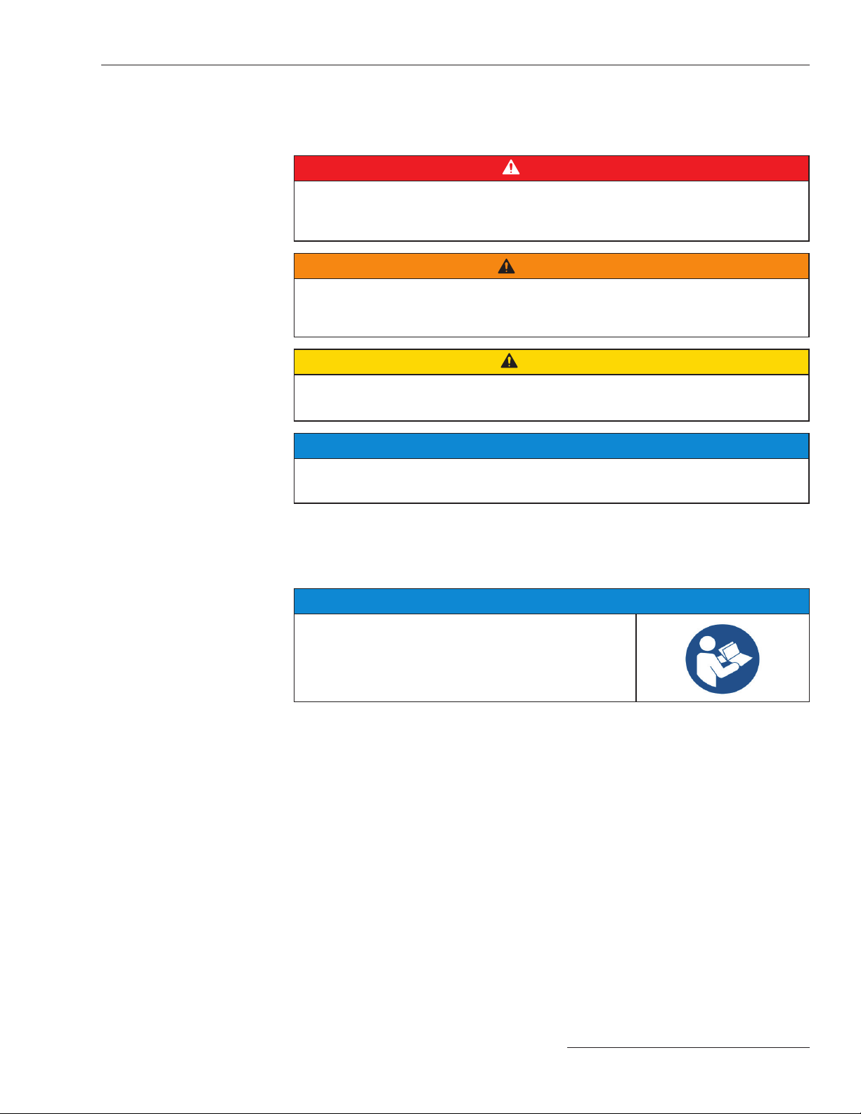
DANGER
Pad-mounted gear contains high voltage. Failure to observe the precautions
below will result in serious personal injury or death.
Some of these precautions may differ from company operating procedures and
rules. Where a discrepancy exists, users should follow their company’s operating
procedures and rules.
SAFETY INFORMATION CONTINUES ▶
1. QUALIFIED PERSONS. Access to pad-mounted
gear must be restricted only to qualified persons.
See the “Qualified Persons” section on page 2.
2. SAFETY PROCEDURES. Always follow safe
operating procedures and rules.
3. PERSONAL PROTECTIVE EQUIPMENT. Always
use suitable protective equipment, such as rubber
gloves, rubber mats, hard hats, safety glasses, and
flash clothing, in accordance with safe operating
procedures and rules.
4. SAFETY LABELS. Do not remove or obscure and
of the “CAUTION,” “WARNING,” or “DANGER”
labels.
5. KEY INTERLOCKS.
• If optional key interlocks were furnished, they
must be in place.
• Check the operating sequence of key interlocks
to verify proper sequencing.
• After the pad-mounted gear is installed, either:
(1) destroy the extra set of keys or (2) make them
accessible only to qualified persons. This will
maintain the integrity of the key-interlock
scheme.
• Key interlocks are not security locks and are not
substitutes for padlocks.
6. OPENING DOORS. Do not force doors open.
Forcing a door open can damage the latching
mechanism. If optional key interlocks are provided,
correctly position the interlocks so the doors can be
opened.
7. CLOSING AND LOCKING DOORS.
• Doors must be securely closed and latched, with
padlocks in place at all times unless work is
being performed inside the enclosure.
• Mini-Rupter® Switches have switch-operating
shaft access covers located on the sides of the
pad-mounted gear enclosure. They must be
closed and padlocked at all times unless the
switches are being operated.
• For PME pad-mounted gear, do not close a door
on a TransFuser™ Mounting in the Open
position with a fuse in the mounting. The door will
strike the fuse pull-ring, which will interfere with
door-closing. The door may be closed if the fuse
is removed from the mounting.
• For PMH pad-mounted gear, do not close a door
on a fuse in the Open position. The door will
strike the fuse pull-ring, which will interfere with
door-closing. The door may be closed if the
fuse is removed from the mounting.
8. ENERGIZED COMPONENTS.
• Always assume both sets of power terminals on
any Mini-Rupter Switch or fuse are energized
unless proved otherwise by test, by visual
evidence of open-circuit conditions on both sets
of terminals, or by observing both sets of
terminals are grounded.
• The Three-Phase Battery Charger contains the
following energized components:
— 300 Volts in pins 1 through 10 in the J3 connector.
— 30 Volts for the other wire connection terminals
(pins 11 through 20 in the J3 connector,
J2 connector, and J4 connector).
9. BACKFEED. Mini-Rupter Switches and fuses may
be energized by backfeed.
10. DE-ENERGIZING,TESTING,ANDGROUNDING.
Before touching any device to be inspected,
replaced, serviced, or repaired in the high-voltage
compartments, always disconnect Mini-Rupter
Switches and fuses from all power sources
(including backfeed), test for voltage, and properly
ground.
11. TESTING. Test for voltage on both sets of power
terminals of any Mini-Rupter Switch or fuse using
proper high-voltage test equipment before
touching any device that is to be inspected,
replaced, serviced, or repaired in the high-voltage
compartments.