Sandel SG102 Series User manual

Installation Manual
SG102
Attitude Heading Reference System
Including:
SG102/D (Digital)
&
SG102 MOD 2 with High Speed ARINC 429 and Reduced Initialization Time
&
MT102
Magnetic Transducer Accessory
Sandel Avionics, Inc.
2401 Dogwood Way
Vista, CA 92081
Phone (760) 727- 4900
FAX 760) 727- 4899
www.sandel.com
support@sandel.com

82011-IM, REV J Sandel SG102 & MT102 Installation Manual Page ii
[This page intentionally left blank]

82011-IM, REV J Sandel SG102 & MT102 Installation Manual Page iii
Table of Contents
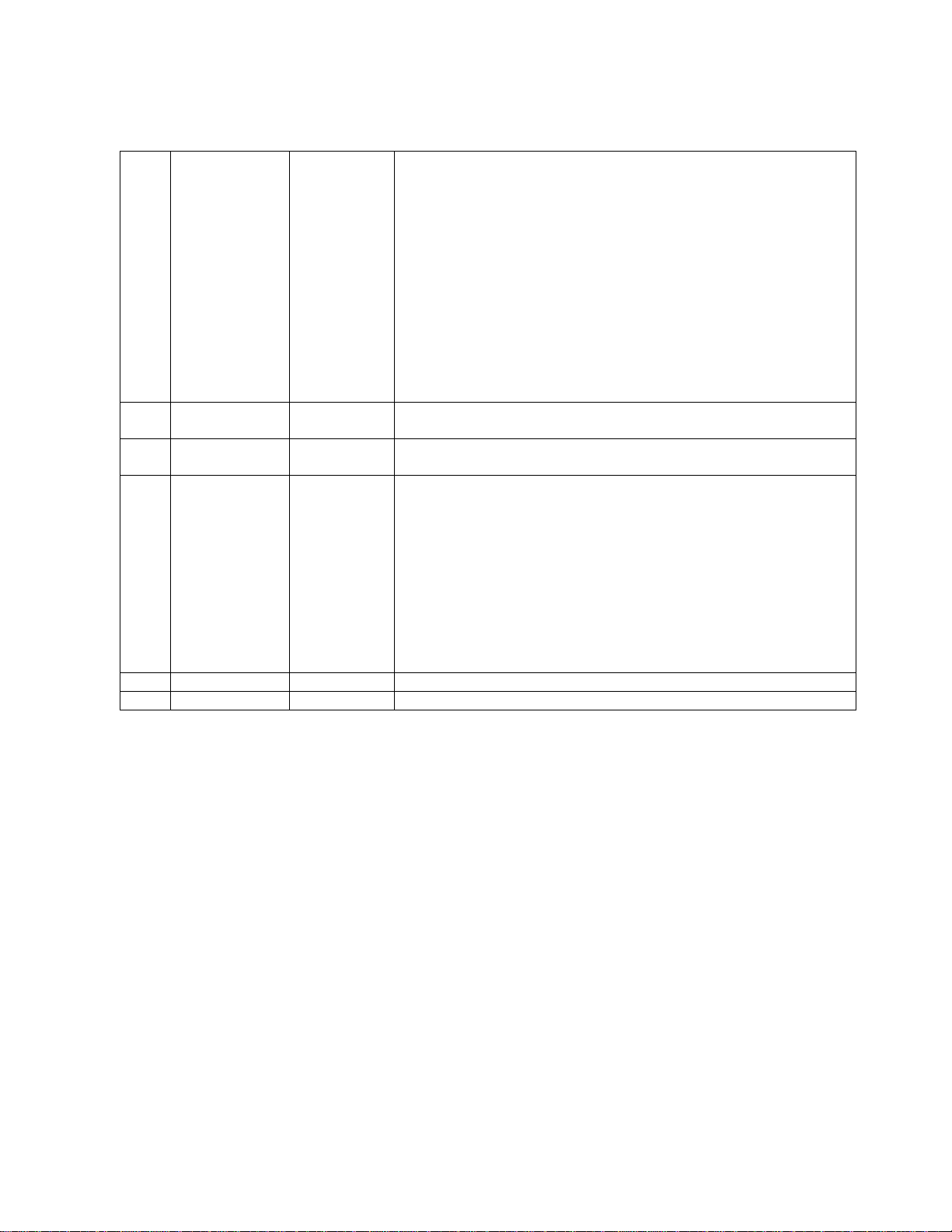
1General Information ...................................................................................................................1-1
1.1 Disclaimer...............................................................................................................................................1-1
1.2 Introduction............................................................................................................................................1-1
1.3 General Information on Strapdown AHRS..................................................................................1-2
1.4 SG102 Features....................................................................................................................................1-2
2Technical Information................................................................................................................2-1
2.1 General ....................................................................................................................................................2-1
2.2 MOD Levels............................................................................................................................................2-1
2.3 Part Numbers.........................................................................................................................................2-1
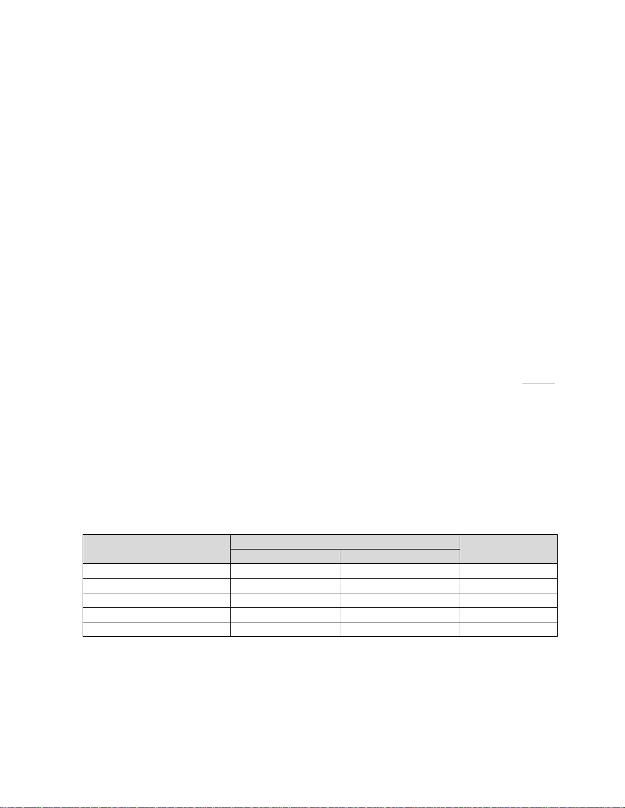
2.3.1 Software Version..........................................................................................................................2-2
2.3.2 Install Kit.......................................................................................................................................2-2
2.3.3 Bill of Materials – SG102 Install Kit...........................................................................................2-2
2.4 Approval Summary..............................................................................................................................2-3
2.4.1 License Requirements...................................................................................................................2-3
2.4.2 Approval Data...............................................................................................................................2-3
2.4.3 Technical Standard Order Stipulation..........................................................................................2-3
2.4.4 Installation and Operational Approval Procedures .....................................................................2-3
2.5 Characteristics......................................................................................................................................2-4
2.5.1 Dimensions....................................................................................................................................2-4
2.5.2 Summary Environmental.............................................................................................................2-5
2.5.3 Operational Specifications SG102 (MOD 2), SG102/D ............................................................2-5
2.5.4 Operational Specifications............................................................................................................2-5
2.5.5 Arinc 429 Labels – SG102 MOD 1.............................................................................................2-6
2.5.6 Arinc 429 Labels – SG102 MOD 2, SG102/D...........................................................................2-6
3Installation...................................................................................................................................3-1
3.1 Unpacking and Inspecting Equipment.........................................................................................3-1
3.2 Installation Planning...........................................................................................................................3-1
3.2.1 General Considerations.................................................................................................................3-1
3.2.2 Mounting Orientation...................................................................................................................3-1
3.2.3 Mounting Base Alignment...........................................................................................................3-1
3.2.4 Bendix/King KG102 Replacement Applications (SG102 P/Ns -000, -100, -200)....................3-1
3.3 Installation Considerations...............................................................................................................3-2
3.3.1 General..........................................................................................................................................3-2
3.3.2 Power.............................................................................................................................................3-2
3.3.3 Cooling..........................................................................................................................................3-3
3.3.4 Slaving Control Switches.............................................................................................................3-3
3.3.5 Operation without MT102............................................................................................................3-3
3.3.6 Inverter Outputs............................................................................................................................3-3
3.3.7 Synchro Outputs ...........................................................................................................................3-3
3.3.8 Discretes........................................................................................................................................3-3
3.4 Mounting Orientation..........................................................................................................................3-4
3.5 Attachment to the Airframe..............................................................................................................3-4
3.6 General Installation Instructions for the Hardware.................................................................3-4
3.7 Alignment................................................................................................................................................3-4
3.8 Post Installation Summary................................................................................................................3-6
4Connector Pinouts .....................................................................................................................4-1

82011-IM, REV J Sandel SG102 & MT102 Installation Manual Page iv
4.1 P-1 Connector......................................................................................................................................4-1
4.2 P-2 Connector (SG102 only)............................................................................................................4-2
5MT102 Information......................................................................................................................5-1
5.1 Differences between the MT102 and a Fluxgate........................................................................5-1
5.2 Environmental.......................................................................................................................................5-1
5.3 Wiring.......................................................................................................................................................5-1
5.4 Installation..............................................................................................................................................5-1
5.5 Connector...............................................................................................................................................5-2
5.5.1 Pinouts...........................................................................................................................................5-2
6Setup Procedures.......................................................................................................................6-1
6.1 Software Configuration......................................................................................................................6-1
6.1.1 SG102 Maintenance Adapter (USB) p/n 81032.........................................................................6-1
6.1.2 SG102 Installation-Calibration Utility Software.........................................................................6-1
6.1.3 Mounting Orientation Select........................................................................................................6-1
6.1.4 Compass Calibration.....................................................................................................................6-3
6.1.5 Arinc Maintenance Labels............................................................................................................6-3
6.1.6 Software Updating........................................................................................................................6-3
7Operational Details.....................................................................................................................7-1
7.1 Front Panel LED’s................................................................................................................................7-1
7.2 LED Error Codes..................................................................................................................................7-2
8Instructions for Continued Airworthiness...............................................................................
8-1
9Appendix A: Post-Installation Procedures.............................................................................9-1
10 Appendix B: Environmental Qualification............................................................................10-1
11 Appendix C: Sample FAA Form 337......................................................................................11-1
12 Appendix D: Sample Airplane Flight Manual Supplement..................................................12-1
13 Appendix E: Checkout Procedures.......................................................................................13-1
13.1 Functional Ground Test Procedures/Report........................................................................... 13-1
13.1.1 Introduction.............................................................................................................................. 13-3
13.1.2 Physical Installation................................................................................................................. 13-3
13.1.3 Wiring Verification and Initial Power-Up.............................................................................. 13-3
13.1.4 System Functions..................................................................................................................... 13-3
13.1.5 Installation Software: Mount Orientation Select.................................................................... 13-5
13.1.6 Installation Software: Heading Calibration............................................................................ 13-5
13.1.7 Additional Testing................................................................................................................... 13-5
13.2 EMI/RFI Test Procedures................................................................................................................ 13-5
13.2.1 NAV/COM Testing................................................................................................................. 13-5
13.2.2 General Testing........................................................................................................................ 13-6
13.2.3 Other Appliances..................................................................................................................... 13-6
13.2.4 Additional Testing................................................................................................................... 13-6
14 Appendix F: List of Effective Drawings and Attachments...................................................14-1

82011-IM, REV J Sandel SG102 & MT102 Installation Manual Page v
Table of Figures
Figure 3-1: Mounting base assembly features......................................................................3-5
Figure 3-2: SG102-0xx w/MOD 1, -1xx, -2xx, -3xx installed in Mounting Base Assembly....
................................................................................................................................................3-6
Figure 3-3 SG102-XXX w/MOD 2 installed in Mounting Base Assembly..........................3-6
Figure 3-4 SG102-X5X (SG102/D) installed in Mounting Base Assembly.........................3-6
Figure 5-1 MT102 showing alignment arrow......................................................................5-2
Figure 6-1 SG102 mounting orientations...........................................................................6-2
Figure 7-1 SG102 LED display..............................................................................................7-1

82011-IM, REV J Sandel SG102 & MT102 Installation Manual Page vi
Revision History
Rev
Date
Section(s)
Comments
J
29-SEP-2014
7.2
LED Error Code table updated.
H1
17 APR-2014
2.5.2
Summary Environmental table updated.
H 25-MAR-2014
ALL
1.2
1.4
2.2
2.3
2.3.3
2.5.1
2.5.2
2.5.3
2.5.5
2.5.7
3.2.3
3.2.4
3.3.2
3.3.6
3.3.7
3.7
4.1
4.2
6.1.2
6.1.4
7.2
12
14
SG102 MOD 0 not covered in this IM.
Added IM applicability statements.
Updated for high speed ARINC 429.Heading data output formats
updated.
MOD levels updated.
Additional part numbers added. Substitution note updated to include
SG102-x5x P/Ns.
SG102 Install Kit Bill of Materials updated.
MOD 1 & MOD 2 Length spec corrected (+.05” / excluding mating
connectors). Dimensions for SG102/D added.
Summary environmental data updated for SG102/D.
Summary Environmental data for MOD 1 & MOD 2 listed.
Updated for SG102/D.
Mounting base alignment note clarified.
Updated for applicability.
Section 2 references added.
Updated for applicability.
Images updated to include SG102/D.
Updated for SG102/D.
Updated for effectivity.
Updated for SG102/D.
Typo corrected.
LED Error Code table updated.
Updated for SG102/D.
List of effective drawings updated.
G2 6-FEB-2014
REV History
2.2
G1 section 2.4.2 reference changed to 2.5.2
Section 2.2: Mod Levels corrected.
G1 3-FEB-2014
2.5
2.5.2
2.2
14
Cover text updated.
ARINC Label table updated
Startup current updated to 30Watts, 1 minute
MOD Level description added
Added drawing 90183-05. Previously omitted.
G 30-JAN-2014
1.2
2.4.1
2.4.3
2.4.4
2.4.5
3.2.4
3.3.1
3.7
4.1
6.1.2
6.1.3
7.1
12
14
Limitations updated for MOD-2. Added note for recommended
maximum North and South latitude operation.
Updated for Mod 2
Updated for Mod 2
Initialization time and Arinc 429 info updated
Updated for Hi Speed Arinc 429. Rep rates updated
Added note for use as KG102 replacement when used with
SN3500/SN4500.
Updated for Mod 2
Mod 2 drawing added.
Updated for Hi speed Arinc 429
Mounting orientation drawings updated with MOD 2 SG102
SG102 LED Display image updated. MOD-2 Initialization time
added.
Mod 2 added to Sample AFMS.
List of Effective Drawings updated. Drawing 1071-05 Updated for
MOD 2

82011-IM, REV J Sandel SG102 & MT102 Installation Manual Page vii
Revision History
F 17-FEB-2011
1.3
2.2.1
2.2.2
2.4
2.4.3
2.4.4
3.3.8
4.2
5.4
6.1.6
Appendix B
Appendix D
Added note about 4-quadrant compass calibration. Updated Ground
Test references to Installation Software.
Updated installation program description.
Changed Install Kit text.
Updated mechanical specifications.
Added AHRS specs
Added new Arinc labels and selection info. Added 429 low speed
notes.
Added note on 10k pullup.
Added gnd/open to pin table
Added installation tolerance to MT102 longitudinal alignment.
Added reference to software loading.
Added DO-160E Environmental Qualification Forms.
Removed aerobatic limitation mod1.
E 11-FEB-2009 1.212
Update limitation note. Limitation, modified for reversionary or
backup display.
D 06-NOV-2008
7.1
12
Changed initialization time.
Changed sample AFMS section IV
C 30-OCT-2008
Cover
Rev History
2.2
2.2.3
2.4.1
3.3.1
3.7
7.1
12
13.1.4
14
Updated.
Format.
Added model number substitution notes.
Removed the –A from part numbers 84051 and 61251 on B.O.M.
Corrected dimensions and included MOD 1.
Changed installation drawing for MOD 1.
Modified Fig. 3-3 to cover SG102 with MOD 1.
Updated initialization time to include MOD 1 units.
Added MOD 1 initialization time to sample AFMS.
Added MOD 1 initialization time to ground test.
Updated drawing table, added note column.
B
07-FEB-2008
App. F
A/R 972 drawing 82011-10 sheets 4 & 5.
A
19-DEC-2007
All
Initial release.

General Information
82011-IM, REV J Sandel SG102 & MT102 Installation Manual Page 1-1
1General Information
1.1 Disclaimer
Sandel Avionics does not assume any risk for nor accept any responsibility for the interface
descriptions contained within this Installation Manual. It is the responsibility of the installer to ensure
that such equipment is compatible with the SG102 as described, and to ensure that the installation of
the SG102 is accomplished with such equipment using the specific equipment manufacturer’s
installation and technical instructions. No other representations are expressed herein.
1.2 Introduction
The Sandel model SG102 is a solid-state sensor that combines angular rate, linear acceleration and
magnetic field measurements to create an electronically stabilized strap-down Attitude and Heading
Reference System (AHRS).
The information contained within this manual describes the features, functions, technical
characteristics, components, approval procedures, installation considerations, setup procedures,
checkout procedures, and instructions for continued airworthiness for the SG102.
This revision of the SG102 Installation Manual is applicable to the following SG102 models:
SG102 MOD 1, SG102 MOD2. SG102/D.
For information pertaining to the SG102 MOD 0, please refer to 82011-IM revision G.
The SG102 requires the use of the Sandel MT102 magnetic transducer accessory. No additional flux
gate is used or required.
Limitation Notes:
(1) The SG102 is not certified to provide primary attitude information to the flight
crew. The SG102 is certified to provide reversionary attitude in the primary
field of view. The SG102 may also be used to stabilize other aircraft equipment
for example, RADAR and/or FLIR systems.
NOTE: The SG102 may not provide satisfactory heading performance above 70°
north latitude or below 70° south latitude.
The SG102 AHRS meets the pertinent requirements of
TSO-C4c “Bank and Pitch Instruments”;
TSO-C6d “Direction Instrument, Magnetic (Gyroscopically Stabilized)”
RTCA DO-160E
RTCA DO-178B, Level C Software

82011-IM, REV J Sandel SG102 & MT102 Installation Manual Page 1-2
1.3 General Information on Strapdown AHRS
When used as a DG replacement, the SG102 differs in certain key characteristics from the electro-
mechanical gyro it replaces which affect the installation. It must be remembered that the SG102 is a
strapdown AHRS and this means it is installed like an AHRS - even if it is used or thought of as a
directional gyro.
A strapdown AHRS is composed of three sensors in a Roll-Pitch-Heading orientation. When the
aircraft is level it is easy to visualize its operation as each of the three sensors senses the movement in
its own axis. However, the operation of the AHRS gets complicated as the aircraft maneuvers. For
instance in a 90 degree bank what was the Pitch sensor is now the Heading sensor; the Heading sensor
is now the Pitch sensor. This sensor translation occurs at every intermediate attitude. In order for this
process to work properly, the SG102 itself must be precisely aligned with the aircraft axis; otherwise
changes in roll may induce like small changes in pitch, and vice-versa. Very small misalignments will
wash out during operation, but large misalignments will cause improper operation.
A mechanical DG has no such requirement as it is gimbaled and will level itself to gravity on startup
and stay level during most flight maneuvers. This means that a mechanical DG installed non-level
will work properly; however installing with the SG102 without checking the mechanical alignment
will not work. Make sure the SG102 is mechanically aligned! Once correctly installed the SG102
mounting base is designed to allow removal and replacement of the SG102 without realignment.
The 4-quadrant compass calibration (part of the ground test procedure) is important for correct system
operation. Do this carefully! The benefit of doing this calibration correctly is the SG102 will be more
accurate in heading, especially during maneuvers, than a mechanical DG.
1.4 SG102 Features
The SG102 is intended for use in airplanes or helicopters to provide stabilized primary magnetic
heading to compass indicators, flight control and director systems, or other aircraft systems requiring
stabilized heading information.
The SG102 provides output heading data in the following formats:
Heading Format
SG102
SG102/D
MOD1
MOD2
ARINC 407 (XYZ)
X
X
-
ARINC 429 (LOW SPEED)
X
X
X
ARINC 429 (HIGH SPEED)
-
X
X
RS-232 Stormscope™
X
X
X
Quadrature Stepper
X
X
-
The SG102 incorporates a single 26 pin “D” connector with a Positronics latch. Additionally, the
SG102 MOD 1 and MOD 2 (P/Ns SG102-000, -100, -200) is signal and plug compatible with the
Bendix/King KG102 electromechanical directional gyro used in the KCS55 compass system.
Contact the factory with any questions about interfacing to specific equipment not covered in the
installation drawings.

Technical Information
82011-IM, REV J Sandel SG102 & MT102 Installation Manual Page 2-1
2Technical Information
2.1 General
The following section describes the technical characteristics that include the appliance approval basis,
physical and electrical properties, electrical connector pin allocation which details function and
gradient or equipment protocol, and ARINC label support. Also included is the description of the
SG102 and MT102 installation components, other equipment and installation requirements. A review
of the installation approval procedures is provided for filing with authorities.
2.2 MOD Levels
The SG102 models covered in this Installation Manual have been produced in several variations over
time: (As indicated on TSO label)
SG102 MOD 1
Shock Mount Base, Increased Roll Rate
SG102 MOD 2
Rigid Base. Provides High Speed ARINC 429, initialization time
is reduced.
SG102/D
Rigid Base. All digital.
MOD 1 and MOD 2 units are, except for the specifications, interchangeable.
2.3 Part Numbers
The part number (SPN) for the Sandel SG102 is:
Description
SPN - SG102 (MOD 1, MOD 2)
SPN - SG102/D
Fixed Wing, Piston Aircraft
SG102-000
SG102-050
Fixed Wing, Turbine Aircraft
SG102-100
SG102-150
Helicopter
SG102-200
SG102-250
SG102-XXX
Major
Variation
Minor
Variation

Technical Information
82011-IM, REV J Sandel SG102 & MT102 Installation Manual Page 2-2
The dash numbers differ in the environmental category certifications.
Note: The turbine models (-100, and -150) of the SG102 and the turbine model (-100) of the MT102
can be substituted for the piston fixed wing models (-000, and -050) of the SG102 and the piston
model (-000) MT102. The helicopter models (-200, and -250) of the SG102 and the helicopter model
(-200) MT102 can be substituted for either the turbine models (-100, and -150) or the piston models (-
000, and -050) of the SG102 and the MT102.
2.3.1 Software Version
The version number of software for the SG102 and MT102 is accessed by the Installation-
Calibration Software. See section 6.
2.3.2 Install Kit
2.3.3 Bill of Materials – SG102 Install Kit
Description
SPN
Fixed Wing, Piston Aircraft
MT102-000
Fixed Wing, Turbine Aircraft
MT102-100
Helicopter
MT102-200
All Variants
MT102-300
Description
SPN
SG102 Installation Kit
90171-IK
Description
SPN
QTY
Installation Software CD (includes Installation Manual)
82011-INCD
1
HD-26 Connector
32101
1
Plug, Circular Plastic, 9 Pin, Sealed
32097
1
Contact, Female – Size 16 Removable, 24-20 AWG
32099
9
Cable Clamp, Shell size 13 CPC
32100
1
Mounting Base Assembly
84051
1
Pan Head Machine Screw, 10-32 x .875
60220
4
Flat Washer #10
60221
4
Pan Head Machine Screw, 6-32 x .75 Brass
60222
3
Flat Washer #6 Brass
60223
6
Nut, Self-Locking 6-32 Brass
60224
3
Shim, Mounting Base
61251
6
Major
Variation
Minor
Variation
MT102-XXX

Technical Information
82011-IM, REV J Sandel SG102 & MT102 Installation Manual Page 2-3
2.4 Approval Summary
2.4.1 License Requirements
None.
2.4.2 Approval Data
Technical Standard Order: C4c, Bank and Pitch Instruments
C6d, Direction Instrument, Magnetic
(Gyroscopically Stabilized)
Software Certification: RTCA/DO-178, Level C
Environmental Categories: RTCA/DO-160E (Reference Appendix B)
2.4.3 Technical Standard Order Stipulation
The following stipulation as presented is required by the Federal Aviation Administration for
articles approved under Technical Standard Order. This statement does not preclude multiple
installation and operational approvals in regard to specific aircraft make, model, or type:
“The conditions and tests required for TSO approval of this article are minimum performance
standards. It is the responsibility of those installing this article either on or within a specific type
or class of aircraft to determine that the aircraft installation conditions are within the TSO
standard. TSO articles must have separate approval for installation in an aircraft. The article
may be installed only if performed under 14 CFR part 43 or the applicable airworthiness
requirements.”
2.4.4 Installation and Operational Approval Procedures
For the purpose of seeking installation approval, declarations should be made in the “Description
of Work Accomplished” section of a Federal Aviation Administration (FAA) Form 337 or other
field approval, or other limited supplemented type certification form. A sample Form 337 is
included in the Appendix. The basis of approval is for use as a gyroscopically stabilized
magnetic direction instrument. Applicable Federal Aviation Regulations (FAR) must be adhered
to.
The Environmental Qualification Forms for the SG102 and the MT102 is included in the
Appendix, and should be referenced to the categories appropriate to the aircraft type and
environment into which the system is to be installed. The environmental category for the AHRS
should be stipulated on the FAA Form 337, or other approval form.
A “Functional Ground Test Procedures/Report” and an “Operational Flight Check
Procedures/Report” is also included in the appendix, and should be used as a basis for validating
the SG102 equipment configuration and for verifying proper installation and functional
performance. A copy of this form should be submitted along with the FAA Form 337, or other
approval or certification form. A permanent copy must be filed and maintained by the installing

Technical Information
82011-IM, REV J Sandel SG102 & MT102 Installation Manual Page 2-4
agency. Another copy must be presented to the aircraft owner for entry into the aircraft
maintenance records, as well as a copy forwarded to Sandel Avionics along with the Warranty
Registration Form, Part Number 82011-0137, to be filed after completion and installation
acceptance. If any difficulty is experienced with the functionality or operational performance of
the SG102, contact Sandel Avionics for assistance.
2.5 Characteristics
2.5.1 Dimensions
SG102/D
Item
Dimension
Width:
5.0 in. (12.7 cm.)
Height:
2.53 in. (6.4 cm.)
Length:
6.3 in. (16.0 cm.) excluding mating connector
Weight:
1.65 lbs. (.75 kg.) including connector
CG:
2.54” from forward face, 1.1” from bottom of mounting
surface
SG102, MOD 2
Item
Dimension
Width:
5.0 in. (12.7 cm.)
Height:
2.53 in. (6.4 cm.)
Length:
6.3 in. (16.0 cm.) excluding mating connectors
Weight:
2.4 lbs. (1.08 kg.) including connectors
CG:
2.54” from forward face, 1.1” from bottom of mounting
surface
SG102, MOD 1
Item
Dimension
Width:
5.0 in. (12.7 cm.)
Height:
2.7 in. (6.9 cm.)
Length:
6.3 in. (16.0 cm.) excluding mating connectors
Weight:
2.8 lbs. (1.27 kg.) including connectors
CG:
2.54” from forward face, 1.22” from bottom of mounting
surface
MT102
Parameter
Value
Width:
3.37 in. (8.55 cm) - Diameter
Height:
0.95 in. (2.41 cm.)
Weight:
0.4 lbs. (.18 kg.)
CG:
@ Centerline, .25” below mounting face (excluding
cable/connector)

Technical Information
82011-IM, REV J Sandel SG102 & MT102 Installation Manual Page 2-5
2.5.2 Summary Environmental
2.5.3 Operational Specifications SG102 (MOD 2), SG102/D
2.5.4 Operational Specifications
* SG102 MOD 1 Only. See section 2.5.3 above for SG102 MOD 2 and SG102/D specs.
Parameter
SG102 (Mod 1)
SG102 (Mod 2)
SG102/D
Power Inputs
(Nominal)
15 watts 11 watts 8 watts
Startup Current
(11-33 vdc)
140 watts, 1 minute 20 watts, 1 minute 18 watts, 1 minute
Temperature
-55° C to +70° C
Altitude Up to 55,000 feet
Item
Spec
Body Rate Limits +/- 250 º/sec
Initialization Time Approximately 1 Minute, Standard day
ARINC 429 Low or High Speed
Item
Spec
Static Pitch and Roll Accuracy .35º typical initial; .2 º typical after 10 minutes
Dynamic Pitch and Roll Accuracy ±1º typical
Static Heading Accuracy ±1º typical after calibration
Dynamic Heading Accuracy ±4º during maneuvers
Body Rate Limits +/- 150 º/sec*
Body Acceleration Limits +/- 5g rms typ (see env. qual. category)
Aerobatics
Permitted, software version 1.25 and later. Aerobatic
maneuvers must be approx wings level 50% of the time
over any 5 minute period.
Turn Time Limits
Unlimited turn time (i.e. turns around a point), software
version 1.25 and later.
Initialization Time
Approximately 3 Minutes*
ARINC 429
Low Speed Only*

Technical Information
82011-IM, REV J Sandel SG102 & MT102 Installation Manual Page 2-6
2.5.5 Arinc 429 Labels – SG102 MOD 1
2.5.6 Arinc 429 Labels – SG102 MOD 2, SG102/D
*
Items with an asterisk are enabled or disabled during installation configuration. These items are
Sandel-specific binary labels intended for data recording and remote diagnostic purposes when
used with Sandel SN3500 and SN4500 series PNDs.
Label
Definition
Repetition Rate
155
Maintenance *
1 Hz
270 Discrete 30 Hz min
300 Compass Heading (averaged) 30 Hz min
320 Magnetic Heading 30 Hz min
324
Pitch Attitude
30 Hz min
325
Roll Attitude
30 Hz min
332 Body Lateral Acceleration 30 Hz min
350 Maintenance * 1 Hz
351
Maintenance *
1 Hz
352 Maintenance * 1 Hz
353 Maintenance * 1 Hz
354
Maintenance *
1 Hz
Label Definition
Repetition Rate
Low Speed High Speed
155
Maintenance *
1 Hz
1 Hz
270
Discrete
25 Hz min
50 Hz min
300 Compass Heading (averaged) 25 Hz min 50 Hz min
320 Magnetic Heading 25 Hz min 50 Hz min
324
Pitch Attitude
25 Hz min
50 Hz min
325 Roll Attitude 25 Hz min 50 Hz min
332 Body Lateral Acceleration 25 Hz min 50 Hz min
350 Maintenance * 1 Hz 1 Hz
351
Maintenance *
1 Hz
1 Hz
352 Maintenance * 1 Hz 1 Hz
353 Maintenance * 1 Hz 1 Hz
354
Maintenance *
1 Hz
1 Hz

Installation
82011-IM, REV J Sandel SG102 & MT102 Installation Manual Page 3-1
3Installation
This section provides information need to install the SG102 including interconnect diagrams,
mounting dimensions and information pertaining to installation.
3.1 Unpacking and Inspecting Equipment
Exercise care when unpacking the equipment. Make a visual inspection of the unit for evidence of
damage incurred during shipment. If a claim for damage is to be made, save the shipping container to
substantiate the claim. The claim should be promptly filed with the carrier. It would be advisable to
retain the container and packaging material after all equipment has been removed in the event that
equipment storage or reshipment should become necessary.
3.2 Installation Planning
3.2.1 General Considerations
The SG102 should be installed in accordance with standards established by the installing agency, and
existing conditions as to unit location and type of installation. However, the following considerations
should be considered before installing the SG102. The installing agency will supply and fabricate all
external cables when required. The required connectors and associated installation hardware are
supplied by Sandel in the Installation Kit.
3.2.2 Mounting Orientation
The SG102 supports various mounting orientations. See section 3.4 below. These orientations
provide flexibility in locating the position of the output connectors in relation to existing
harnesses.
Ensure that the 4 LED’s on the front of the unit are visible after installation.
3.2.3 Mounting Base Alignment
The SG102 is designed so that all aircraft alignments are made at the mounting base. After the
initial mounting base alignment the SG102 may be removed from the mounting base and
replaced without realignment.
3.2.4 Bendix/King KG102 Replacement Applications (SG102 P/Ns -000, -100,
-200)
When used as a directional gyro replacement for a Bendix King KG102 used in KCS55 compass
systems, with minor wiring modification the SG102 can be used to directly replace the KG102
DG and will drive a KI525 indicator with stepper-motor drive directly. The SG102 is designed
with the same legacy rectangular connector as the KG102 allowing easy retrofits.
In these applications the KMT112 fluxgate is removed and replaced with the Sandel MT102
magnetic transducer. The SG102 has an output which drives the KI525 in place of the original
KMT112 fluxgate. All other connections to the KI525 are retained and the SG102 drives all the

Installation
82011-IM, REV J Sandel SG102 & MT102 Installation Manual Page 3-2
original signals, including the flags and stepper motor pulses.
The KA51 slaving accessory is not required. However, it may be retained for the use of the
Slaving Switches and Slaving Meter, which will continue to operate. The slaving adjustments
are non operational and should be centered.
The SG102 is capable of operation during higher heading rates (up to 150 deg/s) than the KI525
indicator. If the actual heading rate exceeds 33 deg/sec, the SG102 limits the stepper pulses
issued to the KI525 to a maximum rate of 33deg/sec and keeps track of the dropped pulses.
When the aircraft rate slows down below 33deg/sec the missing pulses are re-inserted and the
KI525 is allowed to catch up to the correct heading. If at any time the KI525 compass card lags
the true heading in this fashion the KI525 HDG flag is asserted momentarily.
Note: When upgrading an existing installation from a
KG102 to an SG102 interfaced to either a Sandel
SN3500 or SN4500, you must remove connections
between the c, j, and n pins.
3.3 Installation Considerations
3.3.1 General
The SG102 installation should conform to customer requirements and airworthiness standards
affecting the location and type of installation.
For installation refer to Drawing No. 90171-05 titled, “Installation, SG102”, for specific
assembly and mounting instructions.
3.3.2 Power
Note that primary power is supplied on either P1 (26 Pin D) or the KG102 compatibility
connector (for P/Ns -000, -100, -200), but not both.
Please see sections 2.5.2 and 2.5.3 for Summary Environmental information.
The SG102 should be powered by the main bus or emergency bus (as appropriate). The SG102
is immune to transients and other anomalies which may be present on the main bus.
The SG102 requires 14vdc or 28vdc power
14vdc: 5.0A circuit breaker
28vdc: 5.0A circuit breaker.
Existing KG102 installations utilizing a 5amp circuit breaker may retain the 5amp circuit breaker
providing that the specific circuit breaker type can tolerate 5.0 amps for as much as 5 minutes
during startup.

Installation
82011-IM, REV J Sandel SG102 & MT102 Installation Manual Page 3-3
3.3.3 Cooling
No external cooling is required. The SG102 under normal operation will be warm to the touch.
3.3.4 Slaving Control Switches
In an existing Bendix/King replacement installation the KA51 slaving accessory may be used to
control the ‘slaving off’ mode. In new installations three switches may be installed if manual
slaving control is desired:
Slaving Off GND to operate; maintained
CW GND to operate; momentary
CCW GND to operate; momentary
NOTE: The SG102 may be installed with one set of slaving
switches only; either a KA51 connected to the 44 pin
rectangular connector, or new switches connected to the 26
Pin D connector.
3.3.5 Operation without MT102
The SG102 will not operate without the MT102 connected. Any application which requires
operation without a magnetic reference will not work with the SG102.
Note: The SG102 will not initialize unless it has
communication with the MT102. The SG102 will
flag if communication is removed from the MT102
3.3.6 Inverter Outputs
The SG102 contains an internal sine wave inverter. The inverter load is limited to 5VA, which
is sufficient to drive two synchro transmitters.
3.3.7 Synchro Outputs
The SG102 contains an XYZ heading output. The XYZ output is limited to 50ma and is
sufficient to drive two synchro CT’s.
Note: The XYZ output operates at a nominal 10.5v RMS. This output is compatible with any
Arinc 407 CT specified for 11.8V.
3.3.8 Discretes
The SG102 has Valid GND/OPEN and Invalid GND/OPEN discretes.
NOTE: Since these outputs are both GND/OPEN, if the receiving device does not pull
up to ACFT PWR, a 10K 1/2W resistor may be used between the discrete output and
ACFT PWR as a pullup source.

Installation
82011-IM, REV J Sandel SG102 & MT102 Installation Manual Page 3-4
3.4 Mounting Orientation
The SG102 may be mounted in different orientations to facilitate the installation. See section 6.1.3.
3.5 Attachment to theAirframe
The SG102 is designed to be rigidly attached to the airframe, the stiffer the better. Do not use any
shock mounts or other external parts.
3.6 General Installation Instructions for the Hardware
A. The installing agency will supply and fabricate all wiring harnesses when required. The length
and routing of wires must be carefully measured and planned before the actual installation is
attempted. Avoid sharp bends in the harness or locating the harness near aircraft controls. Observe all
recommended wire sizes and types and subscribe to appropriate FAR Parts 23, 25, 27, and 29, as well
as AC 43.13-1( ) and -2( ).
B. The use of MIL-C-27500 shielded wire and MIL-W-22759 single conductor wire is
recommended. The use of ferrules or grounding blocks for signal ground and digital ground returns is
satisfactory; however, each ground return must be electrically separated.
C. In order to ensure correct performance the SG102 and associated wiring must be kept at least a
minimum of three feet from high noise sources and not routed with cables from high power sources.
D. The pinout descriptions will assist you in determining installation requirements. Adhere to all
notes within these descriptions and on installation wiring diagrams.
E. Ground Bonding. In order to assure installation characteristics match the DO-160 RF and
Lightning test conditions, ensure that ground wires of at least the recommended size are installed in
accordance with the installation drawings and these wires are connected to a bonded aircraft ground.
F. Power Wiring. To assure that the SG102 will operate properly down to its rated minimum
input voltage of 11Vdc, ensure that power wires of at least the recommended size are connected from
the AHRS/DG circuit breaker to the SG102 in accordance with the installation drawings.
3.7 Alignment
The alignment process is performed as follows:
Step 1: Determine the aircraft leveling means. This information is noted either in the maintenance
manuals or may be found on the aircraft’s Type Certificate Data Sheet which can be found easily on
the FAA website. It is not necessary to actually level the aircraft – just know how to measure the tilt as
it sits.
Step 2: Where the SG102 is going to be mounted, make a sharp pencil line along the longitudinal axis
of the airframe. This can be accomplished by the use of a straightedge aligned square to a bulkhead or

Installation
82011-IM, REV J Sandel SG102 & MT102 Installation Manual Page 3-5
other transverse member. This line must be accurate – to within ¼ degree, which is easily obtainable
with hand tools.
Step 3: Take a small digital level and note the current lateral (roll) and longitudinal (pitch) tilt of the
aircraft as it sits, using the criteria determined in step 1. Make sure getting in and out of the aircraft
doesn’t change its position.
Step 4: Now shim the SG102 mounting base to reproduce the same pitch and roll tilt angle as the
airframe. Tighten the base mounting screws friction tight.
Step 5: Adjust the longitudinal axis of the mounting base so that it is parallel with the longitudinal axis
pencil line. Align Visually.
Step 6: Tighten the mounting screws. Make sure these are going into self-locking nutplates. The base
should be extremely stiff and shouldn’t slip.
Step 7: Install the SG102 into the base by sliding it into the rear hold-down, tighten the clamp, and
safety wire the clamp screws.
Figure 3-1: Mounting base assembly features
Mounting Screw
Holes
Rear Hold-down
Clamp
Clamp Screws
This manual suits for next models
4
Table of contents