S&S Cycle Stealth Air Cleaner Kit User manual

S&S®Cycle, Inc.
14025 Cty Hwy G
Viola, Wisconsin 54664
Phone: 608-627-1497 • Fax: 608-627-1488
Technical Service Phone: 608-627-TECH (8324)
Website: www.sscycle.com
Installation Instructions: S&S Stealth Air Cleaner Kit for
Harley-Davidson® Models with Milwaukee Eight® Engines
Instruction 510-0429A
04-02-2018
Version 1
© 2018
by S&S® Cycle, Inc.
All rights reserved.
Printed in the U.S.A.
IMPORTANT NOTICE:
Statements in this instruction sheet preceded by the following words are of
special signicance.
WARNING
Means there is the possibility of injury to yourself or others.
CAUTION
Means there is the possibility of damage to the part or motorcycle.
NOTE
Other information of particular importance has been placed in italic type.
S&S recommends you take special notice of these items.
WARRANTY:
All S&S parts are guaranteed to the original purchaser to be free of
manufacturing defects in materials and workmanship for a period of twelve
(12) months from the date of purchase. Merchandise that fails to conform to
these conditions will be repaired or replaced at S&S’s option if the parts are
returned to us by the purchaser within the 12 month warranty period or within
10 days thereafter.
In the event warranty service is required, the original purchaser must call or
write S&S immediately with the problem. Some problems can be rectied by a
telephone call and need no further course of action.
A part that is suspect of being defective must not be replaced by a Dealer
without prior authorization from S&S. If it is deemed necessary for S&S to
make an evaluation to determine whether the part was defective, a return
authorization number must be obtained from S&S.The parts must be packaged
properly so as to not cause further damage and be returned prepaid to S&S
with a copy of the original invoice of purchase and a detailed letter outlining
the nature of the problem, how the part was used and the circumstances at
the time of failure. If after an evaluation has been made by S&S and the part
was found to be defective, repair, replacement or refund will be granted.
ADDITIONAL WARRANTY PROVISIONS:
(1) S&S shall have no obligation in the event an S&S part is modied by any
other person or organization.
(2) S&S shall have no obligation if an S&S part becomes defective in whole or
in part as a result of improper installation, improper maintenance, improper
use, abnormal operation, or any other misuse or mistreatment of the S&S part.
(3) S&S shall not be liable for any consequential or incidental damages
resulting from the failure of an S&S part, the breach of any warranties, the
failure to deliver, delay in delivery, delivery in non-conforming condition, or
for any other breach of contract or duty between S&S and a customer.
SAFE INSTALLATION AND OPERATION RULES:
Before installing your new S&S part, it is your responsibility to read and
follow the installation and maintenance procedures in these instructions
and follow the basic rules below for your personal safety.
• Gasoline is extremely ammable and explosive under certain conditions
and toxic when breathed. Do not smoke. Perform installation in a well
ventilated area away from open ames or sparks.
• If motorcycle has been running, wait until engine and exhaust pipes
have cooled down to avoid getting burned before performing any
installation steps.
• Before performing any installation steps, disconnect battery to eliminate
potential sparks and inadvertent engagement of starter while working
on electrical components.
• Read instructions thoroughly and carefully so all procedures are
completely understood before performing any installation steps.
Contact S&S with any questions you may have if any steps are unclear or
any abnormalities occur during installation or operation of motorcycle
with an S&S part on it.
• Consult an appropriate service manual for your motorcycle for correct
disassembly and reassembly procedures for any parts that need to be
removed to facilitate installation.
• Use good judgment when performing installation and operating
motorcycle. Good judgment begins with a clear head. Don’t let
alcohol, drugs or fatigue impair your judgment. Start installation when
you are fresh.
• Be sure all federal, state and local laws are obeyed with the installation.
• For optimum performance and safety and to minimize potential
damage to carb or other components, use all mounting hardware that is
provided and follow all installation instructions.
• Motorcycle exhaust fumes are toxic and poisonous and must not be
breathed. Run motorcycle in a well ventilated area where fumes can
dissipate.
DISCLAIMER:
Many S&S parts are designed for high performance, closed course, racing
applications and are intended for the very experienced rider only. The
installation of S&S parts may void or adversely aect your factory warranty.
In addition such installation and use may violate certain federal, state, and
local laws, rules and ordinances as well as other laws when used on motor
vehicles used on public highways. Always check federal, state, and local laws
before modifying your motorcycle. It is the sole and exclusive responsibility
of the user to determine the suitability of the product for his or her use, and
the user shall assume all legal, personal injury risk and liability and all other
obligations, duties, and risks associated therewith.
Exempt from emissions tampering regulations on 2017-2018
touring models and 2018 Softail® models under
CARB EO# D-355-24

2
3. Install the three screws in the backplate as illustrated in Picture 4.
Picture 4
¼" - 20
Screws
Installed
NOTE: The screws will thread in with some resistance due to the slight
interference t of the threads in backplate.
4. Install the supplied o-ring in groove as illustrated in Picture 5.
A small dab of grease makes it easier to keep the o-ring in place
during installation.
Picture 5
5. Locate the two ⁄"-16 breather bolts and the eight rubber coated
washers. Put one washer on each breather bolt and pass through
the backplate mounting holes. Install another rubber coated
washer onto each breather bolt. As illustrated in Picture 6.
Backplate Mount
Breather Bolt
Rubber
Coated
Washer
Rubber Coated Washer
Picture 6
Picture 3
WARNING
•The safety of the motorcycle rider is dependent of proper
installation of this product. If you are not certain of your
capabilities or do not have the correct tools for this installation,
please consult a shop to have it done. Improper installation of this
product could result in injury or death to the rider.
•Be sure to disconnect the battery of your motorcycle before
starting on this procedure. Accidental starting of the motorcycle
could cause injury to you or others around you during the
installation.
Disassembly
Stock Air Cleaner Removal
1. Disconnect the negative battery cable from the motorcycle and
route it away from any metal parts in the area.
2. Remove the stock air cleaner cover and backplate assembly
following your service manual for the specic year and model bike
you are working on.
3. If equipped, remove the throttle body support bracket and plastic
wiring harness retaining clip. Picture 1 illustrates the bracket and
clip.
Picture 1
Plastic
Retaining
Clip
Support
Bracket
Installation
Installing the S&S Stealth AC Kit
1. Hold the electrical plug cover on the back side of the air cleaner
backplate with one hole over the locating boss. Fasten with the
#10-14 x .375" self-tapping screw provided, in the other hole. As
shown in Picture 2
Picture 2
2. Locate the three back plate screws. See Picture 3.
Kit Contents:
• Backplate
• Wiring cover
• Filter
• Filter Top Plate
• 243 Blue Loctite
• QTY of 3 - ¼" X 20
Backplate Screws
• QTY of 2 – ⁄" X 16
Breather Bolts
• QTY of 2 – ¼" X 20
Flanged Button
Head Screws
• QTY of 8 – Rubber
Coated Washers
• Electrical Plug
Cover Kit
• Cover Screw
• Backplate O-Ring
• CARB EO# Label

3
6. Apply a drop of 243 blue Loctite® to the threads of each screw and
breather bolt. Picture 7 illustrates all ve fasteners that require
243 blue Loctite.
Picture 7
Apply 243
Loctite®
7. Fit the backplate to the throttle body and the cylinder heads. Start
the threads of all the screws and tighten evenly until the backplate
is snug.
8. Now that the backplate is positioned, nish torque the ¼"-20
fasteners to 72 in.-lbs. as illustrated in Picture 8.
Picture 8
9. Check between the cylinder head and the backplate for air gaps.
NOTE: A feeler gauge works well for determining the amount of gap, if
any, between the head and the backplate as illustrated in Picture 9.
Picture 9
10. If a gap less than the thickness of a rubber coated washer is present,
torque the breather bolts down 10-12 ft.-lbs. If a gap of more than
the thickness of a rubber coated washer is present, determine
how much and select the appropriate number of rubber coated
washers needed to take up the gap.
11. If more than one rubber coated washer is needed between the
head and backplate, back out the breather bolts and install the
correct number of rubber coated washers.
12. Thread the breather bolts in and nish torque breather bolts to
10-12 ft.-lbs.
13. Locate the lter, plastic lter top plate and the two ¼"-20 anged
head fasteners as illustrated in Picture 10.
Filter Top Plate
Filter Flanged Head Screws
Picture 10
14. Apply a drop of 243 blue Loctite® to the threads of each ¼"-20
anged head screw and set aside.
15. Hold the lter on the backplate and put the lter top plate on top
of the lter making sure that the word “Down” is facing down and
sitting at on the lter and locked into the groove as illustrated in
Picture 11.
Picture 11
DOWN
16. Pass the ¼"-20 anged head screws through the plastic top lter
plate, thread in and tighten down evenly until snug and then nish
torque to 72 in.-lbs. as illustrated in Picture 12.
Picture 12
Torque to 72 in.-lbs.
4
17. Remove the ⁄" button head screw from the plastic top lter plate.
Picture 13 illustrates the button head screw.
Picture 13
5/16" Button Head Cover Screw
18. Attach an S&S air cleaner cover to the stealth air cleaner kit, and
fasten in place the ⁄" button head screw with 243 blue Loctite
appliedtothethreads. Torqueto 10ft.-lbs. AstockHarley-Davidson®
Milwaukee Eight® 2017-2018 Touring air cleaner cover may also be
installed, but Adaptor Kit #170-0352 is required for this installation.
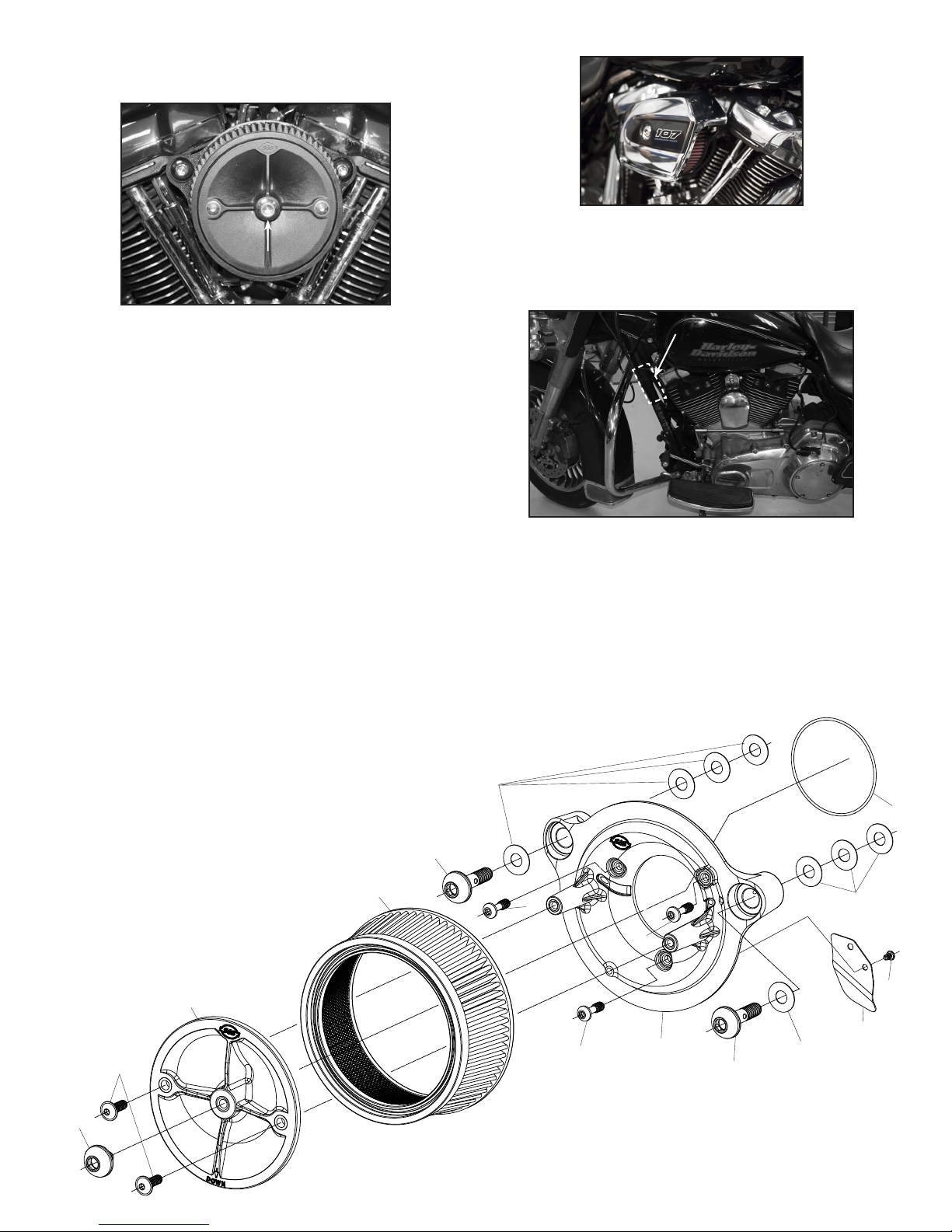
19. Apply the included label containing the CARB EO number to the
frame down tube above or below the factory label. Do not cover
up any portion of the factory label. See Picture 15
Picture 15
CARB label here
.
1
2
3
4
8
8
8
10
11
7
56
7
9
5
5
Picture 14 shows a Stealth kit with a stock cover
S&S Stealth Air Cleaner Kit for HD® Models with
Milwaukee Eight® Engines
1. Screw, SHCB, 5/16-18 x .500", Polished, Stainless Steel ......................500-0051
2. Screw, SHC, Flanged Button, 1/4-20 UNC x .750" (Each) ....................500-0060
3. Plate, Top, Air Filter, Molded, Plastic.......................................................... 170-0026
4. Filter, Air, Tapered, Standard Pleated,
5.500" x 6.000" x 2.375", Cotton....................................................................170-0126
5. Screw, SHCB, 1/4-20 UNC X .825" (Each) 3 required.............................500-0059
6. Backplate, Air Cleaner, Throttle-by-Wire, Stock Bore, Black,
Die Cast, M8 .........................................................................................................170-0353
7. Screw, Backplate Vent, SHCB, 3/8-16 x 1-1/2",
Polished,Stainless Steel (Each) 2 required............................................... 170-0045
8. Washer, Flat,.380" x .880" x .024", Nitrile Rubber Coated,
Cold Rolled Steel (Each) 8 required...............................................................50 -7054
9. O-ring, 2.75" ID x 2.875 OD, X 1 /16" Buna, (-039)................................. 50-8207-S
10. Cover,Electrical Plug,Throttle by Wire,Aluminum.................................170-0355
11. Screw,#10-14 x .375" Long,Plastite .............................................................500-0568


