iII
Table of Contents
Illustrations
TABLE OF CONTENTS
Introduction........................................................................................................................................................................1
Installation .........................................................................................................................................................................1
Disassembly and Cleaning................................................................................................................................................2
Assembly and Lubrication .................................................................................................................................................5
Sanitizing...........................................................................................................................................................................8
Operation...........................................................................................................................................................................8
Helpful Hints ......................................................................................................................................................................9
Mechanical Consistency Control System........................................................................................................................10
Routine Maintenance.......................................................................................................................................................11
Troubleshooting...............................................................................................................................................................13
Exploded View.................................................................................................................................................................15
Wiring Diagram................................................................................................................................................................16
Service Record................................................................................................................................................................18
Fig. 1 Leg Installation...................................................................................................................................................1
Fig. 2 Control Switch....................................................................................................................................................2
Fig. 3 Carburetor Tube ................................................................................................................................................2
Fig. 4 Dispensing Product............................................................................................................................................2
Fig. 5 Front Plate Assembly.........................................................................................................................................3
Fig. 6 O-Ring Removal.................................................................................................................................................3
Fig. 7 Carburetor Tube.................................................................................................................................................3
Fig. 8 Dasher Assembly...............................................................................................................................................3
Fig. 9 Scraper Blade Removal .....................................................................................................................................4
Fig. 11 Drip Tray Assembly............................................................................................................................................4
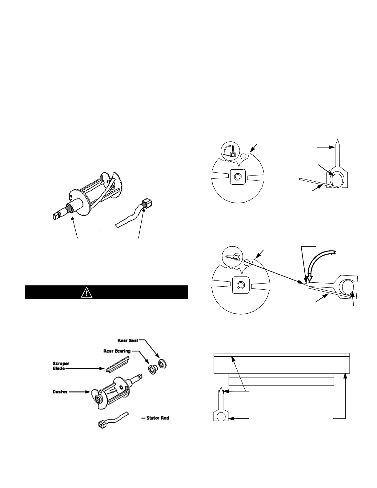
Fig. 12 Stator Rod and Dasher Lubrication....................................................................................................................5
Fig. 13 Dasher Assembly...............................................................................................................................................5
Fig. 14 Scraper Blade Installation and Wear Mark.........................................................................................................5
Fig. 15 Dasher Installation..............................................................................................................................................6
Fig. 16 Dasher Installation..............................................................................................................................................6
Fig. 17 Dasher (Front View)...........................................................................................................................................6
Fig. 18 Spigot Plunger Lubrication.................................................................................................................................6
Fig. 19 Front Plate Assembly.........................................................................................................................................7
Fig. 22 Carburetor Tube Assembly ................................................................................................................................7
Fig. 25 Drip Tray Assembly............................................................................................................................................7
Fig. 28 Consistency Control.........................................................................................................................................10
Fig. 30 Scraper Blade Wear Mark................................................................................................................................11
Fig. 31 Drip Chute........................................................................................................................................................11
Fig. 32 Clean Sharp Condenser Fins...........................................................................................................................11
Fig. 33 Torque Spring Adjustment Mechanism............................................................................................................12