SANJIANG JB-FSD-9082 User manual

Version:504600180308
1
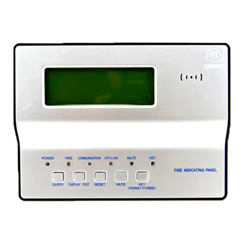
JB-FSD-9082 Fire Indicating Panel
------------Please read this operation manual carefully before installing and using the product.-----------
. IntroductionⅠ
JB-FSD-9082 Fire Indicating Panel(hereinafter referred to as Fire Indicating
Panel)is a microprocessor-controlled fire indicating panel, which is developed
and produced by Fanhai Sanjiang. The fire indicating panel is connected with
fire alarm control panel through RS485 bus line. Each floor can be installed with
a fire indicating panel , and when a detector or module triggers the alarm, the fire
indicating panel will emit a sound and light alarm, meanwhile the relevant fire
alarm information will be displayed on the screen.
. FeaturesⅡ
•Beautiful and elegant appearance
•Easy to operate, easy to install
•With a stable and reliable communication
of RS485 bus , and the maximum length of
the bus is over 1,000 meters
. Technical ParametersⅢ
•Voltage:DC 24V±20%
•Current:monitor state ≤32mA,alarm state ≤66mA
•Standard:GB 17429-2011《Fire Indicating Panel》
•Capacity:single fire indicating panel can display up to 99 pieces of
information
•Wiring system: five-wire system, power cord (+24V, GND), 485 bus (A,
B), PE line( ).
•Operating environment:
indoor;
temperature:-10℃~+50℃(14 ~122)℉℉;
relative humidity:≤95% RH (40℃,non-condensing);
•Dimensions:210.0mm×150.0mm×33.5mm
•Weight:0.5KG
. AppearanceⅣand Dimensions
The Figure 1 below illustrates overall dimensions of the panel.

2
Figure 1 Dimensions
. PⅤroduct Usage
1. Terminal description:
+24V:positive power input
GND:negative power input
A:signal terminal 485A
B:signal terminal 485B
:PE
2. Wiring diagram:
+24V
GND
A
B
SEC3002 JB-FSD-9082 JB-FSD-9082 JB-FSD-9082
Figure 2 Wiring Diagram

3
3. Function introduction and usage:
1)Indicators
Indicator Color Description
POWER green The power green indicator light is always
on when the power supply is normal.
FIRE red Lights when there is a fire alarm.
COMM. green
Normally for flashing state, long time
without blinking for communication fault.
FIRST
FIRE red Lights when the displayed message is the
first fire alarm.
MUTE green
Lights when the system or device is
muted.
2)Interface display
When the power is on, the interface shows
"System Normal" as shown in Figure 3. When the
fire display is in the normal monitor status, this
interface is displayed. The upper right corner of the
screen shows the current date and time, which is
synchronized with the controller's mainframe.
Fire indicating panel can
display up to 99 fire or feedback information,
the interface is as shown in Figure 4. When more
than one fire alarm or feedback message is
displayed, the next message will be scrolled, and
the time interval for rolling display is 8 seconds. If
the current displayed message is the first fire alarm,
the FIRST FIRE indicator will light.
3)Operating instructions
The fire indicating panel is set with five operation keys, which are
SELF-TEST key, MUTE key, left key, right key and ENTER key.
(1) Keyboard lock function
SELF-TEST key、set key、and ENTER key must be in the
state that the keyboard is unlocked, their operating function is
valid. When the display screen is off, press any key can wake it up,
then press the left key (set key) or SELF-TEST key, the interface
will prompt for the password. Press the left key + SELF-TEST +
right key + ENTER in turn to unlock the keyboard lock. After the
success of unlocking, it can operate the fire indicating panel
13-06-13
08:45:34
System
Normal.
Figure 3 normal
monitor state
01/99 06-13
08:15
Zone 01
OptDet
Figure 4 fire
display state

4
address, display mode, display language and self-check. After the
operation is completed, return to the normal operation interface,
press the ENTER key to close the keypad lock and turn off the
display.
(2)Self-test function
After the key is unlocked, press the SELF-TEST key, and the
fire indicating panel begins to self-check. At this time, the display
screen and indicators are all lit up for about 2 seconds, with the
honking of the horn . After the self-test, the keyboard lock will be
closed.
Note: When reporting fire alarm or in the setting interface,
can not carry out self-test !
(3) Mute function
Press the MUTE button can eliminate the fire alarm sound of the
machine, light up the mute indicator. The fire alarm control panel
is capable of remote silencing for the fire indicating panel. When
the fire alarm is received again, the fire display panel can re-fire
the fire alarm sound and extinguish the MUTE indicator light.
(4)Query function
After receiving two or more fire alarm messages, the machine
will automatically scroll to display the fire alarm information .
Every time you press the left key , it shows the last fire alarm
message, and each time press the right, it shows the next fire alarm.
If keys are not operated within 10 seconds, the machine will
automatically return to the first fire alarm message and begin the
scroll display.
(5)Return function
Press the ENTER key to exit the address setting interface,
while in other setting interfaces,right-click to exit the current
setting interface and return to the normal interface. If a fire alarm
occurs, the fire alarm interface shows, at this time users can not
enter or operate the setting interface until the system is reset.
4)Native settings
Enter the unlock state and then press the
set key to enter the setting interface, as shown
in Figure 5. Press the MUTE button to move
the cursor up, SELF-TEST key to move the
cursor down; Press the ENTER key to enter
address setup, language setup or display setup
these three corresponding menu of the cursor position. After
Address setup
Language setup
Display setup
Figure 5 native
settings

5
setting, press the ENTER button to save the Settings.
(1)address setup
After entering the address setting
interface, as shown in Figure 6, "01" indicates
the local address number. Press the left and
right key to move the cursor around, press the
MUTE key the number add one,while press
the SELF-TEST key it subtract one. After the setting is completed,
press the ENTER key to save and exit. If only query, also press
ENTER key to exit.
(2)language setup
After entering the language setting
interface, as shown in Figure 7, the Chinese
state is selected. Press the ENTER key to save
and exit after the setting is completed. If only
query, press the right key to exit.
(3)display setup
After entering the display setting
interface, as shown in Figure 8, the display is
open. Press the ENTER key to save and exit
after the setting is completed. If only query,
presstherightkeytoexit.
Note:The default address of the fire indicating panel is 01.
The default language is Chinese and the default display mode
is auto.
. Product Installation and DebuggingⅥ
1. Installation method
The installation of a fire indicating panel requires the use of a
special supporting base, with a method of a wall-mounted pre-buried 86
box. The external cable is directly connected to the fire indicating panel,
and for the convenience of wiring, it is suggested to draw the cable to a
10cm outside of the 86 box. The supporting base is shown in Figure 9,
the size of which is 132mm x 108mm x 6mm (length x width x height),
and the installation spacing of the base and 86 boxes is about 60mm.
2. Installation procedure
1) Fix the fire indicating panel base on the embedded 86 box.
2) Connect the cables led out of the box (86) according to the definition
of the terminal panel of the fire panel and fix it.
ADD:01
Figure 6 local
address setup
Chinese
English
Figure 7
language display
setup
OLED Open
OLED Auto
Figure 8 display
setup

6
3) Align the guide groove on the back of the fire indicating panel with the
guide rail of the base and press the panel downwards along the wall until
the guide groove on the back of the fire indicating panel fits the base fully.
Then tighten the hook on the back of the panel and the guide piece of the
fixed base with supporting screws (as shown in Figure 10).
Figure 9 foundation dimensions
in le tp ip e
pre-buriedbox
fire in d ica tin g p a n e l
fixed screw
Figure 10 fixation

7
3. Debugging method
1) After all the products are installed and confirmed, turn on the power of
the fire alarm control panel, set address number for the installed fire
indicating panel, and register the corresponding fire indicating panel on
the fire alarm controller. At the same time according to the physical
location of the fire indicating panel, configure the properties of the
panel, such as districts, blocks, floors, rooms and other information.
2)If the installation is correct and the data is configured correctly, the
COOM. Indicator will flash, indicating that the fire indicating panel has
been operating normally.
3)Simulate reporting multiple fire (or feedback) for test, the fire
indicating panel in the same or adjacent layers (according to "roll
layer" fire alarm controller Settings) with those simulated fire(or
feedback) will receive fire (or feedback) information, lit the fire
emergency lights, at the same time show the location and time of the
fire alarm. After the test, reset the fire alarm control panel, fire
indicating panel will be reset at the same time.
.ⅦFault Analysis and Troubleshooting
Faults Possible Reasons Solutions Remarks
The power is not normal Check the DC24V
power supply
Poor connection with the
controller cable
Check the
connection cable
The fire
indicating
panel shows
no display or
abnormal
display. LCD or the main CPU is
damaged
Return to factory
for maintenance
Indicating
panel
communicatio
n is abnormal.
The communication line
has something wrong, or
the host did not send the
inspection data.
Check if there is
any problem with
the signal line.
Unable to
report fire
alarm.
Check if the host has
properly registered fire
indicating panel.
The host registers
the indicating
panel.

8
Attention
1. Check whether there are any problems with the line before waking up the
machine, such as short circuit, open circuit, wrong connection, etc.
2. The fire indicating panel is a precision electronic product, which needs to
be managed by a special person.
3. Please do not wipe the machine surface with alcohol.
Address: 3/F., Guangcai Xintiandi Mansion, Nanshan Road, Nanshan District, Shenzhen,
Guangdong, 518054, China
Tel:+86(755)86226969 Fax:+86(755)86223939 Http://www.fhsjdz.com
Table of contents
Other SANJIANG Security System manuals