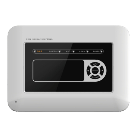
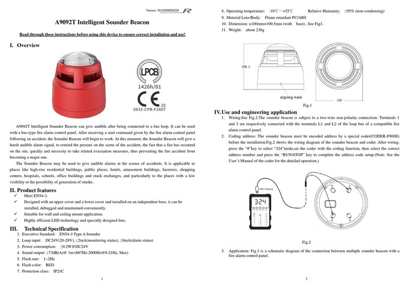
SANJIANG JB-FSD-982E User manual

Versionnumber:5025131129
Page1of
6
JB-FSD-982E
Fire
indicating
panel

Versionnumber:5025131129
Page1of
5
Instruction
Manual
of
JB-FSD-982
E
------PleasereadthisManualcarefullybeforeinstallingandusingtheproduct.-----
I.Productoverview
TheJB-FSD-982Efireindicatingpanel(indicatingpanelforshort)isakindofmicroprocessor-
controlledfireindicatingpaneldevelopedbyourcompany.Eachindicatingpanelisconnectedtoafire
alarmcontrolpanelproducedbyourcompanyviaaspecialRS-485interfacetoprocessanddisplaythe
datasentfromthefirealarmcontrolpanel.Eachfloorofabuildingmayhaveaindicatingpanelinstalled.
Whenthereisafirealarmonthefloorwheretheindicatingpanelisinstalled,ortheneighboringfloor
aboveorbelowit,theindicatingpanelwillgiveahorn/strobealarmanddisplaythefloorNo.,theroom
No.,andsomeotherpositioninformationofthefirealarm.
II.Productfeatures
üEachindicatingpanelisconnectedwithafirealarmcontrolpanelviaaRS-485bus.Atmost99
indicatingpanelsmaybeconnectedwitheachRS-485bus.
üTheindicatingpanelscandisplayfirealarmmessagesorfeedbackmessagesonlyratherthan
faultmessages,actionmessagesorothermessages.
üAfirealarmcontrolpanelmaybeusedforsettingthedisplayareaofaindicatingpanel.Theset
indicatingpanelcandisplaythefirealarmmessagesofthedesignatedarea(floordisplay)only.
Note:SeetheUser sManualofthefirealarmcontrolpanelforthesettingmethod.
üItcanreplaceaJB-FSD-981fireindicatingpanelina2100system.
III.Technicalparameters
1. Executivestandard:FireIndicatingPanel(GB17429-2011)
2. Displaycapacity:Eachindicatingpanelcandisplaythefirealarmmessagesoffloors-9~89and
atmost99firealarmmessagesorfeedbackmessages.
3. Wiringsystem:Four-wiresystem,powerlines(+24V,GND)andRS485signallines(485A,485B)
4. Operatingenvironment:Indoor;temperature:-10 ~+50 ;relativehumidity: ≤95%(40 ,
withoutcondensation)
5. Powersupply:DC24V ±20%
6. Overallpowerconsumption: <2W
IV.Appearanceanddimensions(seeFig.1)
Fig.1

Page2of
5
V.Useandengineeringapplication
1.Fig.2istheschematicdiagramoftheterminalsofaindicatingpanel.
Fig.2
Definitionsofterminals:
1--+24V(positiveinputterminal
ofthepowersupply)
2--GND(negativeinputterminal
ofthepowersupply)
3--OFF(reservedterminal)
4--COM(reservedterminal)
5--ON(reservedterminal)
6-- (earthterminalofthe
equipment)
7--485A(485businputterminal)
8--485B(485businputterminal)
2.Fig.3showsthegeneralfunctionsandwiringdiagramoftheproduct.
Fig.3
3.Functionsandusageoftheproduct:
1)Thedisplayedcontent
Fig.4NormalMonitoringStatus
Iftheindicatingpaneloperatesnormallyafterstartup, “Themachineisoperatingnormally,”as
showninFig.4willbedisplayed.Thecurrentdateandtimearedisplayedatthetoprightcornerofthe
screen.Thetimeissynchronouswiththatofthehostmachineofthefirealarmcontrolpanelandis
refreshedbyit(thereissomeintervalforrefreshing).Thecurrentlysupportedcontrolsystemisdisplayed
atthelowerrightcornerofthescreen.If “2100”isdisplayed,itmeansthata2100controlsystemis
supported;if9000isdisplayed,itmeansthata9000controlsystemissupported.Thespecificcontrol
systemsupporteddependsontheeighthdigitoftheaddressdialswitchonthebackoftheindicating
Addresscoding
window
Connecting
13-07-30
11:10:15
9000
Workingnormally

Page3of
5
panel.Formoredetails,see10)Setupofaddressparametersandcontrolsystem.
Theindicatingpanelcandisplay99firealarmmessagesorfeedbackmessages.Whensettothe
floordisplaymode,eachindicatingpanelcandisplayallthefirealarmsofthefloor.Whenthereare
multiplefirealarms,theequipmentwilldisplaytheminanautomaticrollingway.SeeFig.5forthe
interface.
Fig.5FireAlarmDisplayStatus
MCP meansthatthisfirealarmiscalledbyaManualcallpoint.
2)Displayandstatusesofindicators
Name Color Description
POWERGreen Ifthepowersupplyisnormal,thegreenPOWERindicatorwill
remainlit.
FIRERedItisoutatordinarytimesandwillbelitincaseofanyfirealarm(s).
COMMUNICATIONGreen Itblinksundernormalcircumstancesandisoutincaseofa
communicationfault.
OFFLINEYellowIfthepanelisnotonline,theyellowOFFLINEindicatorwillbelit.
MUTEGreenItwillbelitafterthesystemortheequipmentismuted.
KEYGreen Ifitislit,itsuggeststhatthekeyboardlockisunlockedandallkey
functionsareenabled;ifitisout,itsuggeststhatthekeyboardlock
islocked.
3)Functionsofthekeyboardlock
Keys SYSTEM TEST, QUERY,and RESET canbeoperatedonlywhenthekeyboardlockis
unlocked,otherwisetheycannot.Afteracombinedpasswordissetforthekeysandkeys KEY
(ENABLE/DISABLE), RESET and QUERYarepressedonceinorder,thekeyboardlockwillbe
unlockedandtheKEYindicatorwillbelit.Afterthe KEY (ENABLE/DISABLE) ispressedagainafterthat,
thekeyboardlockwillbelockedagainandtheKEYindicatorwillgoout.
4)Muting
Afterthe SYSTEM MUTEkeyispressed,thefirealarmtonewillbeeliminated,theMUTEindicator
willbelitandthenormallyclosedcontactoftherelaywillbeclosed.Afterreceivinganotherfirealarm,
anotherhorn/strobealarmsignalmaybetriggeredandtheMUTEindicatorwillgooutautomatically.
Note:AfterreceivingaMUTEcommandfromanautomaticfirealarmcontrolpanel,theindicating
panelcanalsorealizethemutingfunction.
5)Systemtest
Afterthe SYSTEM TESTkeyispressedafterthekeyboardlockisunblocked,alltheindicatorson
thedisplaypanelwillbelit,thebuzzerwillbuzzandtheLCDbacklightwillbelittoo.Twosecondslater,
alltheindicators(exceptforthePOWERindicator)willgoout,thebuzzerwillstopbuzzing,thesystem
testiscompletedandtheequipmentrestoresthestatusbeforethesystemtest.
Note:Thesystemtestfunctionisdisabledwhenthereisafirealarm.
6)Reset
Afterthe RESETkeyispressedafterthekeyboardlockisunblocked,alltheindicators(exceptfor
thePOWERindicator)onthedisplaypanelwillgoout,thefirealarmtonewilldisappear,thenormally
closedcontactoftherelaywillgetclosedandallthefirealarmrecordsoftheequipmentwillbedeleted.
Note:AfterreceivingaRESETcommandfromanautomaticfirealarmcontrolpanel,thedisplay
FIRETOTAL:01
01)13-07-3012:36
Z01-F01-R001SB MCP
0100001
13-07-30
11:10:15

Page4of
5
panelcanalsorealizetheresetfunction.
7)Query
Aftertheequipmentreceivestwoormorefirealarmmessages,itwilldisplaythefirealarm
messagesautomaticallyandcircularly.Afterthe QUERYkeyispressedafterthekeyboardlockis
unlocked,theequipmentwillenterthemanualdisplaystatus.Eachtimeafterthe QUERYkeyispressed,
theequipmentwilldisplaythenextfirealarmmessage.Ifthe QUERYkeyisnotoperatedwithineight
seconds,theequipmentwillautomaticallyreturntothecirculardisplaystatus.
8)Communicationindication
Whentheindicatingpaneliscommunicatingwiththeautomaticfirealarmcontrolpanelnormally,the
COMMUNICATIONindicatorontheindicatingpanelison,whichindicatorsnormalcommunication.
9)Setupofaddressparametersandcontrolsystem
Duringtheinstallationoftheindicatingpanel,itsaddressmustbesetaccordingtothespecific
installationlocation.TheaddressissetthroughaJP3dialswitchonthemainboardonthebackofthe
indicatingpanel(seeFig.2foritslocation).TheJP3dialswitchhaseightdialdigitsinall,whereinthefirst
totheseventhdigitsareusedforsettingtheaddress(seeFig.6andFig.7),andtheeighthdigitfor
choosingthe2100controlsystemorthe9000controlsystem.IftheeighthdialswitchispulledtotheON
position,the9000controlsystemwillbechosen(seeFig.6);ifitispulledtotheOFFposition,the2100
controlsystemwillbechosen(Fig.7).Correspondingcontentisdisplayedatthelowerrightcornerofthe
screen.
Fig.6AddressCodesofthe9000ControlSystemFig.7AddressCodesofthe2100ControlSystem
Iftheshort-circuitblockispulledtotheONposition,thedigitwillbesettobe “0”;ifitispulledtothe
OFFposition,thedigitwillbesettobe “1.”Addresssetupiscalculatedthroughabinarycodingmethod
(popularlyspeaking,binarynumberslike1,2,4,8,16,34,64andsoonareused).Forexample,ifthe
JP3dialswitchissettobe “1000000”(seeFig.6),theaddresswillbe1+0+0+0+0+0+0=1;andifitisset
tobe “0100100”(seeFig.7),theaddresswillbe0+2+0+0+16+0+0=18.
VI.Installationandwiring
Aspecialbaseisnecessaryduringtheinstallationofaindicatingpanel.AsshowninFig.8,the
externaldimensions,themountingholediameterandthemountingholespacingofthespecialbaseare
101.5mm×14mm×86mm(L×B×H),4.5mmand58mm~62mmrespectively.
Fig.8Fig.9
Embedded
box
F
astening
screw
indicating
panel
Inlet
pipe

Page5of
5
AJB-FSD-982Efireindicatingpanelconsistsofabaseandaindicatingpanel.Itissubjecttoa
wall-mountedinstallation.Itsexternalwiresmaybedirectlyconnectedwiththeterminalsontherear
paneloftheindicatingpanel.SeeFig.9fortheschematicdiagramofthemountingbaseoftheindicating
panel.
Basefixing:Fixthebaseoftheindicatingpanelontheembeddedbox.
Wiring:Connecttheleadsstretchingoutfromthejunctionboxwiththeterminalsontheindicating
panelanddoacorrectwiringaccordingtothecontentsmarkedontheterminals.
Fixtheindicatingpanel.
Arrangetheguideslotonthebackoftheindicatingpanelsoitalignswiththemountingbaseand
presstheindicatingpanelwithadownwardforcealongthewalluntiltheguideslotfitsthemountingbase
perfectly.Afterthat,lockthesmallhookontheupsideofthebackoftheindicatingpanelwiththeguiding
sheetonthemountingbasewithsomematchedscrews(seeFig.9).
Precautions
Pleaseinspectwhetherornotthecircuitoftheequipmentsuffersshortcircuit,opencircuit,wrong
wiringandotherdefects.
Theindicatingpanelisapreciseelectronicproductandthereforeneedstobemanagedbya
specificperson.Nootherpersonsareallowedtooperateitwithoutpermission.
Pleasewipethesurfaceoftheequipmentwithalcohol.
VII.Faultanalysisandtroubleshooting
Fault
phenomenon Possiblecause Troubleshootingmethod Remarks
Theindicatingpanel
failstoindicatingor
hasanabnormal
displayafterbeing
started.
a.Thepowersupplyisabnormal;
b.Theconnectionwiththefirealarm
controlpanelispoor;or
c.TheLCDortheCPUaredamaged.
a.InspecttheDC24Vpower
supply;
b.Inspectthepowerline;or
c.Sendtheindicatingpanel
backtothefactoryforrepair.
Theequipmentcannot
bestarted. TheDC24Vpowersupplyisnot
connected. InspecttheDC24Vpower
supply.
Thefirealarmcontrol
panelcannotbe
registered.
TheRS-485busispoorlyorwrongly
connected. InspecttheRS-485busand
reconnectit.
Theindicatingpanel
hasabnormal
communication.
Thesystemchosenisnotproperandthe
eighthdigitofthedialswitchiswrongly
pulled.
Pulltheeighthdigitofthedial
switchtothecorrectposition.
Table of contents
Other SANJIANG Security System manuals