manuals.online logo
Brands
  1. Home
  2. •
  3. Brands
  4. •
  5. SANJIANG
  6. •
  7. Security System
  8. •
  9. SANJIANG SG-991E User manual

SANJIANG SG-991E User manual

Version:2026100811E
1
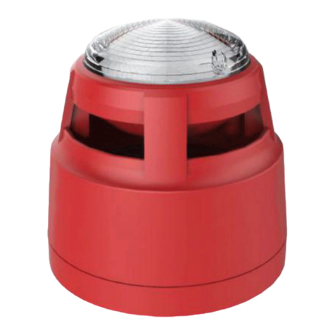
Instruction Manual ofSG-991E FireAlarm Horn/Strobe
------ Pleaseread thisManual carefullybeforeinstalling andusingtheproduct.-----
I. Product overview
TheSG-991Efire alarm horn/strobe (horn/strobefor short)isakindofproductmanufactured byourcompanytobeusedwith
bus-typefire alarmcontrolunits. Controlled by amicroprocessor,the horn/strobecanrealizereal-timecommunicationwitha
bus-typefire alarmcontrolunitandreceivethecontrolcommandssentbyit.Wheninarouting inspection,the red status
indicatorwill blink;afteranaccidenthappens, thehorn/strobewillstarttooperateafter
receiving astartupcommandfromthebus-typefirealarmcontrolunit.Theredstatus
indicatorwillremain litandthehorn/strobewill giveaflashingsignal andanaudible
alarm signal tonotifythepersons onthesceneof the accidentthatafire hasoccurred
onthesiteandofthenecessity totakerelatedevacuationmeasures, thuspreventing
thefire accidentfrombecomingamajor one.Thehorn/strobemaybe restoredtothe
monitoringstatusafterthe MUTEorRESET keyonthebus-type firealarm control unit
ispressed.
Thehorn/strobe maybeusedtogiveaudible alarmsandflashingalarmson the
scenesofaccidents. Itissuitable forplaceslikehigh-riseresidential buildings,public
places,hotels,amusementbuildings,factories,shopping centers,hospitals, schools,
officebuildingsand stock exchanges,particularlyplaceswithlowvisibility orthe
possibilityof generationof smoke.
II. Product features
üIt can realizecompleteelectroniccoding andin siturewritingwiththehelp of a
coder.
üTheaudible alarmand flashing alarmmaybesetfreely. Inotherwords, thehorn/strobe maygiveanaudiblealarm
and aflashing alarm atthesametimeorseparatelyandit canbeadaptedtodifferentworkingenvironments.
üDesigned withanuppercoverandalowercover,it can beinstalled, debuggedandmaintainedconveniently.
üItusesmultiple superbrightredLEDs aslightsources for visualdisplay,ensuringastriking display, alongerservice
lifeand lowpowerconsumption.
III.Technicalparameters
1. Executivestandard: GA385-2002
2. Operating voltage:DC24V(pulsemodulation)
3. Operatingcurrent:quiescent current: 1mA(thecurrentconsumedbythebus);alarmcurrent: 120mA@DC24V
4. Operatingenvironment: Temperature: 10 ~+55;relativehumidity: 95%(40,without condensation)
5. Flushingrate:one time/s
6. Alarmvolume: >85dB(measuredataplace3m in frontofthehorn/strobe)
7. Codingmethod:Electroniccoding
8. Wiringmethod:Four-wiresystem, non-polarity twosignalbuses(L1,L2)and powerlines(+24V, GND)
9. Matchedhost machine:JB-QBL-MN/300E
IV. Appearance and dimensions(seeFig.1)
Fig.1
V.Use andengineering application
1Fig.2istheschematic diagramoftherear cover ofthehorn/strobe.
2
Fig.2
2.Selectionbetweenaudiblealarmand flashingalarm:Select throughthejumper (JP1) belowthe
debugging port lidonthe backofthehorn/strobe, following theinstructionsofthe jumper.
Jumpersetup Function
Audiblealarmand flashing alarm(factory
default)
Flashing alarm(noaudiblealarms willbe
given)
Audiblealarm(noflashingalarmswillbe
given)
Warning:Theoutputmodeofahorn/strobecanbeoneofthethree optionsinthetable
above only.
3.Fig.3showsthegeneralfunctionsandwiring diagramoftheproduct.
Fig.3
4.Address coding:Whenahorn/strobeiscoded, itisunnecessarytodisassemblethe wireconnectingit
withthehostmachine;onlinecoding maybedone. Thespecific method isasfollows: Openthe cover
ofthe coding setup window,inserttheoutputplug (a four-pinconnector)ofthecoder intothe address
coding socket(the socketJ2inFig.2)ofthehorn/strobe,setthe coderwiththe coding function,
compilethecorrect address codeand presstheRUN keytocompletetheaddress coding.(Note: See
theUser’sManualofthecoder fordetailedoperationinformation.)
Warning:Itisnecessarytohave onlinecoding”donewhenthesystem ispoweredoff
orrelatedequipmentmay bedamaged.
Definitionsofterminals:
1---+24 powerinputterminal
2---GNDpower ground
3---Businput terminalL1
4---Businput terminalL2
Debuggingport
E
nlarged drawing
JP1:Setupofselectionbetween
audible alarm andflashingalarm
J2: Addresscodingsocket
Connectingterminal
3
5.Usage:Do notconnectthe powersupplyuntiltheaddressofthehorn/strobehasbeen setand
confirmed and thefire alarmcontrolpanelhasbeen properlyconnected.After thefirealarmcontrol
panelissuccessfullyreset,thered statusindicator(seeFig.3for its location) ofthehorn/strobe will
blink.After the horn/strobereceivesanoperationsignal,thestatusindicator willremainlitand the
horn/strobewill givebothhorn/strobealarmsignals.After thesystemis mutedor reset, thehorn/strobe
will stopoutputting horn/strobealarmsignalsand the statusindicator willstart toblinkagain.
VI.Installation and debugging
Aspecialbaseisnecessaryduring the installationofahorn/strobe.AsshowninFig.4,theexternal
dimensionsofthespecialbaseare142×84×10mm(L×B×H).Thehorn/strobeissubjecttoafour-wire
non-polarity connection:Terminals 1and 2are respectively connectedwiththeterminals +24Vand GND
oftheDC power supplyterminals3and 4arerespectively connectedwiththeterminalsL1 and L2 of the
signalbusofthe fire alarmcontrolpanel. SeeFig.5.
Fig.4Fig.5
Specificinstallationand debugging methods:
1. UsetwoM4screwstofixthematchedmountingbaseonthedesignated positionvia themountingholes
shownin Fig.4(the installationmay bedonehorizontallyorvertically. Chooseanytwoofthe sixmounting
holesforinstallation)asinstructedintheconstruction drawingandmakesurethematchedmountingbase
has been firmly installed.
2. Disconnectthepowersupplyofthefire alarmcontrolpanel and connectallthebases correctlyin theway
showninFig.5, whichis aconstructiondrawing.
Note: Whenthere arealotof horns/strobesinasystem, itis necessary toconsidertheloading capacity of
thepowersupplyofthe fire alarmcontrolpanel.AnexternalDC24Vauxiliarypower supplymightbe
necessary atthistime. Pleasefollowtheconstruction designdrawings.
3. Makesurethetypeofthe horn/strobematchesthetypegiven ontheconstructiondrawings.Useacoder to
code thehorn/strobeaccordingtothe addresscodemarked ontheconstructiondrawings.
4. After allthehorns/strobesareinstalled andchecked,connectthepowersupplyofthefire alarmcontrol
paneland conduct automaticlogin.
5. After ahorn/strobelogs intothe fire alarm control panel,thered status indicatorof the horn/strobewill blink;
afterthehorn/strobereceives an operationsignal,theredstatusindicatorwill remainlitandthehorn/strobe
willgivebothhorn/strobealarmsignals.Afterthesystemismutedorreset, thehorn/strobewillstop
outputtinghorn/strobe alarm signalsandthestatus indicatorwillrestoretothemonitoringstatus and startto
blinkagain.
VII. Precautions
1.Pay attentiontothe markingandpolarities oftheterminalsduring installationandwiring.
2.Donotmakedifferentproductssharethe sameaddress inasinglealarmcircuitorthesystemwillfailtooperate
normally.
3.Makesure duringinstallationthatthere are noobjectsin frontofthehorn/strobe thatblock the lightgiven bythe
horn/strobeand/orpreventthehorn/strobefromsounding.
4.Makethe installation complywithrelatedprovisionsoftheCodeforInstallation and AcceptanceofFire AlarmSystem
(GB50166-2007).
VIII. Maintenanceand inspection
1.As specifiedin nationalstandardCodeforInstallationandAcceptanceofFireAlarmSystem(GB50166-2007),atleast
quarterly testsshould bedonefor eachhorn/strobe.
2.Ifahorn/strobe failsdue toamaterial defectoramanufacturingprocess defect underthenormal conditionsofusein
oneyearfollowing thedateofitsdelivery,weshall repairorreplaceitfor free. However,thefaultsof thehorn/strobedue
toartificial damages,improper useorunauthorizedadjustment, reconstructionordisassemblyarenotcoveredinthe
guaranteeandweshallassumenoresponsibility for allthe consequencestherebycaused.
4
3.Wemayprovide apaidrepairservicefortheproductswithanyfaultsbeyondtheguaranteerange.Ifyouhavesuch
productsneedingrepair,pleasecontact us. When sendingsuchaproduct tousfor repair,youareexpectedtoprovide
someimportantinformationabouttheproduct,suchasthe phenomenon and possiblecauseof theproduct fault, sothat
wecanfind outthecauseofthefault in theshortest timeandtheinformationmay beused asareferenceinourfuture
product developmentandimprovement.
IX.Faultanalysisand troubleshooting
FaultphenomenonPossiblecause Troubleshooting method Remarks
The wiringis wrong. Inspect whetherornot thewiring
iscorrect.
The linkagefunctionhasnot
yetbeenenabled. Inspect whether ornotthe
generallinkage indicatorislit.
The short-circuitblockisset
wrong.
Inspect whether ornotthe
short-circuitblockis correctly set
andwhether or notitscontactis
good.
The horn/strobecannot
giveahorn/strobe alarm
signal.
The internalcircuitis
damaged. Send thehorn/strobeback tothe
factoryforrepair.

Other SANJIANG Security System manuals

SANJIANG A9092T User manual

SANJIANG

SANJIANG A9092T User manual

SANJIANG JB-FSD-982E User manual

SANJIANG

SANJIANG JB-FSD-982E User manual

SANJIANG A9091T User manual

SANJIANG

SANJIANG A9091T User manual

SANJIANG JB-FSD-9082 User manual

SANJIANG

SANJIANG JB-FSD-9082 User manual

SANJIANG SJ-LR08 User manual

SANJIANG

SANJIANG SJ-LR08 User manual

Popular Security System manuals by other brands

Concept Pro DEEP LEARNING PLUS user manual

Concept Pro

Concept Pro DEEP LEARNING PLUS user manual

Assa Abloy Yale SR-PIR manual

Assa Abloy

Assa Abloy Yale SR-PIR manual

Louwice P9 Quick setup guide

Louwice

Louwice P9 Quick setup guide

Pepperl+Fuchs LAL-SRW3 manual

Pepperl+Fuchs

Pepperl+Fuchs LAL-SRW3 manual

EVERSPRING SE812 user manual

EVERSPRING

EVERSPRING SE812 user manual

Aruba Networks FIPS 140-2 manual

Aruba Networks

Aruba Networks FIPS 140-2 manual

Climax HSGW Series user manual

Climax

Climax HSGW Series user manual

Fbt VAIE 4000 user manual

Fbt

Fbt VAIE 4000 user manual

AJAX StreetSiren user manual

AJAX

AJAX StreetSiren user manual

Velleman CCTVPROM9 Quick installation guide

Velleman

Velleman CCTVPROM9 Quick installation guide

Lascar EL-WiFi-Alert quick start guide

Lascar

Lascar EL-WiFi-Alert quick start guide

Duevi CE-LAN Technical manual

Duevi

Duevi CE-LAN Technical manual

MOOSE ZXSSD user guide

MOOSE

MOOSE ZXSSD user guide

Observint ECO4IR installation instructions

Observint

Observint ECO4IR installation instructions

bioscrypt V-Flex 4G installation guide

bioscrypt

bioscrypt V-Flex 4G installation guide

Pentair Flotec ALARM Series instruction manual

Pentair Flotec

Pentair Flotec ALARM Series instruction manual

Mace 80355 product manual

Mace

Mace 80355 product manual

Teltonika TBox20 user manual

Teltonika

Teltonika TBox20 user manual

manuals.online logo
manuals.online logoBrands
  • About & Mission
  • Contact us
  • Privacy Policy
  • Terms and Conditions

Copyright 2025 Manuals.Online. All Rights Reserved.