SankyoTateyama SankyoAlumi TF Series Programming manual

1
HZ1878-E
Precautions during installation
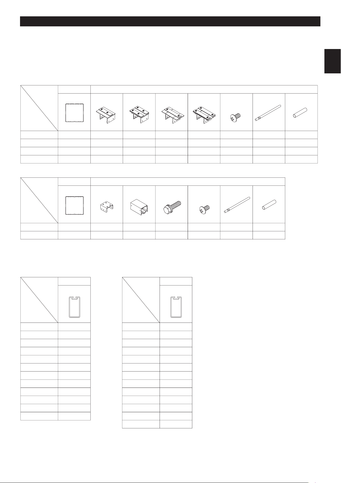
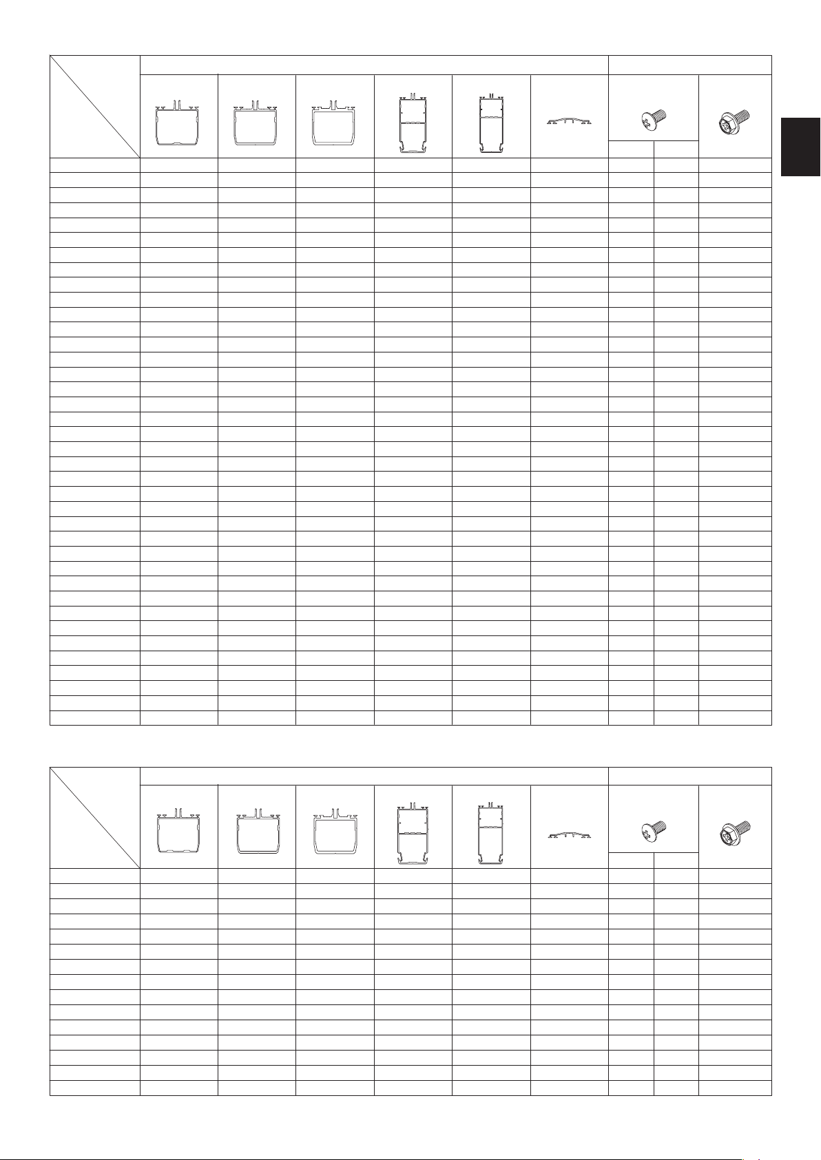
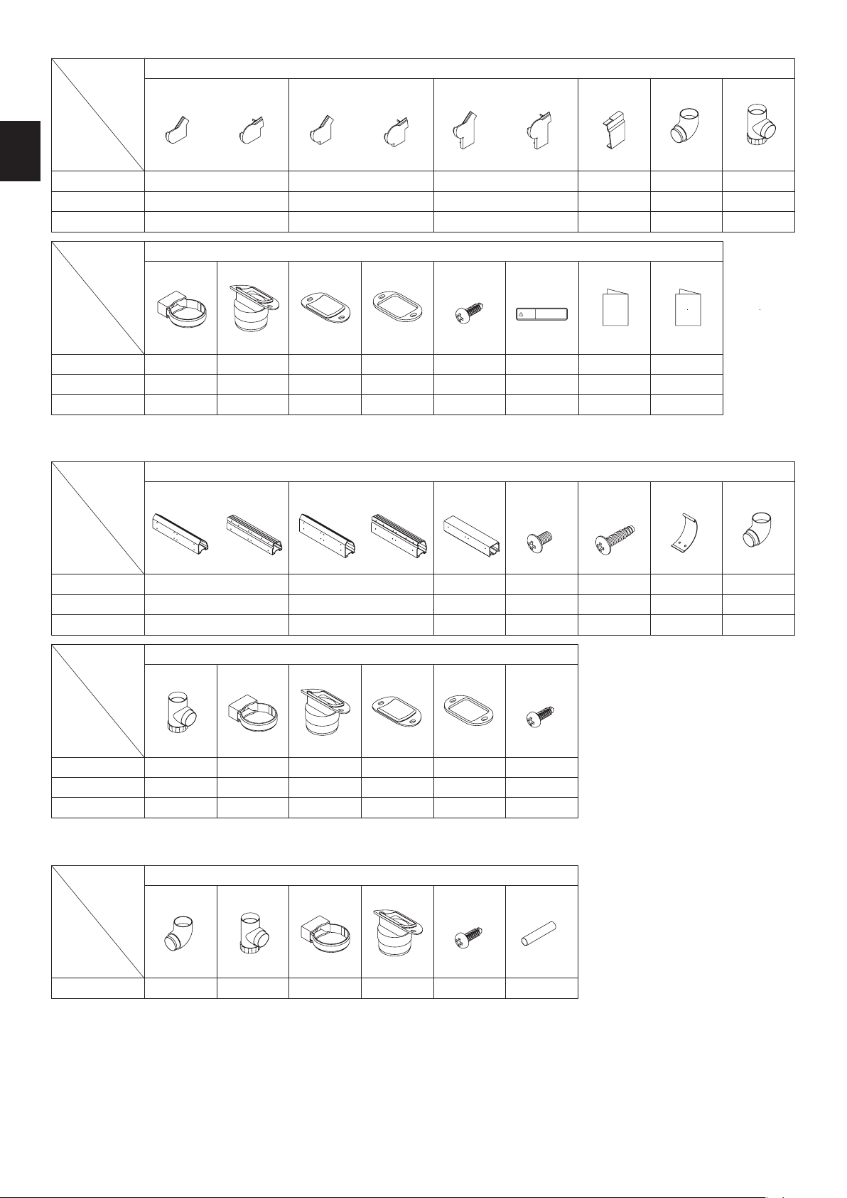
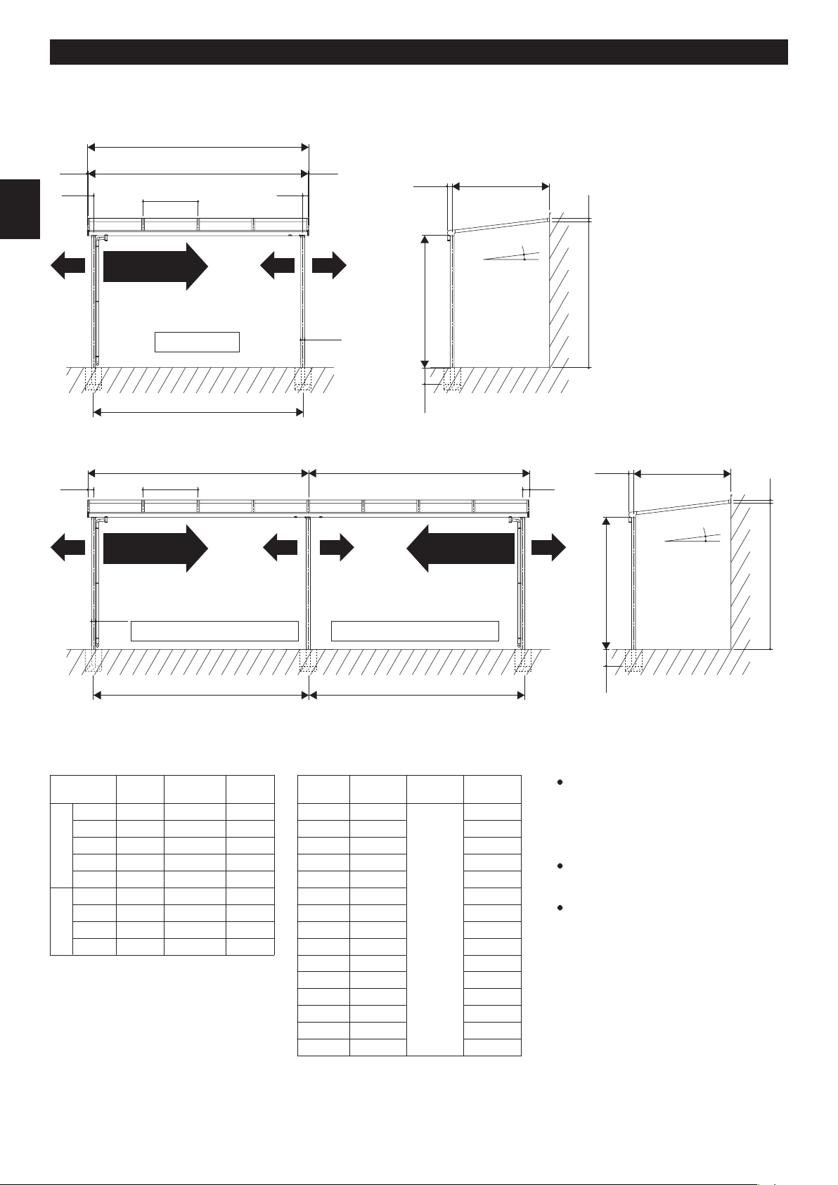
AssemblingmanualTerraceroofTR/TF-series600typeStandardinstallation
□Do not change or remodel it for another purpose except terrace roof.
□This product is for general areas. It has a snow accumulation strength of600N/m2(61.2kg/m2), which corresponds to 20cm of
fresh snowfall (specific weight 0.3). Do not install in heavy snow area.
□This product can be installed on the ground floor level. Please do not install on more than two -story.
□Do not install it in the place where snow slides down from the building roof directly or strong wind blow up this terrace roof.
□Standard installation of this product is installing on wooden body. When installing on the reinforced concrete structure or steel
structure except wooden house, please install by using optional parts and screws.
□Please check the house construction drawing and wall thickness before installation so that rear frame install firmly in the right
position of the house structural reinforcing materials (reinforced post, crossbeam, etc.). Do not install on the mortar part by
using plug anchors etc.
□Position the posts not to affect underground objects (water supply, drain pipes, etc.).
□When moving the posts, please follow the company specifications.
□Install it so that the exhaust of hot-water supply, heating and/or the car do not hit directly to the products and do not retain
around products. There is a possibility that the surface abnormality occurs as the coating film stripping.
Precautions during construction
□Follow the instructions and be sure that all the specified screws and bolts for assembly are tightened securely. Please tighten
the screws not to lean against the installation face.
□Tighten the M8 bolts at approx. 13Nm (130kgfcm) tightening torque.
□Do not use anything other than the specified parts or optional parts.
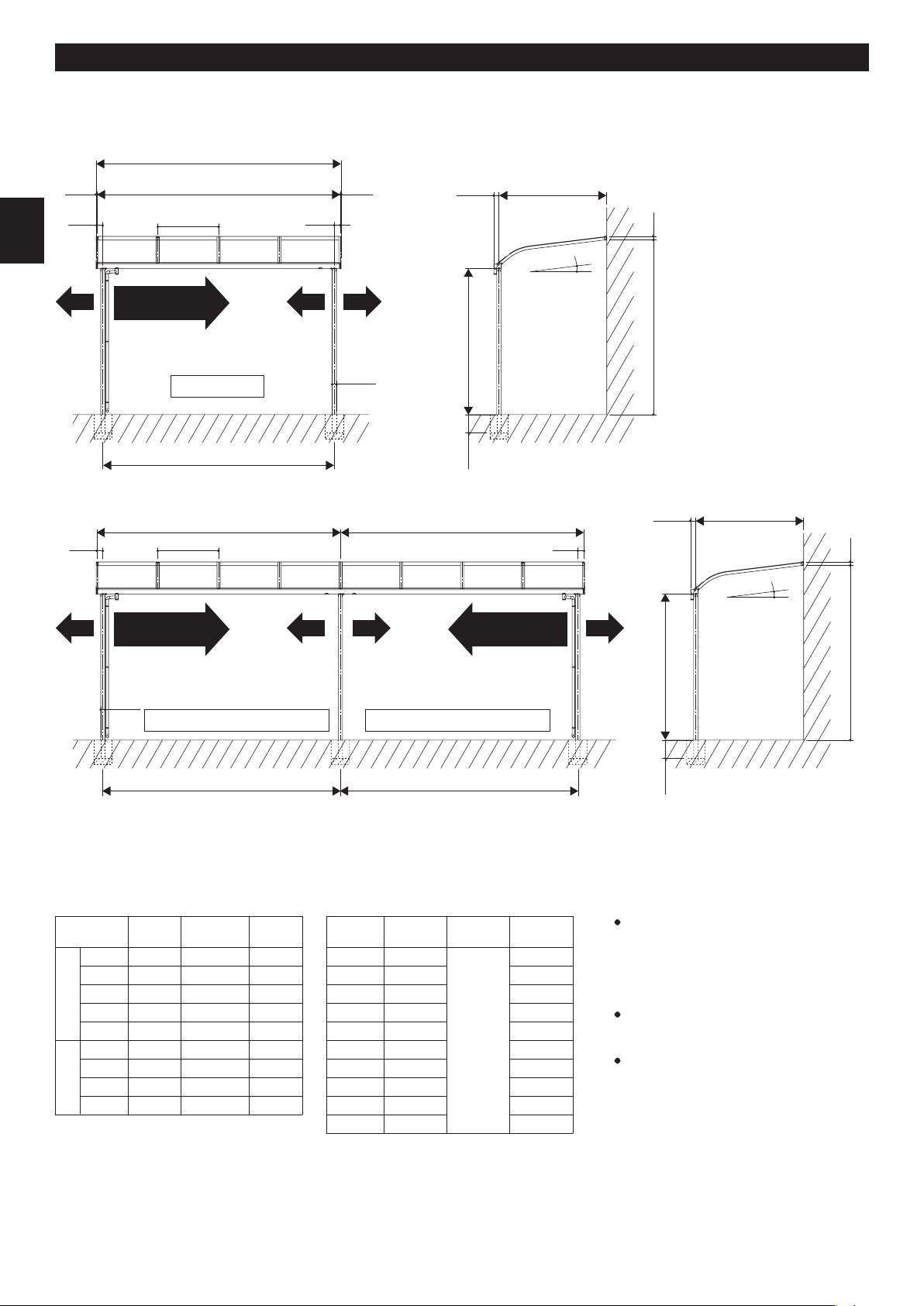
□The foundation should comply with or exceed dimension specifications.
□Please use the concrete and install the foundations.
□Allow sufficient curing time for the concrete (4 to 7 days) and do not place heavy objects on it or subject it to vibrations during
the curing period.
□Be sure to keep the note below to prevent aluminum materials corrode.
(1) Do not use sea sand for the foundation since it contains
salt and may cause corrosion. Do not use a cement
enhancer, water-reducing agent or cryoprotectant. They
may cause the posts to corrode.
(3) Be sure to provide gravel for the foundation to allow drain-
age, insert water drainage holes (φ5) at the base of the
posts and foundation. Failure to do so may lead to water
accumulation inside the posts and damage them if the
water freezes and expands inside.
(2) Immediately wipe off any mortar or stains from the surface
of aluminum parts since they may cause corrosion.
Thank you very much for choosing our company's products.
Please be sure to thoroughly read these instructions for assembly in order to properly and smoothly assemble or attach this pr oduct.
The precautions provided herein contain important information to ensure product performance, function, strength and safety.
Please be sure to follow them during construction.
Construction shall be implemented by professionals. Problems may occur if the product is installed by someone without the
proper knowledge.
Please be sure to return this manual to the owner after construction.
Notice
sea
sand
cement
enhancer water-
reducingcryopro
tectant
water
drainage
hole

Necessary tools and materials for installation
2
□Be sure to put the sealant glue as the following.
□After construction, check the products to see if the bolts, screws, nuts, etc. loosen or any dangerous places exist.
□Be sure to check if the product has scratches, dents or dint.
□Be sure to explain product operation procedures, maintenance and inspection methods to the owner.
□Electric drill, Drill, Tapping drill (M5)
□Ratchet wrench, Adjustable end wrench
□Electric screwdriver
□Measure, Level, Plumb bob, Cutter, Pillar, Plastic hammer
□Cropper or Saw
□Foundation materials(Cement, Aggregate,etc)
□Sealant, Caulk gun, Pallet, Back-up materials, Glue
Please prepare tools and materials as needed.
INDEX
●Precautions during installation
●Precautions during construction
●Necessary tools and materials for installation
●INDEX
●Packaging detail
●Drawings and dimension table
Drawings / Sealing parts
Embedding post
1. Rear frame installation
2. Post and front frame installation
3. Temporal fixing of post and front frame
4. Side frame and rafter installation
5. Furring strips installation
1
1〜2
2
2
3〜7
8〜11
12
13
14
15
16
16
17
Installation procedure
1. Single unit installation procedure
6. Roof panel installation
7. Roof retainer installation
8. Attaching caps
9. Attaching rain gutter parts
10. Attaching labels
1. Rear frame installation
2-①. Front frame processing
2-②. Post and front frame assembling
3-②. Connecting post and front frame
4-②. Rafter (connecting part) installation
9-②. Attaching rain gutter parts
17
18
19
20
20
21
21
22
23〜25
25
25
Drawings 26〜28
14〜20
12〜25
2. Installation procedure of connecting unit 21〜25
rust dust
oil
water
sealing
sealing
(1) Wipe off any stains from
the sealing part.
(2) Be sure to apply a
sealant, as specified.
(3) After putting the sealant
glue on the hole made in
its all wall body, fully
tighten the screw.
(4) Seal completely deep
enough and finish the
surface with a pallet.
■ marks indicate making holes on-site. Please make holes referring the manual.
■ marks indicate doing sealing work. Please do sealing work referring the manual.

3
Packaging detail
Packaging detail
□Please open the captioned carton and check all contents in advance.
□Please check the parts defective or damage.
□After opening the carton box, please stock not to deface the products.
□We packed some extra screws in the parts box. (X) number is necessary quantity for installation.
Materials Parts
■Post set
(Depth type 30 to 15) ●part (N: Standard post, L: Long post)
TRH●-2
TRH●B-2
TRH●-1
TRH●B-1
2
2
1
1
2
2
1
1
1
1
1
1
post
2
post fixing part A
(end)
GB8631
2
post fixing part B
(end)
GB8633
1
post fixing part A
(middle)
GB8632
1
9(8)
9(8)
5(4)
7(6)
post fixing part B
(middle)
GB8634
round gutter
GA4923GA0073
Shape name
Parts ID
Materials Parts
Shape name
Parts ID
Materials
Shape name
Parts ID
Materials
Shape name
Parts ID
■Furring strip set
○part (E: rafter pitch 909mm type, M: rafter pitch 1000mm type)
(Depth type 30 to 80)
TRN-○-1
TRN-○-2
TRN-○-3
TRN-○-4
TRN-○-5
TRN-○-6
TRN-○-8
TRN-○-9
TRN-○-10
TRN-○-12
TRN-○-15
TRN-E-18
1
2
3
4
5
6
8
9
10
12
15
18
furring strip
(Depth type 90 to 2A)
TRN-○H-2
TRN-○H-4
TRN-○H-6
TRN-○H-8
TRN-○H-10
TRN-○H-12
TRN-○H-16
TRN-○H-18
TRN-○H-20
TRN-○H-24
TRN-○H-30
TRN-EH-36
TRN-EH-40
2
4
6
8
10
12
16
18
20
24
30
36
40
furring strip
(Depth type 18 to 2A)
TRHNC-2
TRHNC-1
2
1
2
1
8
4
13(12)
7(6)
2
post
front frame support part
(for 18, 2A)
hexagon bolt
(sems)
small truss screw
5×10×10
small truss screw
5×10×10
anchor rod
GB8638 M8×40
2
1
anchor rod
GA0073
1
1
round gutter
GA4923
post connecting part
(for 18, 2A)
GB8637

4
Packaging detail
Materials Parts
■Width set
(Depth type 30 to 80)
T□MN-60A、-200A
T□MN-60B、-200B
T□MN-60C、-200C
T□MN-90A、-300A
T□MN-90B、-300B
T□MN-90C、-300C
T□MN-12A、-400A
T□MN-12B、-400B
T□MN-12C、-400C
T□MN-15C、-500C
T□MN-15D、-500D
T□MN-18D
1
1
1
standard front frame A
coach screw (sems)
6×90
1
1
1
standard front frame B
1
1
1
1
standard front frame C
1
1
standard front frame D
1
1
1
1
1
1
1
1
1
1
1
1
3
3
3
4
4
4
5
5
5
6
6
7
rear frame A
R type F type R type F type R type F type R type F type
R type F type
ES0445
□part (R: R type, F: F type)
Materials Parts
■Side frame set
T□SN-30
T□SN-40
T□SN-50
T□SN-60
T□SN-70
T□SN-80
T□SN-90
T□SN-10
T□SN-11
T□SN-12
TFSN-13
TFSN-14
TFSN-15
TFSN-18
TFSN-2A
Y■SN-30
Y■SN-40
Y■SN-50
Y■SN-60
Y■SN-70
Y■SN-80
Y■SN-90
Y■SN-10
Y■SN-11
Y■SN-12
YSSN-13
YSSN-14
YSSN-15
YSSN-18
YSSN-2A
right left each 1pc
right left each 1pc
right left each 1pc
right left each 1pc
right left each 1pc
right left each 1pc
right left each 1pc
right left each 1pc
18(16)
20(18)
24(22)
26(24)
42(40)
46(44)
32(30)
34(32)
38(36)
40(38)
15(14)
18(16)
22(20)
24(22)
40(38)
44(42)
32(30)
34(32)
34(32)
36(34)
38(36)
40(38)
42(40)
61(58)
65(62)
side frame A upset bolt
M5x12
right left each 1pc
right left each 1pc
right left each 1pc
right left each 1pc
right left each 1pc
side frame B
right left each 1pc
right left each 1pc
side frame C roof retainer (end)
2
2
2
2
2
2
2
2
2
2
2
2
2
2
2
2
2
2
2
2
2
2
2
2
2
2
2
2
2
2
small truss screw
5×10×10
①②
①② ①② ①②
R type F type R type F type ES0446
□part (R: R type, F: F type)、■part (R: R type, S: F type)
Materials Parts
(Depth type 90 to 12)
T□MN-60DH、-200DH
T□MN-90DH、-300DH
T□MN-12DH、-400DH
T□MN-15DH、-500DH
T□MN-18DH
1
1
1
1
1
standard front frame D
coach screw (sems)
6×90
1
1
1
1
1
5
7
9
11
13
rear frame B
ES0445
Materials Parts
(Depth type 13 to 2A)
TFMN-60EH、-200EH
TFMN-90EH、-300EH
TFMN-12EH、-400EH
TFMN-15EH、-500EH
TFMN-18EH
1
1
1
1
1
F standard front frame
coach screw (sems)
6×90
1
1
1
1
1
5
7
9
11
13
rear frame B
ES0445
Shape name
Parts ID
Shape name
Parts ID
Shape name
Parts ID
Shape name
Parts ID
right left
each 1pc
right left
each 1pc
right left
each 1pc
right left
each 1pc
right left
each 1pc
right left
each 1pc
right left
each 1pc
right left
each 1pc
right left
each 1pc
right left
each 1pc

5
Packaging detail
Parts
■Connecting rafter set □part (R: R type, F: F type)
T□TN-30W
T□TN-40W
T□TN-50W
T□TN-60W
T□TN-70W
T□TN-80W
T□TN-90W
T□TN-10W
T□TN-11W
T□TN-12W
TFTN-13W
TFTN-14W
TFTN-15W
TFTN-18W
TFTN-2AW
1
1
1
1
12(11)
13(12)
16(15)
18(16)
27(25)
29(27)
21(19)
22(20)
25(23)
26(24)
11(10)
12(11)
15(14)
16(15)
26(24)
28(26)
21(19)
22(20)
23(21)
24(22)
25(23)
26(24)
27(25)
38(36)
40(38)
4
4
2
2
2
2
2
2
2
2
2
2
2
2
2
1
1
1
1
1
1
1
1
1
1
1
1
1
1
1
connecting rafter A
1
1
1
connecting rafter B
1
connecting rafter C
1
1
1
1
1
connecting rafter D
1
1
connecting rafter E
upset bolt
M5×12
ES0446
small truss screw
5×10×10
roof retainer
R type F type
■Rafter set □part (R: R type, F: F type)
T□TN-30-3
T□TN-30-2
T□TN-30-1
T□TN-40-3
T□TN-40-2
T□TN-40-1
T□TN-50-3
T□TN-50-2
T□TN-50-1
T□TN-60-3
T□TN-60-2
T□TN-60-1
T□TN-70-3
T□TN-70-2
T□TN-70-1
T□TN-80-3
T□TN-80-2
T□TN-80-1
T□TN-90-5
T□TN-90-4
T□TN-90-3
T□TN-10-5
T□TN-10-4
T□TN-10-3
T□TN-11-3
T□TN-11-2
T□TN-12-3
T□TN-12-2
TFTN-13-3
TFTN-13-2
TFTN-14-3
TFTN-14-2
TFTN-15-3
TFTN-15-2
TFTN-18-3
TFTN-18-2
TFTN-2A-3
TFTN-2A-2
3
2
1
3
2
1
3
2
1
3
2
1
29(27)
20(18)
10(9)
32(30)
22(20)
11(10)
41(39)
28(26)
14(13)
44(42)
30(28)
15(14)
72(69)
48(46)
25(23)
79(75)
53(50)
27(25)
89(85)
71(68)
54(51)
95(90)
76(72)
57(54)
66(63)
44(42)
69(66)
46(44)
26(24)
18(16)
9(8)
29(27)
20(18)
10(9)
38(36)
26(24)
13(12)
41
(39)
28(26)
14(13)
69(66)
46(44)
24(22)
76(72)
50(48)
26(24)
89(85)
71(68)
54(51)
95(90)
76(72)
57(54)
60(57)
40(38)
63(60)
42(40)
66(63)
44(42)
69(66)
46(44)
72(69)
48(46)
107(102)
71(68)
113(108)
76(72)
3
2
1
3
2
1
3
2
1
3
2
1
3
2
1
3
2
1
5
4
3
5
4
3
3
2
3
2
3
2
3
2
3
2
3
2
3
2
3
2
1
3
2
1
3
2
1
3
2
1
3
2
1
3
2
1
5
4
3
5
4
3
3
2
3
2
3
2
3
2
3
2
3
2
3
2
rafter A
3
2
1
5
4
3
5
4
3
rafter B
3
2
1
rafter C
3
2
3
2
3
2
3
2
3
2
rafter D
3
2
3
2
rafter E upset bolt
M5×12
ES0446
small truss screw
5×10×10
roof retainer
R type F type
Materials Parts
Shape name
Parts ID
Materials
Shape name
Parts ID

6
Packaging detail
Parts
■Parts box □part (R: R type, F: F type)、◇part (D: R type, DE: F type)
T□BN-ABS
T□BN-CS
T□BN-◇S
right left
each 1pc
right left
each 1pc
right left
each 1pc
1
1
1
R front frame cap
A
GB8640
F front frame cap
A
GB8643
R front frame cap
B
GB8641
F front frame cap
B
GB8644
R front frame cap
C
GB8642
F front frame cap
C
GB8645
right left each 1pc
right left each 1pc
right left each 1pc
drain elbow
GA6461
2
2
2
elbow
GA4932GB8653
rear frame cap
Parts
T□BN-ABS
T□BN-CS
T□BN-◇S
1
1
1
3
3
3
1
1
1
1
1
1
saddle
GB8077
8(7)
8(7)
8(7)
assembling manual
HZ1878
1
1
1
drain gutter
GA6456
1
1
1
gutter cap
GA6455
1
1
1
gasket
GS1651
instruction manual
GD-W40BGL-PCI
caution label
20cm
ES0063
drilling screw
4×13×8
Parts
■Parts box (for connecting)
■Rain gutter parts set
□part (R: R type, F: F type)、◇part (D: R type, DE: F type)
T□BN-ABW
T□BN-CW
T□BN-◇W
9(8)
9(8)
5(4)
2
2
2
R front frame
sleeve
GB8655
F front frame
sleeve
GB8657
R front frame sleeve
(for front frame C)
GB8656
F front frame sleeve
(for front frame D)
GB8658
front frame connecting
sleeve (W)
GB8662
small truss screw
5×10×10
1
1
1
1
9(8)
9(8)
9(8)
elbow
GA4932
elbow
GA4932
1
1
1
front frame cover
GA9337
tapping truss screw
5×20×10
Parts
T□BN-ABW
T□BN-CW
T□BN-◇W
1
1
1
drain elbow
GA6461
10(9)
10(9)
10(9)
1
1
1
gasket
GS1651
3
3
3
saddle
GB8077
1
1
1
drain gutter
GA6456
1
1
1
gutter cap
GA6455 ES0063
drilling screw
4×13×8
Parts
TRTAD 2
drain elbow
GA6461
16(5)1
saddle
GB8077
3
drain gutter
GA6456
1
ES0063
drilling screw
4×13×8
Shape name
Parts ID
Shape name
Parts ID
Shape name
Parts ID
Shape name
Parts ID
Shape name
Parts ID
積雪が20cmを超える前に
雪下ろしをしてください。
注意
round gutter
GA4923

7
Packaging detail
Quantity
■Roof panel set
□part (R: R type, F: F type)
◆part (P: polycarbonate, S:polycarbonate mat SI, CM: Heat protection polycarbonate mat SI, B: Stain proofing polycarbonate clear)
○part (E: rafter pitch 909mm, M: rafter pitch 1000mm)
T□P◆-○30-2
T□P◆-○30-3
T□P◆-○30-4
T□P◆-○40-2
T□P◆-○40-3
T□P◆-○40-4
T□P◆-○50-2
T□P◆-○50-3
T□P◆-○50-4
T□P◆-○60-2
T□P◆-○60-3
T□P◆-○60-4
T□P◆-○70-2
T□P◆-○70-3
T□P◆-○70-4
T□P◆-○80-2
T□P◆-○80-3
T□P◆-○80-4
2
3
4
2
3
4
2
3
4
2
3
4
2
3
4
2
3
4
Quantity
T□P◆-○90-4
T□P◆-○90-6
T□P◆-○10-4
T□P◆-○10-6
T□P◆-○11-2
T□P◆-○11-3
T□P◆-○12-2
T□P◆-○12-3
TFP◆-○13-2
TFP◆-○13-3
TFP◆-○14-2
TFP◆-○14-3
TFP◆-○15-2
TFP◆-○15-3
TFP◆-E18-2
TFP◆-E18-3
TFP◆-E2A-2
TFP◆-E2A-3
4
6
4
6
2
3
2
3
2
3
2
3
2
3
2
3
2
3
10
■Non-wooden house parts box
(Aeration construction method (siding panel installation))
( RC structure )(Light-gauge steel structure )
BTB-B11
Anchor bolt
M6×60
10 10
BTB-B12
HEX screw
6×70
washer
ES0325ES0445
50
■Hexagon bolts set
BTB-V14
hexagon bolt (sems)
M5×12
ES0326
10
BTB-B23
coach screw
(sems)
6×120
3
Parts
BTB-B13
spacer
(L=300)
GS1040
Shape name
Parts ID
Parts
Shape name
Parts ID
Parts
Shape name
Parts ID
Parts
Shape name
Parts ID
Parts
Shape name
Parts ID

8
Drawings・Dimension table
500 6060
100 100 6060
Drawings・Dimension table
When installing the side panel, move the post 60mm toward the side frame from the standard post position (L).
【R type】
Side frame center
W、W1、W2
Nominal width
909 type 1000 type
60
90
12
15
18
1618
2527
3436
4345
5254
1818
2727
3636
4545
5454
200
300
400
500
1800
2800
3800
4800
2000
3000
4000
5000
Roof width
WY
1845
2754
3663
4572
5481
2027
3027
4027
5027
Post center
L
■Width dimension
H
Nominal depth
30
40
50
60
870
1170
1470
1770 2400
standard post
long post
3400
70
80
90
10
11
12
2070
2370
2670
2970
3270
3570
()
h※
2759.1
2796.0
2832.8
2869.6
2906.5
2943.3
2980.1
3017.0
3053.8
3090.6
D
■Depth dimension・Height
※
In case of connecting installation
L1=W1−100
L2=W2−100
・h dimension formula (in case of
front frame (S))
h=H+D×tan7°+252.3
(tan7°≒0.123)
・In case of long post, add 1000mm
to h dimension.
・h dimension differs depending on
the front frame size, add the
additional value to h dimension
referring “h dimension additional
value” in the table on next page.
L
□70
100100
W 13.513.5
P
WY
standard post:2400
long post:3400
300
D
59
※h=H+D×t an7°+252.3
【In case of front frame (S)】
7°
0〜73、383〜500
rain gutter installation side
0〜73、383〜500
rain gutter installation side
G.L
G.L
(sideframecenter)
(rear frame attachment
face to post center)
(Postcenter)
L1
(Postcenter)
L2
(Postcenter)
(roofwidth)
□70
W1 W2
P100 100
standard post:2400
long post:3400
300
D
59
※h=H+D×t an7°+252.3
7°
0〜73、383〜500
rain gutter installation side
(rear frame attachment
face to post center)
【In case of front frame (S)】
(85.5)
(85.5)
Single unit
Connecting installation Connecting installation

9
Drawings・Dimension table
Nominal width
Nominal depth
D
W
rear frame
rafter
side frame
rafter pitch P
number of furring strip per panel
60
200
90
300
12
400
15
500
18
30
870
40
1170
50
1470
60
1770
A
A
Front frame A
(h dimension additional value 0)
Front frame C
(h dimension additional value : 20)
Front frame D
(h dimension additional value : 70)
Front frame B
(
h dimension additional
value 0)
12323
B
AB
BDC
B
909(1000) 454.5(500)
70
2070
80
2370
90
2670
10
2970
11
3270
12
3570
1818
2000
2727
3000
3636
4000
4545
5000
5454
■Material instruction guide table
A
for connecting
BCD
■Rafter
50
45
50
45
50
45
50
95
35
95
50
45
AB
■Side frame
35
45
Front frame (S) Front frame (M) Front frame (L)
AB
CD
■Front frame
71.2
70
71
(74.6)
71
(74.6)
71
(74.6)
20 (74.6)
AB
■Rear frame
(37.5)
59
(37.5)
59

10
Drawings・Dimension table
50060 60
() ()
() ()
Depth
type 18
and 2A is
20mm.
Depth
type 18
and 2A is
20mm.
Depth
type 18
and 2A is
20mm.
Depth
type 18
and 2A is
20mm.
Side frame center
W、W1、W2
Nominal width
60
90
12
15
18
1618
2527
3436
4345
5254
1818
2727
3636
4545
5454
200
300
400
500
1800
2800
3800
4800
2000
3000
4000
5000
Roof width
WY
1845
2754
3663
4572
5481
2027
3027
4027
5027
Post center
L
■Width dimension
H
Nominal depth
30
40
50
60
870
1170
1470
1770
2400
standard post
long post
3400
70
80
90
10
11
12
13
14
15
18
2A
2070
2370
2670
2970
3270
3570
3870
4170
4470
5370
5970
()
h※
2543.9
2580.8
2617.6
2654.4
2691.3
2728.1
2764.9
2801.8
2838.6
2875.4
2912.3
2949.1
2985.9
3096.5
3170.1
D
■Depth dimension・Height
Drawings・Dimension table
When installing the side panel, move the post 60mm toward the side frame from the standard post position (L).
【F type】
909 type 1000 type
※・h dimension formula (in case of
front frame (S))
h=H+D×tan7°+37.1
(tan7°≒0.123)
・In case of long post, add 1000mm
to h dimension.
・h dimension differs depending on
the front frame size, add the
additional value to h dimension
referring “h dimension additional
value” in the table on next page.
□70
7°
300
D
59
※h=H+D×tan7°+37.1
7°
300
D
59
※h=H+D×tan7°+37.1
【In case of front frame (S)】
L
100
W13.5 13.5
P
WY
G.L
G.L
L1 L2
□70
W1 W2
P100 100
100 100 6060
100 (85.5)
(85.5)
0〜73、383〜500
rain gutter installation side
standard post:2400
long post:3400
0〜73、383〜500
rain gutter installation side
(sideframecenter)
(rear frame attachment
face to post center)
(Postcenter)
(Postcenter) (Postcenter)
(roofwidth)
standard post:2400
long post:3400
0〜73、383〜500
rain gutter installation side
In case of connecting installation
L1=W1−100
L2=W2−100
Single unit
Connecting installation Connecting installation

11
Drawings・Dimension table
rear frame
rafter
side frame
rafter pitch P
number of furring strip per panel
60
200
90
300
12
400
15
500
18
30
870
40
1170
50
1470
60
1770
A
A
Front frame A
(h dimension additional value 0)
Front frame C
(
h dimension additional value : 20
)
for connecting
Front frame D
(h dimension additional
value : 70)
Front frame E
(h dimension additional value : 70)
Front frame B
(
h dimension additional
value 0)
12 32 53
B
AB
C
BDEC
B
909(1000) 454.5(500)
70
2070
80
2370
90
2670
10
2970
11
3270
12
3570
13
3870
14
4170
15
4470
18
5370
2A
5970
1818
2000
2727
3000
3636
4000
4545
5000
5454
■Material instruction guide table
Type 18 and 2A is
rafer pitch 909mm only.
ABCDE
■Rafter
50
45
50
45
50
45
50
95
50
120
35
95
35
120
50
45
35
45
ABC
■Side frame
Front frame (S) Front frame (M) Front frame (L)
ABCDE
■Front frame
71.2
70
71
(74.6)
71
(74.6)
71
(74.6)
71.2
70(74.6)
20 (74.6)
AB
■Rear frame
(37.5)
59
(37.5)
59
Nominal width
Nominal depth
D
W

12
Installation procedure
front frame
front frame
Seal around
drain hole.
Seal to screw holes. Seal to screw holes.
■A view (
drain hole part
)■B view (
drain hole cap part
)
front frame cap
φ4.5〜φ5
rear frame
whole length sealing
rear frame connecting part
rear frame cap
front frame
front frame connecting sleeve
front frame cover
front frame
connecting sleeve
front frame cover
A
B
front frame cap
front frame
rear frame
sealing
rear frame cap
After making
holes, do
sealing work
into the holes.
rear frame
furring strip
side frame
rear frame
roof retainer
(end)
front frame cap
post fixing part
anchor rod
rafter
roof panel
post fixing part
(middle)
front frame cover
front frame
post
rear frame cap
roof retainer
side frame
elbow(85°)
drain gutter
gasket
round gutter
drain elbow
gutter cap
front frame
Configuration diagram・sealing point
This manual shows typical examples of R-type. F-type is same procedure, but the different points are indicated.
Rear frame Rear frame caps
front frame cap
front frame connecting part
rain gutter parts
P.20
P.23
P.19
P.19
P.14、P.21
front frame cap
Installation procedure

13
Drawings・Dimension table
() ()
()()
Depth type 18
and 2A is 20mm.
Depth type 18
and 2A is 20mm.
Depth type 18
and 2A is 20mm.
Depth type 18
and 2A is 20mm.
When installing the side panel, move the post 60mm toward the side frame from the standard post position (L).
indicates post movable range dimension.
100 L 100
W
Rear frame
D
A A
A
A
100 L 100
W
L1 L2
W1 W2
Rear frame Rear frame
B
B
D
A A
A
A
■Depth of basement
300
■Depth of basement
300
Depth
Width
909 type
1000 type
Nominal depth
30
40
50
60
70
80
90
10
60
1618
90
2527
12
3436
15
4345
18
5254
200 300 400 500
1800 2800
□300
□400 □500
□400
3800 4800
870
1170
1470
1770
2070
2370
2670
2970
Nominal width
L(mm)
Nominal width
L(mm)
D(mm)
■Base dimension A
Depth
Width
909 type
1000 type
Nominal depth
11
12
13
14
15
18
2A
60
1618
90
2527
12
3436
15
4345
18
5254
200 300 400 500
1800 2800
□500
□600
□650
□600
3800 4800
3270
3570
3870
4170
4470
5370
5970
Nominal width
L(mm)
Nominal width
L(mm)
D(mm)
Depth
Width
909 type
1000 type
Nominal depth
30
40
50
60
70
80
90
10
15
4345
18
5254
21
6163
24
7072
27
7981
500 600 700 800
4800 5800
□500
□650 □850
□650
6800 7800
900
8800
30
8890
1000
9800
870
1170
1470
1770
2070
2370
2670
2970
Nominal width
L(mm)
Nominal width
L(mm)
D(mm)
Depth
Width
909 type
1000 type
Nominal depth
11
12
13
14
15
18
2A
15
4345
18
5254
21
6163
24
7072
27
7981
500 600 700 800
4800 5800
□850
□950
□950
6800 7800
900
8800
30
8890
1000
9800
3270
3570
3870
4170
4470
5370
5970
Nominal width
L(mm)
Nominal width
L(mm)
D(mm)
■Base dimension B (connecting part)・・Base dimension A is indicated above table.
Embedding post
100 100 6060
500 6060
0〜73、383〜500
rain gutter installation side
0〜73、383〜500
rain gutter installation side
0〜73、383〜500
rain gutter installation side
Single unit
Connecting installation

14
Single unit installation procedure
Thickness t =more than 2.3mm
house wall
(aerated zone)
④Whole length sealing
Whole length sealing
Do sealing work
around the spacer
and the holes of wall
to prevent the rain
water seeping.
27.5
59h
(
height from GL
)
27.5
59
h
(height from GL)
spacer
rear frame
Whole length sealing
rear frame
Make φ7 holes
spacer
structure of
house body
siding
Available wall thickness 40〜60mm.
Coach screw (sems) 6x120
1Rear frame installation
1. Single unit installation procedure
Wooden structure
coach screw (sems)
6×90
(Width set)
Aeration construction method
Before installation, confirm the wall thickness
(included the aerated zone).
※
Available wall thickness (included the aerated zone) is 40〜60mm.
RC structure
Light-gauge steel construction
27.5
59
h
27.5
59
h
(height from GL)
(height from GL)
Whole length sealing
rear frame
Make φ7 holes on site
washer
HEX screw 6x70
Whole length sealing
rear frame
Make φ7 holes on site
Anchor bolt SC-0660
Pitch of coach screw
depth 30 to 80 type: 900〜1000mm
depth 90 to 2A type: 450〜500mm
end max.
100
W
①Make φ7 holes on site
②φ4.5〜φ5
③③rear frame
Make φ6.4 and approx.
46mm deep holes
(anchor bolt diameter +
anchor depth). If the
depth isn’t enough, it
causes the break or bend
of the axle rod. Remove
the dust inside holes.
After making φ5.5mm holes,
do sealing work into the holes.
Make holes on rear frame. Confirm
the post and stud position of house
body and fix it.
Check the flat of the
rear frame with leveler.
Make holes on rear frame.
Confirm the position of
post and stud and fix it.
Coach screw pitch is
depth 30 to 80 type: 900〜1000mm
depth 90 to 2A type: 450〜500mm
Make holes on rear frame.
Coach screw pitch is
depth 30 to 80 type: 900〜1000mm
depth 90 to 2A type: 450〜500mm
Make holes on rear frame. Confirm the
position of steel frame of house body
and install the rear frame.
Screw pitch is
depth 30 to 80 type: 900〜1000mm
depth 90 to 2A type: 450〜500mm
After making φ4.5〜
5mm, make φ25mm
holes on the siding part
only and do sealing
work into the holes.
After making holes,
do sealing work.
Before installation confirm the thickness
of the steel frame is more than 2.3mm.

15
Single unit installation procedure
front frame support part
(for 18, 2A)
front frame
Make 4-φ9 holes on site.
Make 2-φ6 holes on site.
post fixing part
post
post
post connecting part
(for 18, 2A)
100
63
100
(Standard position)
(Standard position)
63
2Post and front frame installation
Standard position of post
connecting parts
※When installing the
support post of the front
panel, insert the back
plate to the front frame in
advance for easy
installation.
For depth 18, 2A type
(Standard position)
(Standard position)
(Standard position)
100
30
4-φ9
50
90
100
50
2-φ6
67.5
100
77
7
7
small truss screw
5×10×10
(Post set)
small truss screw
5×10×10
(Post set)
hexagon bolt
(sems)
(Post set)
front frame
post fixing part
①Complete fixing
②
Temporal fixing
Projection part of post connecting parts
Hexagon bolt
M8×16
After adjusting
the post position,
fix completely
Hexagon bolt M8×16
Even if the bolt is tightened completely,
the post connecting parts aren’t fixed
completely because of the effect of
projection on post connecting parts.
Standard position of post connecting
parts and front frame processing part.

front frame
Water drainage hole
anchor rod
post
post
Support the post
In case that the water
inside post can’t discharge,
make φ5mm hole on the
post at 5mm from GL.
rafter
front frame
side frame
small truss screw
5×10×10
rear frame
In case of F type, the
processing part is front
frame side.
rafter
front frame
side frame
rear frame
small truss screw
5×10×10
(
Side frame set,Rafter set
)
3Temporal fixing of post and front frame
4Side frame and rafter installation
In case that there isn’t enough space to use driver, do
M5 topping work into φ4.5 pre-holes and use upset bolts
to install the rafters. It can be tightened with the wrench.
Upset bolts M5×12 (Side frame set / Rafter set)
For depth 11〜2A type
16
Single unit installation procedure

17
Single unit installation procedure
furring strip
side frame
rear frame
front frame
roof panel
rafter
6Roof panel installation
Sort the roof panel right-left equally.
Rear frame side
Front frame side
Equal Equal Equal
roof panel
rafter side frame
(20)
①
②
③
R type
Front frame
fin
①
②
(20)
F type
Front frame
fin
furring strip
Be careful not to scratch the roof panels.
In case of mat panel, attach the unevenness side down. Otherwise the
panel is easy to get dirty.
In case of heat absorb self-cleaning polycarbonate, the stain proof layer is
only one side. Attach the face attached label down.
rafter
5Furring strips installation
Notice
Strike the roof panel
end to the rear frame.
Insert the roof panel end into front frame
fin part about 20mm.
small truss screw
5×10×10
(
Side frame set,Rafter set
)

18
Single unit installation procedure
rear frame
7
roof retainer
rafter
side frame
front frame
roof retainer
(end)
roof retainer
roof panel
roof retainer tight rubber
rear frame
Insert the end of roof
retainer into the rear frame
and press the roof retainer
to the tight rubber of rear
frame not to make a
clearance. Screw from the
rear frame side in order and
fix the panels. In case the
pressing is not enough, it
may cause leakage of rain.
If the screw head leans
when installing the roof
retainers, it will cause
water leakage (the rain
water enters from the
screw head clearance),
so install it not to make
clearance.
small truss screw
5×10×10
(
Side frame set,Rafter set
)
Tightening torque
Approx. 1.5Nm (15kgfcm)
Use the hexagon bolts (sems) when it’s difficult to
use the driver. It can be tightened with the
wrench.
hexagon bolt sems M5×12
(option)
Roof retainer installation

front frame
front frame
front frame cap
front frame cap
rear frame
side frame
front frame cap
front frame
rear frame cap
rear frame
front frame
front frame cap
rear frame cap
roof retainer
(end)
19
Single unit installation procedure
8
■Front frame (S)
■Front frame (M)
■Front frame (L)
Do sealing work to front frame cap and attach it.
Attaching caps
Do sealing work to the rear
frame cap and attach it.

Seal arround drain hole.
Screw hole sealing
Screw hole sealing
front frame
front frame
round gutter
post
200
(25)
A
B
Install the rain gutter on both side in case of below table.
■A view (rain gutter part) ■Screw part
(Rain gutter parts and
rain gutter cap)
■B view (rain gutter cap)
10
Attaching labels
9
There is the case that rain
gutters are installed on both
side posts depending on the
roof size.
Be sure to seal around screws in order to prevent
danger when cleaning as well as water proof.
elbow(85°)
drain gutter
gasket
gutter cap
front frame
elbow(85°)
round gutter
saddle
round gutter
drain elbow
Glue
drilling screw
4×13×8
(Parts box)
In case of front frame (L)
Snow label(600type)
Remove the snow before
20cm snowfall
Note
Nominal width
60
200
more than
type 18 more than
type 11 more than
type 90 more than
type 70 more than
type 30
90
300
12
400
15
500 18
Nominal depth
Attaching rain gutter parts
Connecting
part of rain
gutter parts
20
Single unit installation procedure
This manual suits for next models
1
Table of contents
Popular Accessories manuals by other brands

Shure
Shure MVI user guide

SKYLUX
SKYLUX Vertical sunblind 78065 Mounting instructions

Altinex
Altinex Tilt 'N Plug JR. TNP121 quick start guide

Vega
Vega VEGAFLEX 81 operating instructions

Dorner
Dorner AquaPruf 7400 Ultimate CE Series Installation, Maintenance, and Parts Manual

Pawever Pets
Pawever Pets PPEGGINCB9A user guide

Popp
Popp POPE700793 quick start guide

Cleverio
Cleverio GP-100 user guide

Dragino
Dragino D20-LB user manual

Thermo Scientific
Thermo Scientific 2076 Series Operating manual and parts list

PCB Piezotronics
PCB Piezotronics 352B30 Installation and operating manual

Dorner
Dorner 2100 Series Installation, maintenance & parts manual