manuals.online logo
Brands
  1. Home
  2. •
  3. Brands
  4. •
  5. Sansui
  6. •
  7. Tuner
  8. •
  9. Sansui TU-7700 User manual

Sansui TU-7700 User manual

Other Sansui Tuner manuals

Sansui DR201V User manual

Sansui

Sansui DR201V User manual

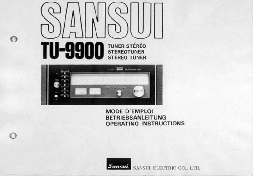
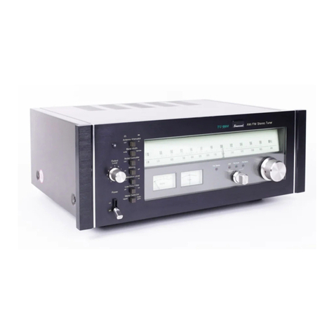
Sansui TU-9900 User manual

Sansui

Sansui TU-9900 User manual

Sansui TU 777 Troubleshooting guide

Sansui

Sansui TU 777 Troubleshooting guide

Sansui 1000X User manual

Sansui

Sansui 1000X User manual

Sansui T-700 User manual

Sansui

Sansui T-700 User manual

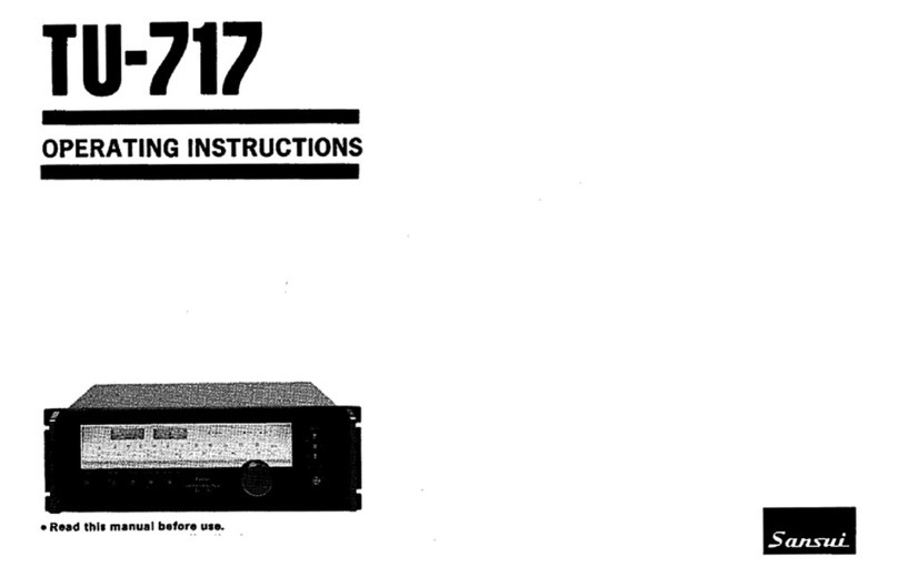
Sansui TU-717 User manual

Sansui

Sansui TU-717 User manual

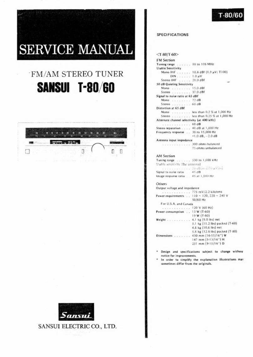
Sansui T-80 User manual

Sansui

Sansui T-80 User manual

Sansui TU-9900 User manual

Sansui

Sansui TU-9900 User manual

Sansui TU-666 Troubleshooting guide

Sansui

Sansui TU-666 Troubleshooting guide

Sansui tu-x701 User manual

Sansui

Sansui tu-x701 User manual

Sansui TU-505 Troubleshooting guide

Sansui

Sansui TU-505 Troubleshooting guide

Sansui TU-S77AMX User manual

Sansui

Sansui TU-S77AMX User manual

Sansui TU 777 Troubleshooting guide

Sansui

Sansui TU 777 Troubleshooting guide

Popular Tuner manuals by other brands

Technics ST-HD55 Service manual

Technics

Technics ST-HD55 Service manual

Arcam DT91 Handbook

Arcam

Arcam DT91 Handbook

HDHomeRun 20121008 installation instructions

HDHomeRun

HDHomeRun 20121008 installation instructions

Eico HFT-92 instruction manual

Eico

Eico HFT-92 instruction manual

MFJ MFJ-928 instruction manual

MFJ

MFJ MFJ-928 instruction manual

Teac T-1D Service manual

Teac

Teac T-1D Service manual

NAD C 445 owner's manual

NAD

NAD C 445 owner's manual

Sony ST-SA5ES operating instructions

Sony

Sony ST-SA5ES operating instructions

Pioneer GEX-P700DAB Operation manual

Pioneer

Pioneer GEX-P700DAB Operation manual

Sirius Satellite Radio SC-FM1 user guide

Sirius Satellite Radio

Sirius Satellite Radio SC-FM1 user guide

Antique Automobile Radio 283501B Installation and operating instructions

Antique Automobile Radio

Antique Automobile Radio 283501B Installation and operating instructions

Sanyo FMT M15L Service manual

Sanyo

Sanyo FMT M15L Service manual

Monacor PA-1200R instruction manual

Monacor

Monacor PA-1200R instruction manual

Technics ST-X301L Service manual

Technics

Technics ST-X301L Service manual

Manhattan 176156 user manual

Manhattan

Manhattan 176156 user manual

Marantz ST-15S1 user guide

Marantz

Marantz ST-15S1 user guide

Korg HA-40 owner's manual

Korg

Korg HA-40 owner's manual

Pioneer XC-IS21T Service manual

Pioneer

Pioneer XC-IS21T Service manual

manuals.online logo
manuals.online logoBrands
  • About & Mission
  • Contact us
  • Privacy Policy
  • Terms and Conditions

Copyright 2025 Manuals.Online. All Rights Reserved.

www.SteamPoweredRadio.Com
OPERATING
INSTRUCTIONS
STEREO TUNER
SANSUI
TU·
7700
SANSUI ELECTRIC
CO
., LTD.
www.SteamPoweredRadio.Com
We
are
grateful for your choice of the
Sansui
TU-7700
AM/FM
stereo tuner.
Before
you begin to operate it, may we
suggest
that you
read
this booklet of
operating instructions
as
well
as
the instructions sheet once carefully?
You
will
then
be
able to connect
and
operate it correctly,
and
enjoy its superb performance
for
years
.
eFUNCTIONAL
FEATURES
*
Smooth
tuning
feel.
The SIGNAL and TUNING meters
permit
instant and
accurate station
pinpointing
. The FM
STEREO
indicator
lights
up
to
let
you
know
when
the broadcast
you're
receiving
is
in
stereo.
*
Adjustable
output
level.
The set
is
equipped
with
an OUTPUT
LEVEL
control
on
the
front
panel,
you
can
match
the
output
level
of
the
tuner
with
that
of
any
other
program source (such
as
a deck
or
a
turntable),
connected
to
your
amplifier
. Therefore,
you
do
not
need
to
take
trouble
and adjust the
volume
control
when
switching
from
the
tuner
to
a tape deck
or
turntable,
or
vice versa.
*Extra conveniences
for
clear FM reception.
The set
is
provided
with
easily-accessible
front-panel
switches
for
steady and clear FM
reception.
The
FM
MUTING
and MPX NOISE
CANCELLER
switches
come
in
handy
for
those
living
in areas
where
signal strength
is
too
weak, i
.e.
the
locations
where
the desired station
may
be
very
far
or
where
tall
buildings
may be
dominating
the
ar
ea
. The
FM
ATTENUATOR
switch
is
for
those
who
liv
e
in areas
where
signal strength is
too
strong.
*
Devic
e
for
reduced
multipath
reception.
Switching
the
METER
SELECTOR
switch
to
MULTIPATH
lets the SIGNAL
meter
function
as
multipath
detection
meter
. You can thus easi
ly
orient
an
FM
antenna in a
direction
where
the
multipath
reflection
is
minimum
and
therefore
you
hear the
optimum
FM
re
ception
with
least
distortion
.
More
critical
multipath
check
is
possible
when
an
oscilloscope
is
connected
to
the
FM
MULTIPATH
OUT-
PUT
terminals on
the
se
t
's
rear panel.
*
Terminals
provided
for
two
different
types
of
FM
antennas.
Provisions are made
for
both
75-ohm and 300-ohm
FM
antenna terminals.
Connection
is
extrem
ely
simple
when
setting
up
an
outdoor
antenna using
either
a 75-ohm
unbalanced coaxial
type
lead-in cable
or
a 300-ohm
balanced feeder
type
lead-in cable.
----
Table of Contents
--------------------
IMPORTANT PRECAUTIONS
2
REAR-P
ANEL
CONNECTIONS 3
HINTS
FOR
BETTER
RECEPTION 4
OPERATING
PROCEDURES
5,
6
CONDITIONS
MIST
AKEN
FOR
BREAKDOWNS 7
INSTALLING
OUTDOOR
FM
ANTENNA CORRECTLY
8,9
SIMPLE
MAINTENANCE HINTS
10
SIMPLE
MAINTENANCE HINTS/SPECIFICATIONS
11
SCHEMATIC
DIAGRAM
12
www.SteamPoweredRadio.Com
I
1MPORTANT
PRECAUTIONS
To keep the set in
top
condition
all the time, observe
these precautions:
1.
Install the set
where
there
is
a
good
circulation
of
air.
2.
Avoid
an
extremely
hot
or
dusty place.
3.
If
the set
is
placed on a shelf, be sure
that
the shelf
board.
is
thick
and strong.
HEAT RADIATED
BY
THE
SET
As
transistors are sensitive
to
heat, the enclosure
of
this set
,is
designed
to
provide
a
good
dissipation
of
the heat radiated inside this set. Thus,
if
you
place
something on
top
the enclosure, place
the
set inside a
closed
box
and operate
it
for
many hours,
it
is
possible
that
the set
will
break
down
. Always
try
to
provide
sufficient
circulation
of
air around the set. But
removing
theenclosure
or
the
bottom
plate
to
allow
better
ventila-
tion
is
not
only
dangerous
but
undesirable
from
the
standpoint
of
electrical performance.
AC OUTLET
An AC
outlet
marked 'UNSWITCHED'
is
provided
on
the rear panel. The voltage
delivered
at this AC
outlet
is
the
same
as
the
power
supply
voltage used.
It
is
convenient
to
use
it
to
power
a program source such
as
your
turntable
or
tape deck.
It
has
a 150-watt
capacity
.
Do
not
connect
any
equipment
whose
power
consumption
exceeds the capacity
of
the
outlet,
as
it
is
extremely
dangerous.
-------------------------------------------------
2
www.SteamPoweredRadio.Com
HOW
TO
CONNECT
COAXIAL
CABLE
TO
FM
75n
TERMINAL
L
Loosen
Screws
I
t 1
Core Wire Tiahten
Screws
Shield
Coa•ial Cable (3C-2V)
OUTDOOR FM
ANTENNA
75
11
UNBALANCED
COAXIAL
CABLE
INDOOR
'T'
SHAPED
FM
ANTENNA
LEFT
DISCRIMINATOR
OUTPUT TERMINAL
(See
P-10)
AM FERRITE
BAR
ANTENNA
TO TAPEDECK,
ETC
.
CAUTION:
Never
connect
equip
-
ment
with
greater
power
requirements
than
specified maxi-
mum
rating.
~
WALL
AC
OUTLET
INTEGRATED
AMPLIFIER
RIGHT
SPEAKER
SYSTEMS
TAPE
DECK
(RECORDING)
(
Se
·e p.
IO
)
=LEFT CHANNEL
-RIGHT CHANNEL
3
----------------------------------------------
www.SteamPoweredRadio.Com
It
is
always
recommended
to
install
outdoor
antennas
so
that
you
may receive noise-free
FM
and
AM
broadcasts
with
optimum
tonal
quality
. You
will
find
an
outdoor
antenna-especially one
for
FM
-
particularly
effective
if
you are
remote
from
broadcasting trans-
mitters
or
surrounded
by
high mountains,
buildings
or
other
obsta-
cles.
OUTDOOR FM
ANTENNA
(
75
n)
750
UNBALANCED
COAXIAL
CABLE
Connect the
75!1
coaxial cable to the
AN
- ,
TEN
NA
FM
75n
terminal.
The
mesh
shield
1
of the coaxial cable
is
to facilitate electrical
connection with the metal fitting that holds
the cable (
The
mesh
is
held
by
the fitting
.)
OUTDOOR FM
ANTENNA
(
300
n)
3000
BALANCED
FEEDER
CABLE
Connect
300n
feeder cable to FM 30
0!1
antenna terminals.
OUTDOOR
AM
ANTENNA
Connect
PVC
cord to
AM
antenna terminal.
FM
300!1
AM
FM ANTENNAS
Outdoor
FM
antennas are
commercially
available
with
three, five
or
seven 'elements'. The
more
elements
an
antenna has, the greater distance
it
is
generally
intended
to
cover. You may connect
an
antenna
to
your
set
either
by
means
of
coaxial cable(75-ohm unbal-
anced)
or
feeder cable(300-ohm balanced). The
former
is
more
expensive
but
more
effectively keeps
out
external
noise-especially the
ignition
noise
of
nearby
automo-
biles-and transmit the signals
more
efficiently.
It
is
advised
that
you decide on the
type
of
antenna
and cable
to
use
after consultation
with
your
Sansui
dealer. Depending on the
type
of
antenna, you may
require
an
impedance matching transformer between
the antenna and the
connecting
cable, and this
too
should be
found
out
from
the dealer.
How
to connect:
Connect the antenna
to
your
set
as
illustrated in the diagram.
If
you are using coaxial cable, connect
it
to
the
FM
75,n terminals;
if
you are using feeder cable, connect
it
to
the
FM
300,n terminals.
(
Note
for Installing)
◊
To avoid
ignition
noise
produced
by
automobiles
and motor-cycles, install the antenna
as
far away
from
the street
as
possible.
◊
As
an
antenna
is
directional,
adjust its height and
direction
while
actually receiving
your
favorite
FM
station.
◊
Be
careful
so
that
the
antenna
or
the lead-in cable
does
not
touch
the electrical
power
line
around
your
house.
◊
It
is
always advisable
to
keep the lead-in cable
as
short
as
possible.
AM
ANTENNA
When
you
cannot
obtain
the desired results
by
using
the
AM
ferrite
bar antenna
only,
connect a
PVC
cord
to
the
AM
antenna terminal, extending
it
outdoors
if
pos-
sible.
GROUNDING
------~
If
you connect a
grounding
lead
to
the
ground-
ing terminal marked
GND
on the rear panel, the
noise contained in
radio
broadcasts may decrease.
It
may also keep external noises
from
creeping
into
the set.
The
grounding
lead may
either
be standard
PVC
cord
or
enameled
wire.
Attach a small
copper
plate
or
carbon
rod
to
its end, and
bury
it
deep
underground.
Or
if
there
is
a special
grounding
wire
or
terminal
in
your
room,
or
if
your
water
piping
is
of
iron,
the
grounding
lead may be con-
nected
to
them
.
NEVER
connect
it
to
your
gas
piping.
_________________________________________________
.:.;_
_ 4
www.SteamPoweredRadio.Com
1. POWER
CD
POWER Switch
Raise
the lever
switch
to
ON
to
turn the set on, push
it
down
to
OFF
to
turn
it
off
.
2. OPERATION OF THE
AMPLIFIER
Operate
your
amplifier
to
which
this set
is
connected
so
that
you
will
hear radio broadcasts.
3. BAND SELECTION
@
SELECTOR
Switch
This
switch
selects the band
(AM
or
FM) that you
want
to
hear.
AM: To receive
AM
broadcasts.
FM
AUTO: To receive
FM
broadcasts,
whether
stereo
or
mono
.
FM
MONO
:
If
the
FM
stereo reception
1s
too
noisy
for
pleasant listening, set the
switch
to
this
position
. The
broadcast
will
be received in
mono
but
the noise
will
be substantially decreased.
4. STATION SELECTION and
OUTPUT
LEVEL
ADJUSTMENT
@TUNING
Control
@
OUTPUT
LEVEL
Control
@ FM
MUTING
Switch
By
turning the TUNING
contro
l, first tune in the de-
sired station and adjust the OUTPUT
LEVEL
contro
l
to
attain a reasonably
loud
level. (Turn
it
clockwise
to
increase the level.) Fine-adjust the
output
level
when
the radio reception
is
optimized
. The OUTPUT
LEVEL
contro
l
is
to
be used
to
match the set's
output
signal
level
with
those
of
othe
r program sources (records,
tapes, etc.) on
equipment
connected
to
your
amplifier;
then you
do
not
need
to
adjust the
volume
of
your
amplifier
each
time
you
switch
the source selector
switch
or
tape
monitor
switch
on the
amplifier
.
To
tune
in an AM station,
when
the SIGNAL meter
deflects fully
to
the
right
whi
le
turning
the TUNING
control,
you
are receiving the station
with
optimum
ton-
al
quality
. Ignore the TUNING meter
while
tuning on
AM
.
To
tune
in an
FM
station, turn the TUNING
control
so
that the SIGNAL meter
pointer
may swing
as
far
to
the
right
as
possible and then
so
that
the TUNING meter
is
accurately centered. Then
you
are receiving the station
with
optimum
tonal quality. The set
is
tuned in on
an
FM
station broadcasting in stereo automatically, and the
FM
STEREO
indicator
lights.
When
tuning on the
FM
band, noise
is
usually heard
between stations
which
is
peculiar
to
FM
. Setting the
FM MUTING
switch
to
ON
cuts that noise and lets you
tune
quietly
.
If
you are
trying
to
tune in a weak station,
however, setting the
switch
to
ON
may cause the set
to
miss it. In that case,
it
is
better
to
push the switch
down
to O
FF
and then tune.
5
-----------------------------------------------
www.SteamPoweredRadio.Com
SIGNAL & TUNING
METERS
~---
Tune in the desired station while- observing these
meters. To
use
the SIGNAL meter
to
check the signal
strength, the
METER
SELECTOR
switch
must be at the
SIGNAL
position
. To
use
it
to
check the
multipath
re-
flection, the
switch
must be at the MULTIPATH
posi-
tion
.
FM
STEREO
INDICATOR
Lights
when
the set
is
tuned in on
an
FM
station
broadcasting in stereo.
• The numbers indicated in the
photograph
above
coincide
with
the
colored
switch
designations.
5.
CLEAR
FM RECEPTION
@ FM ANTENNA ATTENUATOR
Switch
This
switch
selects the
input
sensitivity
for
FM
stations.
It
should
normally
be at the
OUT
position
.
If
while
receiving
an
FM
station, located in
your
vicinity,
you
hear
too
coarse
or
distorted
reception due
to
exces-
sively strong signal strength,
however,
flip
the
switch
dow
n
to
I
N.
(j) MPX NOISE
CANCELLER
Switch
When
you hear
disturbing
noise
while
receiving
FM
stereo broadcasts, push the
switch
down
to
IN;
high-
frequency noise
will
then be suppressed and the
broad-
casts
will
sound
more
pleasant.
At
all
other
times,
however, the
switch
should be at its
OUT
position.
If
you should still hear noise even
when
the MPX
NOISE
CANCELLER
switch
is
IN, turn the
SELECTOR
switch
to
FM
MONO;
you should hear
less
noise,
though
in monaural.
eExcessive noise
is
often caused
when
the
incoming
signal
is
too
weak. Re-orientation
or
re-location
of
the
antenna may result in
improving
the reception
of
such
a weak signal.
@
METER
SELECTOR
Switch
To use the SIGNAL meter
to
check the signal strength,
this
switch
should be at the SIGNAL
position
. To
use
it
to
check the
multipath
reflection, this
swith
must
be pushed
down
to
MULTIPATH; you can
orient
the
antenna
for
the best
FM
reception.
The
radio
wave, used
for
FM
broadcast. possesses a
natural tendency
to
travel straight ahead and be re-
flected
by
various obstacles just
as
a Iight beam does.
As
a result,
an
antenna receives
both
the radio wave
arriving
directly
from
the broadcasting station and the
waves reflected
by
nearby mountains, tall buildings and
so
forth
.
(Multipath
reflection
. Refer
to
the page 8
for
details.)
When
this
condition
is
present, the radio waves
interfering
with
one another resul
ting
in amplitude and
phase
modulations,
and
distortion
and reduced separa-
tion
. To
minimize
this
condition,
it
is
necessary
to
orient
the antenna correctly.
You are rece
iving
optimum
FM
reception
with
the
least
multipath
phenomenon
when
the SIGNAL meter
deflects
fully
to
the
left
. Therefore, tune in
an
FM
station and then
turn
the antenna
until
the SIGNAL
meter
pointer
swings
as
far
to
the
l
eft
as
possible before
fixing it.
e
vou
can
orient
the antenna
more
critical
ly
if
you
have
an
oscillo
sc
op
e.
Refer
to
page 9.
----------------------------------------
6
www.SteamPoweredRadio.Com
Ma
ny
of
the
troub
l
es
which
seem
to
be a
fault
in the
set may be
ca
u
sed
by
wrong
operation
or
by
external
devices. These can be
easi
ly corrected
by
simple
checking and
easy
remedies. If you
notice
a
condition
which
looks like a
breakdown
of
the set, examine the
various connections and
your
operating procedure
once, then
look
up
the
condition
in the
following
chart
to
see
if it
cannot be easily removed.
If
this fails
to
improve
the
situation
and the set
definitely
seems
faulty, please
contact
the Sansui dealer
from
whom
you
purchased the set
or
your
nearest
Authorized
Sansui
Service Station.
PROGRAM
AM,
FM
or
MPX reception
FM
reception
SYMPTOM
PROBABL
E
CA
U
SE
* Constant
or
intermittent
noise heard at times
or
"in
certain
areas.
* Discharge or oscillation caused
by
electrical appliances, such
as
fluorescent lamp, TV set,
D.
C.
motor, rectifier
or
oscil-
lator.
* Noisy
* Natural atmospheric pheno-
mena
* Insufficient antenna
input
due
to
ferroconcrete structure
or
long distance
from
station.
* Poor noise
limiter
effect
or
too
low
S/N ratio due to ins
uf-
ficient
antenna
input
.
Note:
FM
reception
is
affected considerably by trans-
mitting
conditions
of
station, such
as
power
and
antenna efficiency.
As
a sesult, you may receive
one station
quite
well
while
receiving another
station
poorly
.
* A series
of
pops * I
gnition
noise caused by start-
ing
of
nearby
automobile
engine.
* Tu
ning
noise between sta- * Results
from
nature
of
FM
re-
tion. ception.
*
FM
MUTING switch at
OFF
.
FM-MPX reception * Noise heard
during
FM- * Weaker signal because service
area
of
FM-MPX broadcast
is
only
half
that
of
FM
mono
broadcast.
MPX reception
but
inaudi-
ble
duri
ng
FM
mono re-
ception.
AM
reception * Noise
hea
rd at particular
time
of
day, in certan area
or over part
of
dial.
* High-frequency noise.
* Peculiar to
AM
broadcasts.
*
Beat
interference
by
adjacent
station.
* TV set too close to stereo
sys-
tems.
WHAT TO DO
* Attach noise
limiter
to
electric
al
ap-
pliance producing noise, or attach
it
to set's
power
source.
* Install
outdoor
antenna and ground
set to improved S/N ratio.
*
Rev
e
rse
power
cord plug/receptacle
connections.
*
If
noise occurs at
ce
rtain frequency,
attach wave trap to
input
.
* Keep
set
at proper distance
from
other electrical appliances.
* Install antenna
for
maximum signal
strength.
*
If
this does
not
prove effective,
use
exclusive
FM
outdoor
antenna.
*
Exces
s
ively
long
lead-in
wire
of
an-
tenna may cause noise.
* Install antenna and its lead-in
wire
at proper distance
from
street
or
in-
crease antenna
input
.
* Turn on
FM
MUTING switch.
*
Orient
antenna
for
maximum antenna
input.
*
Set
MPX
NOISE
CANCELLER
switch to
IN position.
* Install antenna
for
maximum antenna
efficiency.
See
'AM
Antenna
'.
* In some
cases,
noise
can
be
eliminated
by
grounding tuner
or
reversing
power
cord plug/receptacle connections.
* Turn on
amplifier
's High Filter.
* Keep TV
se
t at proper distance
from
stereo system.
7
----------------------------------------------
www.SteamPoweredRadio.Com
WHAT
IS
MULTIPATH
REFLECTION?
As
the
radio
wave
used for
FM
broadcast
is
of
high
frequencies, it possesses a natural
tendency
to
advance
in
a straight line
and
be
reflected by various
obstacles
just as a light beam
does
.
As
result, an
antenna
receives
both
the
radio
wave
arriving directly from
the
broad-
casting station and
the
waves reflected by
nearby
moun-
tains, tall buildings
and
so forth. This
phenomenon
is
called a multipath reflection.
When
this
condition
is
present,
the
radio
waves inter-
fere
with
one
another
and
cause
amplitude
and
phase
modulation,
which
result
in
distortion
and
reduced
separation. To minimize this
condition,
it
is
necessary
to
select
an
antenna
with
good
directionality and also
orient
it correctly.
DIRECT
WAVE
&
REFLECTIONAL
WAVE
REFLECTIONAL
WAVE
J
_j
----
8
---------------------
-
-----------------------
www.SteamPoweredRadio.Com
HOW
TO
USE
FM MULTIPATH
OUTPUT TERMINALS
The
multipath
condition
can be visually observed
by
connecting
an
oscilloscope
to
the
FM
MULTIPATH
OUT-
PUT
terminals on the rear panel
of
the set,
so
that
you
may install the antenna in the correct
direction
.
The
two
terminals (indicated
as
V and H)
deliver
the
output
signals described
below
:
V:
Delivers the
detector
output
of
signals
amplitude-
modulated
by
the
multipath
reflection,
if
any.
If
no
multipath
reflection exists, no
output
will
be
provided.
H:
Delivers the set's
discriminator
output
signal, whose
level changes
with
the level
of
the original
audio
signal.
HOW
TO
CONNECT AND
OPERATE
AN OSCILLOSCOPE
1. Connect the oscilloscope
to
the
FM
MULTIPATH
OUTPUT terminals
as
indicated in the diagram
below
-
namely, its vertical axis
to
the V termin
al
and its
hori-
zontal axis
to
the H terminal.
2.
Tune in
your
favorite
FM
station accurately
while
watching
the SIGNAL and TUNING meters, and actually
receive it.
3.
Observe the
waveform
on the oscilloscope.
Set
the
horizontal
axis sensitivity
of
the oscilloscope
to
10mV/
cm
while
raising its vertical axis sensitivity
to
an
opti-
mum
level.
4.
Adjust
the
position
and
direction
of
the antenna and
fix
it
where
the
height
of
the
waveform
is
minimized.
See
a sample oscilloscope
waveform
as
below
.
SAMPLE
OSCILLOSCOPE
WAVEFORMS
OF
MUL
Tl
PATH
REFLECTION
When
no
multipath
reflecti
on
exists
When
a slight multipath
reflecti
on
exists
Adjust direction of antenna
so
as
to
minimize vertical
content of oscilloscope
waveform.
®
(®
1
□
[Q] 0
TU-7700
When
a seri
ous
multipath
reflection e
xi
sts
OSCILLOSCOPE
■
©
e-
~
I
I
VERTICAL
A
XI
S I
I
I
I
H
OR
IZ
ON
TAL
Ax
i
s-
I
I
I
I
I
------------
I
I I
'------------
--
--
------------'
9
-------------
--
------------------------------