OPTICAL TUNABLE FILTER OTF-920
1-1
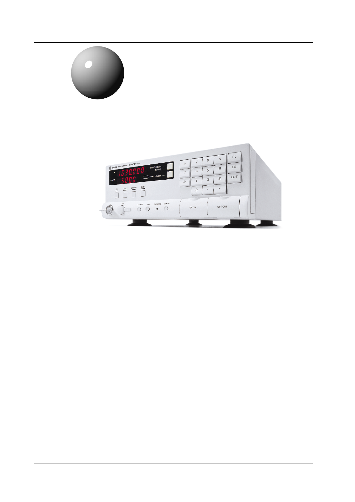
1Introduction
The OTF-920 has been designed to achieve exceptional optical performance whilst
maintaining flexibility and ease of use. t incorporates a multi-layer dielectric filter that has
been carefully fabricated to ensure high optical quality and long term stability. n addition,
the filter uses Santec’s unique linear sliding tuning technology which enables a wide tuning
range to be achieved, whilst the optical properties such as bandwidth, insertion loss, and
polarization dependent loss (PDL) are all wavelength independent.
The OTF-920 is particularly unique in that it has two optical sliders. This allows for
flexibility in configuration and operation. Each slider provides a 40nm tuning range and can
be configured with either a filter element or a variable attenuator. A combination of the two
sliders can thus provide: continuous tuning over a full 80nm, 40nm tuning but with two
separate bandwidths, or simultaneous control of wavelength and power using a combination
of filter element and attenuator in the sliders.
The OTF-920 boasts a very flexible peak search function that enables it to be used when even
multiple signals are present. This feature, combined with the GP B and RS-232C interfaces,
enable the filter to be used in a wide range of applications. The OTF-920 is easy to use, but
to obtain the most from your unit we recommend that you read this manual fully and become
familiar with its contents prior to operation. We hope that you will be satisfied with your
purchase.
Artisan Technology Group - Quality Instrumentation ... Guaranteed | (888) 88-SOURCE | www.artisantg.com