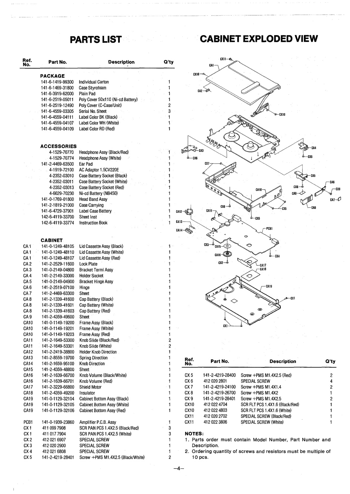
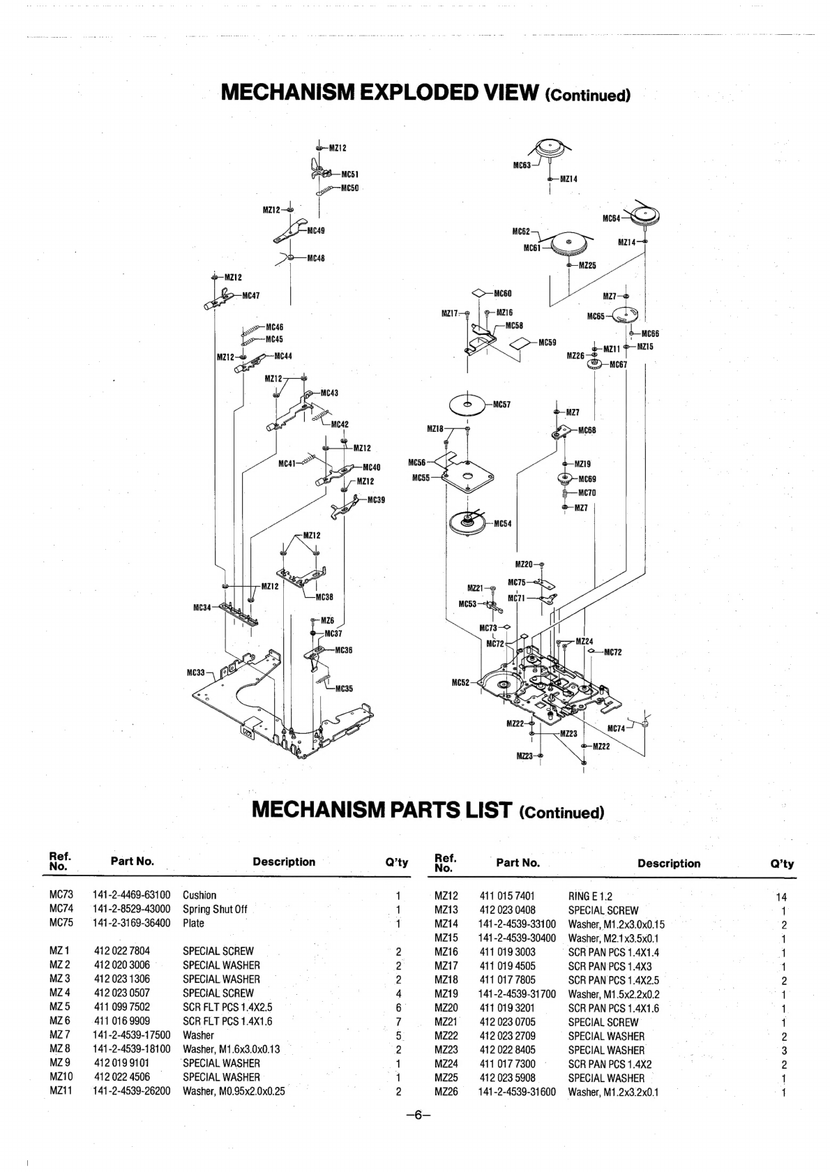
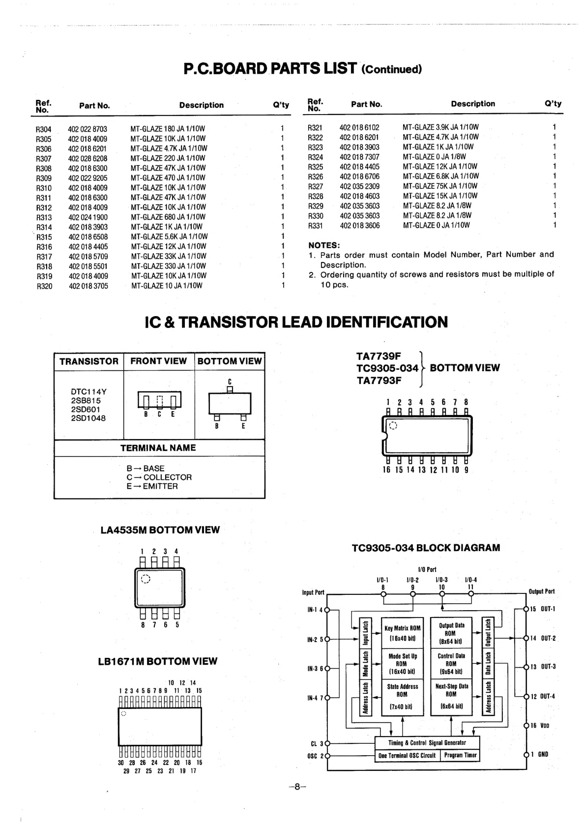
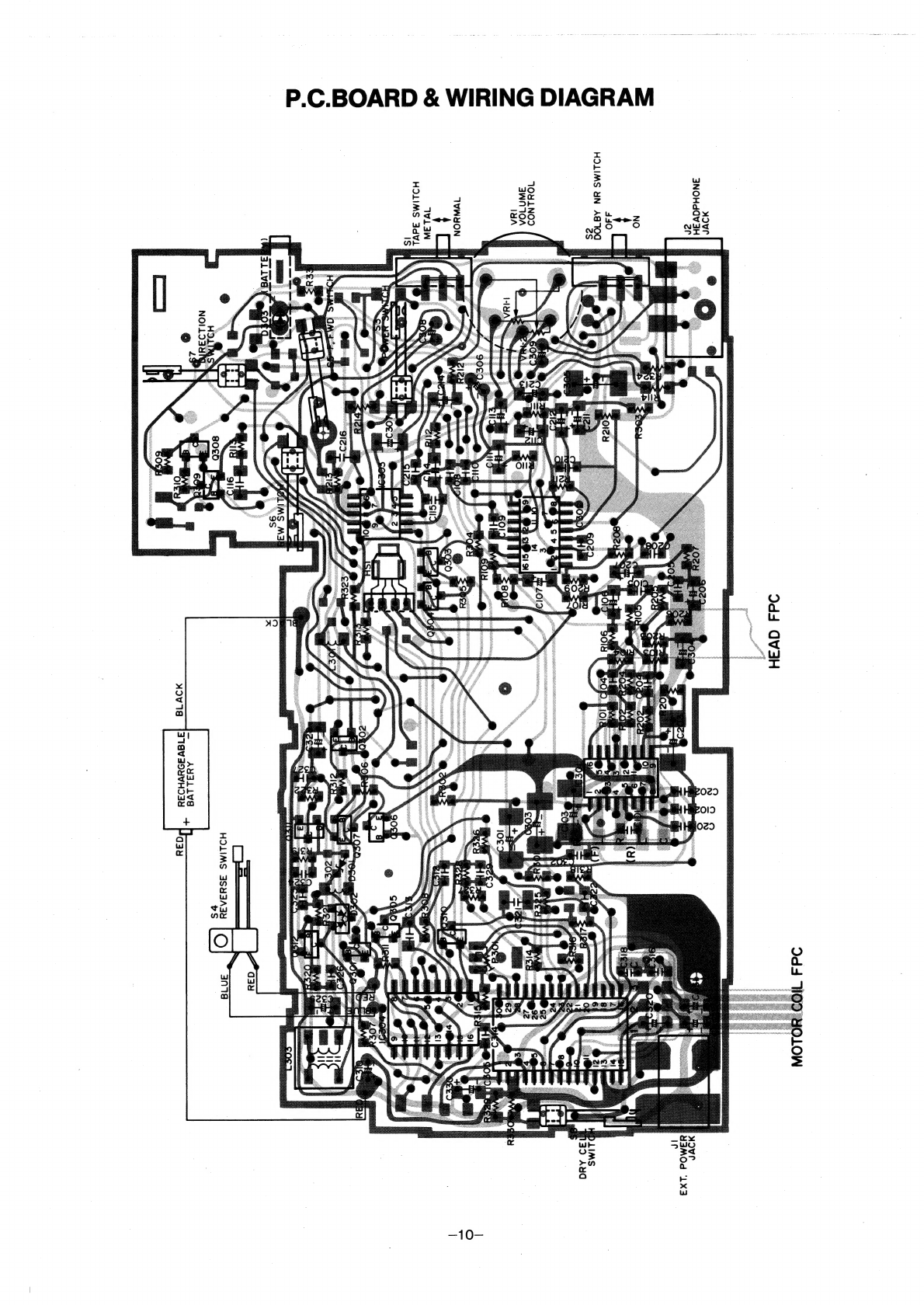
Sanyo JJ-P4 User manual

SERVICE
MANUAL
__
Ju
P4
(WEST
GERMANY)
STEREO
CASSETTEPLAYER
PRODUCT
CODE
No.
142473
26
(Black)
|
142
473
27
(White)
142
473
28
(Red)
SPECIFICATIONS
PowerSource
Wow
&
Flutter
.....
Pattneteees
weesees
0.6%,
RMS
DG
sath
dd
eenceaeniecnar
atest
1.5V
Frequency
Response
(P/B
Dolby
OFF)
|
Ni-cd
battery
..................0e
eee
NB-450
F208
00...
.cceeeeeeeeenereereesteres
638HZ~
10,000HZ
or
(UM-3,
HP
7,
AA
Cell,
Mignonzelle,
R
6)
x
1
Signal
to
Noise
Ratio
(w/Fe2O03)
...
More
than
42dB
Output
Power
.............0ceeeeeeee
es
3.5mW
x
2
(Max.)
Crosstalk
(w/Fe2O03)
Current
Consumption
(at
Vol.
Min.)
TRACK
10
TRACK
5
3.
seus
ceerenens
More
than
50dB
Playback
mode
.............0ceeeees
180mA
Channel
Separation
(w/Fe2O3)
....
More
than
20dB
Fast
Forward/Rewind
mode
......
300mA
Hum
&
Noise
(at
Vol.
Min.)
..........
—70dBs°
Tape
SOGCG"
35565
ceiir
ees
tcdsteeeees
ts
1-7/8ips.
£3%
.
Terminal
Impedance
ae
Fast
Forward/Rewind
Time.........
200sec.
(with
C-60)
Headphones
.............esceeeeeees
~8~
1000.
Torque
fe
8
PIAVDAOK
ntewaiciteirteseeoneentuses
25
~
40g-cm
|
Dimensions
(Max.)
........
69.8(W)
x
104.5(H)
x
18.5(D)mm
Fast
Forward/Rewind
.............
More
than
45g-cm
Weight
(w/o
batteries)
.............
2.
138g
—Specifications
subject
to
change
without
notice.—
A47500
REFERENCE
No.
WM-21014

GENERAL
REMARKS
@
Before.disassembling
the
unit,
spread
a
soft
rubber
mat
or
a
cloth
on
the
workbench
to
avoid
scratches
and
grease
stains.
@
Do
not
use
a
material
which
is
likely
to
cause
static
©
electricity
because
transistors
and
ICs
may
be
easily
damaged
by
it.
|
)
:
@
Reassemble
the
unit,
noting
the
kinds
of
screws,
the
soldering
and
arrangement
of
the
leads.
Refer
to
“Circuit
Diagram
and
Exploded
Views”
for
correct
assembly.
.
@
Before
disassembling
the
unit,
take
out
the
cassette
tape
and
the
batteries.
| |
e
Reassemble
in
reverse
order.
CABINET
BOTTOM
REMOVAL
|
1.
Remove
the
four
screws
(1
~
4)
fastening
the
CAbinet
Bottom
and
open
the
battery
compartment
lid.
2.
Detach
the
Cabinet
Bottom
by
lifting
it
in
the
direction
of
the
arrow.
tte
ts
|
Cabinet
Bottom
P.C.BOARD
REMOVAL
7
1.
Detach
the
Cabinet
Bottom,
and
unsolder
the
lead
wires
(black
and
red)
from
the
battery
terminals
and
the
Reverse
switch
leads
(red
and
blue)
from
the
switch.
2.
Remove
the
screw
(5)
detach
the
P.C.Board
by
lifting
it
in
the
directionofthearrow.
= =
#
© —
-
oe
_
DISASSEMBLY
INSTRUCTIONS
3.
Turn
over
the
P.C.Board
toward
the
back
of
the
unit
with
caution
not
to
damage
the
FPCs
of
the
Motor
and
Head.
FRAME
REMOVAL
“3.3
1.
Detach
the
P.C.Board,
and
remove
the
five
screws
(6
~
10).
ae
|
Detach
the
Frame
by
pulling
it
in
the
direction
of
the
arrow.
CASSETTE
LID
REMOVAL
|
1.
Detach
the
P.C.Board
and
Frame
adn
remove
the
screw
(11)
_
todetach
the
Hinge
Bracket.
2,
Remove
the
two
screws
(12
and
13)
and
detach
the
Cassette
Compartment
Lid
after
opening
the
Lid
by
pressing
the
STOP/EJECT
button.
Cassette
Compartment
Lid

ADJUSTMENT
PROCEDURES
GENERAL
REMARKS
,
|
@
Before
adjusting
the
mechanism
of
this
unit,
wipe
the
tape
@
This
model
features
the
Auto
Reverse
Mechanism.
Then
the
contacting
surfaces
clean
as
well
as
the
contacting
surfaces
tape
transport
direction
is
distinguished
as
follows:
of
the
driving
parts
with
a
cotton
swab
or
a
soft
cloth
soaked
=
FORWARD
DIRECTION:
in
alcohol.
Trouble
may
occur
because
of
oil
and
grease
The
tape
is
wound
counter-clockwise.
stains.
=
REVERSE
DIRECTION:
|
The
tape
is
wound
clockwise.
@
Handie
the
belt
carefully
the
because
grease
easily
attaches
_
z
se
|
to
it.
Then
check
the
used
rubber
parts.
If
the
rubber
has
@
When
performing
the
adjustment
while
sieve
pack
the
test
deteriorated
or
is
scratched,
replace
the
parts
with
new
one.
tape,
set
the
tape
transport
to
the
FORWARD
DIRECTION.
EQUIPMENT
REQUIRED
| |
@
FrequencyCounter
| ,
7
-_
@
Alignment
Tool
@
Dualtrace
Oscilloscope
,
|
-
NOTE:
e
VTVM
(2
sets)
OO
Before
the
Adjustments,
set
the
control
and
switch
as
follows:
@
Dummy
Load
(160)
- | |
=.
m
.
Dolby
NR
Switch
...................
aula
ascadaswastenacedaet
OFF
@
TestTapes
|
|
=
VolumeControl
......
eh
Ee
nee
Poe
ae
.....
AS
desired
°
3kHz
test
tape
(Example:
TEAC
MTT-
111)
=
Supply
the
regulated
DC
1
BV
power
to
the
Ext.
Power
Jack
es
10kHz
test
tape
(Example:
A:
BEX
TCC-1
53)
for
the
adjustment.
=»
ADJUSTMENT
PROCEDURE
Adjustment
Dummy
|
_
Measuring
_
Measuring
|
Tape
Speed
Speed
|
Frequency
Counter
|
|
Frequency
Counter
|
TEAC
MTT-111
|
MTT-111
P301
3,
|
3.000H2
3%
|
+3%
Headphones
pe
)
TM
oe
|
‘Oscilloscope
—-
Wavetorne
|
in
pies:
Potentiometer
for
Tape
Speed
Adjustment
Azimuth
Adjusting
Holes
Forward
Side
|
Reverse
Side

Ref.
No.
CA1
CA1
CA1
CA2
CA3
CA4
CAS
CA6
CA7
CA8
CA8
CA8
CA9
CA10
CA10
CA10
CA11
CA11
CA12
CAi3
CA14
CAIS
CA16
CA16
CA17
CA18
CA19
CAi9
CA19
PCBI
CX
1
CX1
CX
2
CX3
CX4
CX5
PARTS
LIST
—
Part
No.
PACKAGE
141-6-1419-99300
141-6-1469-31800
141
-6-3919-62000
141
-6-2519-05011
141-6-2519-12490
~
141-6-4559-03305
141-6-4559-04111
141-6-4559-04107
1471-6-4559-04109
ACCESSORIES
4-1529-70770
_.
4-4529-70774
141
-2-4469-63500
.
4-1919-72100
4-2352-03010
—-4-2352-03011
4-2352-03013
4-6629-70230
141-0-1769-01800
141-2-1819-21000
141-6-4729-37901
142-6-4119-33700
142-6-4119-33774
CABINET
144
-0-1249-48105
~
141-0-1249-48110
141-0-1249-48107
141-2-2529-11600
141-0-2149-04800
141-2-2149-33000
|
141-0-2149-04800
141-2-2519-07100
141-2-4469-63300
141-2-1339-41600
141-2-1339-41601
141-2-1339-41603
141-2-4359-49600
141-0-1149-19200
141-0-1149-19201
141-0-1149-19203
141-2-1649-53300
-
141-2-1649-53301
141-2-241
9-38800
141-2-8559-19700
141-2-1659-95100.
141
-2-4359-48800
141
-2-1639-66700
141
-2-1639-66701
141
-2-3229-66800
141-2-4359-49200
141-0-1129-32104
141-0-1129-32105
141-0-1129-32106
141
-0-1939-23860
411
099
7908
411
017
7904
412
021
6907
412
020
2900
412
021
6808
141
-2-4219-28401
Description
Individual
Garton
Case
Styrofoam
Plain
Pad
;
ost.
Poly
Cover
50x110
(Ni-cd
Battery)
Poly
Cover
(C-Case/Unit)
Serial
No.
Sheet
-
Label
Color
BK
(Black)
—
Label
Color
WH
(White).
Label
Color
RD
(Red)
Headphone
Assy
(Black/Red)
Headphone
Assy
(White).
Ear
Pad
AC
Adaptor
1.5CV220E
_
Case
Battery
Socket
(Black)
—
Case
Battery
Socket
(White)
Case
Battery
Socket
(Red)
|
Ni-cd
Battery
(NB450)
Head
Band
Assy
Case
Carrying
Label
Case
Battery
—
Sheet
Inst
Instruction
Book
Lid
Cassette
Assy
(Black)
Lid
Cassette
Assy
(White)
Lid
Cassette
Assy
(Red)
Lock
Plate
ss
Bracket
Termi
Assy
Halder
Socket
Bracket
Hinge
Assy
Hinge
Sheet
Cap
Battery
(Black)
Cap
Battery
(White)
Cap
Battery
(Red)
—
Sheet
_
Frame
Assy
(Black)
Frame
Assy
(White)
Frame
Assy
(Red)
—
Knob
Slide
(Black/Red)
Knob
Slide
(White)
Holder
Knob
Direction
.
Spring
Direction
Knob
Direction
Sheet
Knob
Volume
(Black/White)
Knob
Volume
(Red)
Shield
Motor
Insulator
Cabinet
Bottom
Assy
(Black)
Cabinet
Bottom
Assy
(White)
Cabinet
Bottom
Assy
(Red)
Amplifier
P.C.B.
Assy
SCR
PAN
PCS
1.4X2.5
(Black/Red)
SCR
PAN
PCS
1.4X2.5
(White)
SPECIAL
SCREW
SPECIAL
SCREW
SPECIAL
SCREW
Screw
+PMS
M1.4X2.5
(Black/White)
Q’ty
mos
—+-
wow
a
—4—
Ref.
CABINET
EXPLODED
VIEW
Description
|
No.
Part
No.
Q’ty
CX
5
141-2-4219-28400
Screw
+PMS
M1.4X2.5
(Red)
2
CX
6
412
020
2801
SPECIAL
SCREW
4
CX7
141-2-4219-24100
Screw
+PMS
M1.4X1.4
2
CX
8
141-2-4219-26700
Screw
+PMS
M1.4X2
1
CX9
141-2-4219-28401
Screw
+PMS
M1.4X2.5
2
CX10
412
022
4704
SCR
FLT
PCS
1.4X1.6
(Black/Red)
1
CX10
412
022
4803
SCR
FLT
PCS
1.4X1.6
(White)
1
CX11
412 020
2702
SPECIAL
SCREW
(Black/Red)
1
CX11
412
022
3806
SPECIAL
SCREW
(White)
1
NOTES:
1.
Parts
order
must
contain
Model
Number,
Part
Number
and
Description.
2.
Ordering
quantity
of
screws
and
resistors
must
be
multiple
of
10
pcs.

Ref.
No.
-
MC1
MC
2
MC
3
MC
4
MC
5
MC
6
MC
7
MC
8
MC
9
MC10
MC14
MC12
MC13
MC14
MC14
MC15
MC16
MC17
MC18
MC19
MC20
MC21
MC22
MC23
MC24
MC25
MC26
MC27
MC28
MC29
MC30
MC31
MC32
MC33
MC34
MC35
MC36
MC37
.
MC38-
MC39
MC40
MC40
MC41
MC42
MC43
MC43
MC44.
.
MC44
Mc45
MC46
MC47
MC47
MC48
MC49
MC50
MCc51
MC52
MC53
MC54
MC55
MC56
MC57
MECHANISM
PARTS
LIST
Part
No.
141-2-2899-13900
141-2-2899-23300
141-2-2899-19000
141-2-3519-85800
141-0-5519-15000
141
-0-5559-08400
141-0-7319-36800
141-2-8559-04000
141-0-5519-15200
141
-2-7439-56900
141-2-3529-54300
141-2-2529-11300
141-2-8529-42500
141-2-8529-42600
141-0-5459-03600
141
-2-5469-04500
141-0-3519-27000
141-0-3519-27001
141-2-8539-62400
141
-2-8549-41600
141
-2-8539-62500
141
-2-8559-18900
141-2-8559-19100
4-2429-73350
141
-2-8529-42400
141
-2-7539-91100
141
-0-7439-21
300
141-2-5469-04600
141-0-5459-03700
141
-2-8529-42700
141-2-2529-11200
141-2-3169-34800
141-2-5519-76500
141-2-5519-75600
141-2-4469-62900
141
-2-4469-62700
141-0-3129-02600
141-0-7539-00200
141-2-8549-42400
141-2-7319-88800
141-2-3529-54500
141-0-7539-00100
141-2-7429-07300
141-0-7359-021
00
141-0-7359-02101
141
-2-8549-12800
141-2-8549-04000
141-0-3759-02000
141-0-3759-02001
141
-0-7359-01900
141-0-7359-01901
141-2-8549-18000
141-2-8519-60600
141-0-7359-02000
141-0-7359-02001
141
-2-8529-42800
141-2-7439-57000
~
141-2-8549-41500
141-2-7439-57100
141
-0-3119-28201
4-2319-77690
141-0-3799-01
700
4-2649-70910
4-2262-35090
141-2-3799-04600
Description
CASSETTE
MECHANISM
Adhesive
Sheet
(for
Head
FPC,L)
Adhesive
Sheet
(for
Head
FPC,S)
Adhesive
Sheet
(for
Motor
FPC)
Plate
Trig
Pinch
Gear
Friction
Assy
.
Arm
Change
Assy
Base
Slide
Assy
Spring
Switch
Gear
Reel
FWD
Assy
Arm
Play:
|
Spacer
Arm
Play
Fix
Holder
R
SPG
Pinch
FWD
Spring
Arm
Pinch
Arm
Pinch
FWD
Assy
Roller
Pinch
FWD
Holder
Head
Assy
(Black)
Holder
Head
Assy
(White/Red)
Holder
R
|
Spring
Holder
Head
Holder
Lb
|
Spring
Spring
Play
Head
Assy
Spring
Arm
Base
PinAzimuth
Arm
Base
Assy
Roller
Pinch
REV
Arm
Pinch
REV
Assy
SPG
Pinch
REV
Fix
Holder
L
Panel
Chassis
Gear
Idle
Gear
Reel
REV
Sheet
Sheet
—
Chassis
Frame
Assy
Plate
Lock
Assy
Spring
Lid
Lock
Plate
Lock
Lid
Spacer
Lock
Lid
Plate
Switch
Assy
Lever
Eject
Rod
Stop
Assy
(Black/White)
Rod
Stop
Assy
(Red)
—
Spring
Lever
Play
Spring
Lever
Stop
Rod
Play
Assy
(Black/White)
Rod
Play
Assy
(Red)
Rod
Fast
Assy
(Black/White)
Rod
Fast
Assy
(Red)
Spring
Arm
Gear
|
Spring
Tension
Rod
Rewind
Assy
(Black/White)
—
Rod
Rewind
Assy
(Red)
7
Spring
Rod
Fast
Arm
Shut
Off
Spring
Arm
Mode.
ChassisAssy
Leaf
Switch
[S4/Reverse]
RotorComple
CoilAssy
=
FPC
Motor
Plate
Back-up
Q’ty
-
MECHANISM
EXPLODED
VIEW
Ref.
No.
MC58
MC59
MC60
MC61
MC62
MC63
MC64
MC65
MC66
MC67
MC68
MC69
MC70
MC71
MC72
@—NZI
Part
No.
141-2-3169-35200
141-2-4359-49500
141-2-4359-49400
141-0-661
9-00600
141-2-5649-31
000
141-2-5219-24500
141-2-5219-24400
141-2-5519-/76200
141-2-8259-15100
141
-2-5519-76300
141-0-5559-08300
141-2-5519-76400
141-2-8559-19800
141-2-8539-63400
141-2-4469-63200
Description
Shield
Motor
.
Sheet.
_
Sheet
Pulley
Assy
BeltDrive
Flywheel
REV
Flywheel
FWD.
Gear
Reverse
RollerREV
Gear
Idle
Reverse
Arm
Gear
Fast
Assy
Gear
Fast.
|
Spring.
Spring
Click
Cushion
Q’ty

_
MECHANISM
EXPLODED
VIEW
(continued)
_
b—wzi2
|
>—Mese
3
|
eee
|
|
mC49
b—MZ12
—MC47
o>
MCE
Meas
MZ12
a
an
MZ12
;
a
|
K-)
SS
mces—
|
b—MZ14
MECHANISM
PARTS
LIST
(Continued)
141-2-4539-31600
Washer,
M1.2x3.2x0.1
or
Part
No.
Description
—
Q’ty
hag
Part
No.
|
Description
Q’ty
MC73
=
141-2-4469-63100
Cushion
1
MZ12
~~
4110157401
RING
E
1.2
14
MC74
—-
141-2-8529-43000
Spring
Shut
Off
1
MZ13
412.023.0408
SPECIAL
SCREW
—
|
af
MC75
~—-
141-2-3169-36400
Plate
|
a)
MZi4
—_
141-2-4539-33100
Washer,
M1.2x3.0x0.15
29
a
:
a
MZ15
—
141-2-4539-30400
Washer,
M2.1x3.5x0.1
1
MZ
1
412
022
7804
SPECIAL
SCREW
<9
MZi6
411
019
3003
~
SCR
PAN
PCS
1.4X1.4
4
MZ2
4120203006
SPECIAL
WASHER
o
MZ17
=
411.019
4505
SCR
PAN
PCS
1.4X3__
4
MZ3
412023
1306
SPECIAL
WASHER
2
MZi8
411
017
7805
SCR
PAN
PCS
1.4X2.5
_
2
MZ4
412023
0507
SPECIAL
SCREW
4
MZ19
141-2-4539-31700
Washer,
M1.5x2.2x0,2
a
MZ5
411
099
7502
SCR
FLT
PCS
1.4X2.5
6
MZ20
411
019
3201
SCR
PAN
PCS
1.4X1.6
see
MZ6
~—s-
411
016.
9909
SCR
FLT
PCS
1.4X1.6
oe:
MZ21.
412.023.0705
SPECIAL
SCREW
1
MZ7
—-
141-2-4539-17500
Washer
|
5
MZ22
412023
2709
~
SPECIAL
WASHER
—
2
MZ8
—
141-2-4539-18100
Washer,
M1.6x3.0x0.13
2
MZ23.
412.022
8405
SPECIAL
WASHER
3
MZ9
412019
9101
‘SPECIAL
WASHER
1
MZ24
4110177300
-
SCRPANPCS1.4x2
2
MZi0
412022
4506
SPECIALWASHER
1
MZ25
412.023
5908
SPECIAL
WASHER
~
.
MZi1
—_
141-2-4539-26200
Washer,
M0.95x2.0x0.25
2
MZ26
4

Ref.
No.
PCB
J1
J2
$1
$2
$5.
56
S7
58
L301
—
L302
L303
P301
VR
1
HS
1
D301
D302
D303
-
10301
IC302
10303
1C304
10305
0301
0302
Q303
~
Q304
Q305
Q306
Q307
Q308
Q309
Q310
Q311
Q312
C101
C102
C103
C104
C105
C106
C107
C108
C109:
C110
C111
C112
C113
C114
C115
C116
C201
C202
C203
C204
C205
C206
C207
C208
—
C209
Part
No.
Description
AMPLIFIER
P.C.B.
ASSY
>
141
-0-1939-23860
141-2-1329-22600
141-2-4359-49600
141-2-4359-49800
141-2-4469-63000
4-2352-03140
|
4-2352-03130
4-2319-79320
—4-2319-79320
4-2312-06520
4-231
2-06510
4-2312-06510
4-2312-06510
-
4-2312-06510
~
4-2539-72313
4-2539-72313
4-2589-/3700
4-2229-77411
4-2229-/6690
407
090
7009
407
089
1605
407
008
5400
407
089
1407
409071
6407
©
409
119
1609
409
081
7104
409
115
8909
409
119
1500
405
034
9508
405
034
9508
405
008
7707
405
034
9508
405 034
9508
405 034
9508
405
008
7707
405
008
7707
405
034
9508
405
034
9508
-
405
024
3509
405
021
2406
403
074
9502
403
074
9502
404
012
7208
403
068
2007
403
068
1505
403
089
5308
-
403
089
5308
403
075
5305
403
0730005
-
403
067
9304
403
090
3201
403
091
8809
403
089
6206
-
403.090
3201,
403
0691702
403
068
0508
403
074
9502
403
074
9502
—
404012
7208
403
068
2007
~
403.068
1505
403
089
5308
403
089
5308
403
075
5305
403
073
0005
Amplifier
P.C.B.
Assy
Holder
Sensor
(for
HS1)
Sheet
.
sheet
-
Spacer
Ext.
Power
Jack
Jack
3P
Green
(Headphones)
Slide
Switch.
(Tape
Select)
Slide
Switch
(Dolby
NR)
Leaf
Switch
(Power)
Leaf
Switch
(F.FWD)
Leaf
Switch
(Rewind)
Leaf
Switch
(Direction)
.
Leaf
Switch
(Dry
Cell)
Chip
Coil
10H
K
Chip
Coil
10#H
K
OSC
Trans
D/D
Potentiometer
(B-3kQ)
Volume
Contro!
(A-20kO
x2)
.
SENSOR
SHS320-52
ZD
02CZ3.3X(TE85R)
DIODE
MA151WK-TW
LED
GL2PR9
(Battery).
-
IC
TA7739F(TP1)
IC
TA7793F(TP1)
IC
LA4535M-TP-T1
IC
TC9305-034
IC
LB1671M-T1P-T1
TRDTC114-YK
TR
DTC114-YK
TR
25B815-B7-TA
TRDTC114-YK
-
—TRDTCI14-YK
TRDTC114-YK
TR
2SB815-B7-TA
TR
2SB815-B7-TA
|
TR
DTC114-YK
TR
DTC114-YK
TR
2SD601-R-TW
TR
2SD1048-X7-TA
CERAMIC
680P
K
50V
CERAMIC
680P
K
50V
TA-SOLID
22U
M
4V
CERAMIC
0.022U
K
25V
CERAMIC
0.018U
K
25V
TA-SOLID
2.2U
M-4V
_
TA-SOLID
2.2U
M
4V
__
CERAMIC
8200P
K
50V
CERAMIC
3300P
K
50V
|
CERAMIC
0.01U
K
25V
TA-SOLID
1U
M
10V
TA-SOLID
0.47U
M
25V
TA-SOLID
4.7U
M
4V
TA-SOLID
1U
M
10V_
CERAMIC
1000P
K
50V
-
CERAMIC
0.1U
Z
25V
CERAMIC
680P
K
50V
©
CERAMIC
680P
K
50V_
TA-SOLID
22U
M
4V
~
CERAMIC
0.022U
K
25V
CERAMIC
0.018U
K
25V_
TA-SOLID
2.2U
M
4V
TA-SOLID
2.2U
M
4V
CERAMIC
8200P
K
50V
CERAMIC
3300P
K
50V
Q’ty
Ref.
No.
C210
C211
C212
C213
C214
C215
C216
C301
C302
C303
C304
C305
C306
C307
C308
C309
C310
C312
C313
C314
C316
©
C318
C320
C321
C322
C323
C324
C325
6326
C327
C328
C329
C330
-
C331
C332
R101
R102
R103
R104
R105
R106
~
R107
R108
R109
R110
R111
R112
R113
R114
R201
R202
R203
R204
R205
R206
R207
R208
R209
R210
R211
R212
R213
R214
R301
R302
R303
P.C.BOARD
PARTS
LIST
Part
No.
403
067
9304
403
090
3201
403
091
8809
403
089
6206
403
090
3201
403
069
1702
403
068
0508
404
012
7208
403
069
1702
404
012
7208
404
028
7308
404
012
7208
403
038
0705
404
028
7308
403
038
0705
4-2239-71961
4-2239-/1961
403
068
1000
403
068
0508
403
068
0409
403
068
0409
—
403
068
0409
403
090
3201
~
404031
0808
403
067
9304
403
068
2007
403
068
2007
404
028
7308
-
403
073
0005
403
068
2007
404
028
7308
403
067
9304
403 089
5605
403
089
5605
403
089
5605
402
018
3804
—
402
018
6706
402
018
4108
~~
402.018
4900
402
018
6102
402
018
5600
4020185709
402
018
5709
402
018
5709
402
035
2101
.
©
402
023
3202
402
018
3903
402
018
5402
402
018
7307
402
018
3804
402
018
6706
402
018
4108
402
018
4900
402
018
6102
402
018
5600
402
0185709
402
018
5709
402
018
5709
402
035
2101
402
023
3202
402
018
3903
402
018
5402
402
018
7307
402
018
3903
402
018
3804
402
018
4801
Description
—
CERAMIC
0.010
K
25V
TA-SOLID
1U
M10V
TA-SOLID
0.47U
M
25V
--TA-SOLID
4.7U
M
4V
—
TA-SOLID
1U
M
10V
CERAMIC
1000P
K
SOV
CERAMIC
0.1U
Z
25V
TA-SOLID
22U
M
4V
_
CERAMIC
1000P
K
50V
~
TA-SOLID
22U
M
4V
TA-SOLID
10U
M
4V
TA-SOLID
22U
M
4V.
ELECT
47UM4V
-
~
TA-SOLID
10U
M
4V.
ELECT
47U
M
4V
Capacitor
CD
220F
4V
Capacitor
CD
220F
4V
CERAMIC
0.012U
K
25V
CERAMIC
0.1U
Z
25V
CERAMIC
0.1U
Z
25V
~
CERAMIC
0.1U
Z
25V
CERAMIC
0.1U
Z
25V
TA-SOLID
1U
M
10V
CERAMIC
0.47U
Z
50V
CERAMIC
0.01U
K
25V
CERAMIC
0.022U
K
25V
CERAMIC
0.022U
K
25V
TA-SOLID
10U
M
4V
CERAMIC
3300P
K
50V
CERAMIC
0.022U
K
25V
-TA-SOLID
10U
M
4V
CERAMIC
0.01U
K
25V_
TA-SOLID
3.3U
M
4V_
TA-SOLID
3.3U
M
4V
TA-SOLID
3.3U
M
4V
MT-GLAZE
100
JA
1/10W
MT-GLAZE
6.8K
JA
1/10W
MT-GLAZE
100K
JA
1/10W
MT-GLAZE
180K
JA
1/10W
MT-GLAZE
3.9K
JA
1/10W
MT-GLAZE
3.3K
JA
1/10W
MT-GLAZE
33K
JA
1/10W
MT-GLAZE
33K
JA
1/10W
MT-GLAZE
33K
JA
1/10W
MT-GLAZE
13K
JA
1/10W
MT-GLAZE
390K
JA
1/10W
MT-GLAZE
1K
JA
1/10W
MT-GLAZE
3.9
JA
1/10W
MT-GLAZE
0
JA
1/8W
MT-GLAZE
100
JA
1/10W
MT-GLAZE
6.8K
JA
1/10W
MT-GLAZE
100K
JA
1/10W
MT-GLAZE
180K
JA
1/10W
MT-GLAZE
3.9K
JA
1/10W
MT-GLAZE
3.3K
JA
1/10W.
MT-GLAZE
33K
JA
1/10W
MT-GLAZE
33K
JA
1/10W
MT-GLAZE
33K
JA
1/10W
MT-GLAZE
13K
JA
1/10W
MT-GLAZE
390K
JA
1/10W
MT-GLAZE
1K
JA
1/10W
MT-GLAZE
3.9
JA
1/10W
MT-GLAZE
0
JA1/8W
_
MT-GLAZE
1K JA
1/10W
MT-GLAZE
100
JA
1/10W
MT-GLAZE
18K
JA
1/10W
Q’ty

P.C.BOARD
PARTS
LIST
(Continued)
‘be
Part
No.
Description
Q’ty
ee
Part
No.
Description
Q’ty
R304
402022
8703
MT-GLAZE
180
JA
1/10W
1
R321
402
018
6102
MT-GLAZE
3.9K
JATMOW
1
R305
402 018
4009
MT-GLAZE
10K
JA
1/10W
|
R322
402
018
6201
MT-GLAZE
4.7K
JA
1/10W
©
:
R306
402
018
6201
MT-GLAZE
4.7K
JA
1/10W
1
R323
402
018
3903
MT-GLAZE
1K
JA
1/10W
1
R307
402
028
6208
MT-GLAZE
220
JA
1/10W
1
R324
402
018
7307
MT-GLAZE
0
JA
1/8W
1
R308
402
018
6300
MT-GLAZE
47K
JA
1/10W
1
R325
402
018
4405
MT-GLAZE
12K
JA
1/10W
1
R309
402 022
9205
MT-GLAZE
470
JA
1/10W
|
R326
402
018
6706
MT-GLAZE
6.8K
JA
1/10W
1
R310
402
018
4009
MT-GLAZE
10K
JA
1/10W
1
R327
402
035
2309
MT-GLAZE
75K
JAT/MOW
|
4
R311
402
018
6300
MT-GLAZE
47K
JA
1/10W
+
R328
402 018
4603
MT-GLAZE
15K
JA
1/10W
1
R312
402
018
4009
-MT-GLAZE
10K
JA
1/10W
1
R329
=
402.035
3603
MT-GLAZE
8.2
JA
1/8W
1.
R313
402 024
1900
MT-GLAZE
680
JA
1/10W
1
R330
402
035
3603
MT-GLAZE
8.2
JA
1/8W
1
R314
402
018
3903
MT-GLAZE
1K
JA
1/10W
1
R331
402
018
3606
MT-GLAZE
0
JA
1/10W
1
R315
402
018
6508
MT-GLAZE
5.6K
JA
1/10W
|
.
R316
402 018
4405
MT-GLAZE
12K
JA
1/10W
1
NOTES:
R317
402 018
5709
MT-GLAZE
33K
JA
1/10W
4
1.
Parts
order
must
contain
Model
Number,
Part
Number
and
R318
402
018
5501
MT-GLAZE
330
JA
1/10W
1
Description.
R319
402
018
4009
-MT-GLAZE
10K
JA
1/10W
1
2.
Ordering
quantity
of
screws
and
resistors
must
be
multiple
of
R320
402
018
3705
~
MT-GLAZE
10
JA
1/10W
1
7
10
pcs.
IC
&
TRANSISTOR
LEAD
IDENTIFICATION
TRANSISTOR
BOTTOM
VIEW
TA7739F
— :
——
TC9305-034
}
BOTTOM
VIEW
TA7793F
DTC114Y
3
2SB815
| |
2SD601
us
Visesers
28D1048
TERMINAL
NAME
B—
BASE
C—
COLLECTOR
E—
EMITTER
16
151413121110
9.
-
LA4535M
BOTTOM
VIEW
|
TC9305-034
BLOCK
DIAGRAM
1/0
Port
/0-1
10-2
VO-3-
~—«*W0-4
8
iW
,
S
Output
Port
15
OUT-1
Output
Data
ROM
{8x64
bit)
LB1671M
BOTTOM
VIEW
7
ae
Up
se
ha
|
(16x40
bit)
(9x64
bit)
Key
Matrix
ROM
(16x40
bit)
14.
OUT-2.
13
OUT-3
10
2
14
|
State
Address
Next-Step
Data
| :
12
OUT-4_
(7x40
bit)
(6x64
bit
im
Address
Latch
}
Data
Latch
|
Output
Latch
O16
VoD
Timing
&
Control
Signal
Generator
One
Terminal
OSC
Circuit
O1
GND
29
27
25
23
21
19
7

IC
&
TRANSISTOR
LEAD
IDENTIFICATION
(Continuea)
TA7739F
BLOCK
DIAGRAM
,
LA4535M
BLOCK
DIAGRAM
TA7793F
BLOCK
DIAGRAM
B-INB
=—-—-
EK--INB
OUTB
VR-INB
HPFB
LPFB
SW
vec
LB1671M
BLOCK
DIAGRAM
Vref
(0.5¥)
osc
DR
SIN
(—)
IN2(-+)
23
15
30
28
29
e
®
1
2
8 6
§
4
9
8
7
12
=I
10 13
«620619
17 16
Vcc
Logic
Power
PW BW
W
PU
OU.
U
PV
DV
V_
Power
VSP
IN+
OUT
Al
GND
GND
7
GND

P.C.BOARD
&
WIRING
DIAGRAM
Move
3NOHdOV3H
er
NO
-
440
HOLIMS
YN
AS17100
2S
TOYLNOD
3JWNIOA
IMA
HOLIMS
advi
is
AY3ZLLV8
3T8V
S9YVHI3SY
+)
HOLIMS
3SY3A3u
vS
Mover
aAMod
‘LX3
DLIMS
33
AYOd

SCHEMATIC
DIAGRAM
‘VOEDI
JO
|b
Uld
0}
(AG"
L)G+
84}
Bulppe
pue
pieog’d'd
84}
BulAowss
Aq
pa}inseJ
paunseew
s!
a6e}/0A
ey
440
YOUMS
1189
Aug
-ALON
440
YOM
UO}OesIq
ede
|
AdsdO
YOUMS
PUuIMeYy
440
YOUMS
GM'S
4AO
YD}UIMS
8SJaAeY
dAdO
YOUMG
JOMOd
4AdO
YOUMS
YN
Aqiog
IWNYHON
YOUMS
JO9jag
ede]
(
)3NO
037
{(AuBLiVa)
T
LINDYID
SANG
Jaq
eee
YOLYZANOD
90/90
=
:
AvpllOLGs®®
SISESz
s0e0
iciue
ttt:
logasz'=
spolasz
ze
AbioLaoe
aT
ee
Tease
739
Aud
ae
@
I
T
wok
tzzooL
sic
6lgy
peed
eareg
|
l
wee
ZISY
fe
od
at
aa
ime
:
Move
Y3AMOd
‘LX3
~=—
Mab
Ap
Lb
MI
a
Zl
sl
6l_ti«éM
l@
@
€&
ve
se
92
22
82
6
O¢
rzzoor
Nol
eeey
icy
.
0
2zeo]
8zed}
—
ao
“A
re
PS
so¢di
eeu
a
sit
gl
ZI
UI
ol
6
8
Z
9
S
b
¢
Z
1
0A
=
+]
AOL
AO
Aol
AST
Apts
ASI]
Asi]
ably
ASI]
ASIT
Ap]
y
Asi
AO
AO
HAMS
f£¢00'0
‘tio
|
Lage
|
isso]
fade
7
Hanod
92¢9
ozed
zeed
1ge9
O€ED
_|
Av
2
uske)
w10
piece
ged
a)
LINDYID
IONLNOD
WSINVHOSW
GOEG6OL
POF?!
LINDYID
SANG
YOLOW
WI29187T
9°€>!
HILIMS
3SY3A34N
vs
APHIL|
Soe
“ams
y
‘ABU
tsi00
§=—
NE.
OZ)
soy
(A'ZW)
AON
00'0
GID
Move
INOHddV3H
oe
ONLNOD
nae
“y=
AWNMIOA
1
Aol
ml
PHD
=
ily
‘OM4
I
cir
QV3H
AVId
wee
+
-
yee
10H
8014
Zold
90ID
9018
t2Z0'0
YaIsIIdWV
Y3MOd
a+
void
WSESpVv7
£°F>!
ogi
oo!
LINDYID
YN
ABTI00
;
vOeHYy
zoey
YalsIIdWY
3Yd
ACELLVLF9!
AGELZZVL
10291

REFERENCE
VOLTAGES
iC301
"Pa
Ps
Te
ser
Ps
Po
ro
a
as
a
as
Forward
|
21
[14
[it
[it
[ii
[it
|
o
|
o
[oo
[i412]
0 |
o
|
o
[12
|
it
|
[Reverse
|»
|»
|»
|
|»
|»
[22].
|»
|»
|e
|
| |
|
|e
|
Metal
te
te te
Pe
te
te
te
et
Pe
fet
fl
TY
re
23
A$
6
BS
tt
2
minicar
alee
a
DomyOre
aes
|
we
Lato
Leow
oe
hoe
ee
IC303
Pet
8a
sé
16
7]
8
8
10.
Playback
|
15
[08
|
0
|
08
[08
115
|o6
|
0
|
06
[14
|
ar
(2/3
)4
[5/6/71]
8
{9
[10111/12/13
114
[15
|
16
|
Pavear
[ois
es
[os
[estes
testo[estotisto
te
te
ole
1C305
po
et
ta
ts}
)]
tz]
8
|
8
[10]
14]
12/13
[14
|
15
|
Playback
|
15
[0
|
o
115
|
o
[15
]45]
0
[15
[15]
0115]
0 |
o
|
0
IC305
[16
717 [18 [19 [20 [21
[227
23
[24 [25
[26]
27
[28
[29
30,
Playback
|
0
| 0
|
of
o
jo
fis
}o]o
|
oo
jos)
25
|o2}o2}
o
|
@3o1_—
|
=
a303_—
|
307
|
31
|
312
1Bicile{pepicijeisaicle{saici{elsicile
|
Forward
|
25
|
0
|
0
|
18
|
25
|
25
[08
|
15
|
15
|
06
|
02|
0
|
02
|
26
|
0
|
[Reverse
|
25
[22]
0]
»[»|»|»{»i[~{[»|[~{-[»j
+
]»|
|
asos_—
|
=
a309
.Bi|cilelspicl|e
|
JLEDON
|
18
|
24
|
24/12
|
0
|
0
[LEDOFF
|
25]
0
|
26]
0
|
25)
+
|
NOTE:
The
Voltage
is
measured
resulted
by
removing
the
P.C.Board
and
adding
the
+B(1.5V)
to
Pin
11
of
IC304.
SANYO
Electric
Co.,
Ltd.
OSAKA,
JAPAN
July/’87/500/H
Printed
in
Japan
This manual suits for next models
3
Table of contents
Other Sanyo Cassette Player manuals

Sanyo
Sanyo MCD-Z31F User manual

Sanyo
Sanyo ES-P7 User manual

Sanyo
Sanyo MCD-Z8F (AU) User manual

Sanyo
Sanyo M4440 User manual

Sanyo
Sanyo MCD-S660F User manual

Sanyo
Sanyo M9930K User manual

Sanyo
Sanyo MR-410 User manual

Sanyo
Sanyo CWM-240 User manual

Sanyo
Sanyo MCD-Z110F User manual

Sanyo
Sanyo MCD-ZX680M/XE User manual

Sanyo
Sanyo MCD-Z260F User manual

Sanyo
Sanyo M1990FE User manual

Sanyo
Sanyo M7770K User manual

Sanyo
Sanyo MCD-Z250F User manual

Sanyo
Sanyo MCD-S670F User manual

Sanyo
Sanyo MCD-S860F User manual

Sanyo
Sanyo M7900K User manual

Sanyo
Sanyo TRC-960C User manual

Sanyo
Sanyo TRC 8000 User manual

Sanyo
Sanyo TRC-7060 User manual