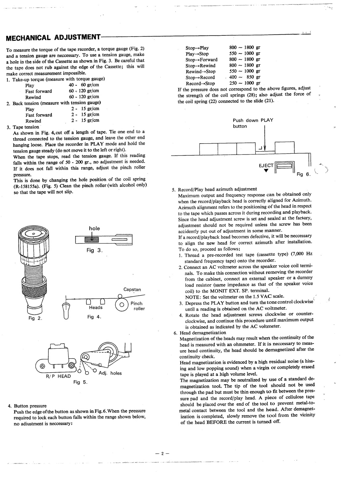
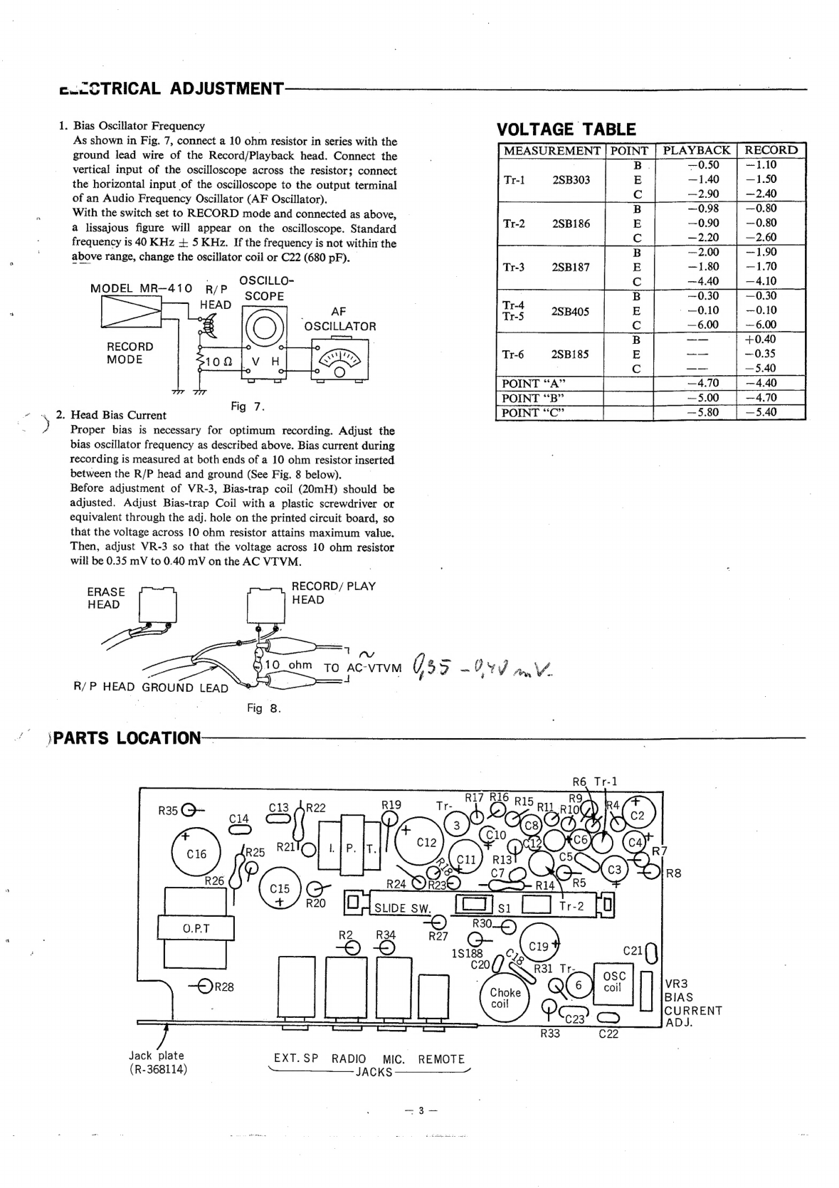
Sanyo MR-410 User manual

All
fasteners
subject
to
metric
dimension
of
International
Orga-
nization
for
Standardi-
zation.
.
Portable
Cassette
Recorder
MODEL
MR-410
SERVICE
MANUAL
SANYO
ELECTRIC
CO.,
LTD.
INTERNATIONAL
DIVISION
:
SANYO
ELECTRIC
TRADING
CO.,
LTD.
OSAKA,
JAPAN
‘SPECIFICATIONS
Recording
system
AC
bias,
double
track
Frequency
response
50
to
10,000
Hz
.
Erasing
system
DC
erase
Transistors
|
25B303
x
I
2SB187
x
1
Tape
speed
1-7/8
ips.
(4.8
cm/sec.)
2SB186
x
1
2SB405
x
2
Recording
(playback)
2SB185
x
1
,
time
1
hour
(C-60)
Diodes
1S188
x
1
181849
x
2
Rewind
and
fast
Thermistor
SDT-06
x
1
forward
time
1’
45”
(C-60)
Speaker
4”
(10
cm)
P.
D.
S.
8Q
Output
power
1.5W
max.
Power
source
AC;
120/200/240
V,
50/60Hz
multivoltage
Wow
and
flutter
0.3%
RMS
DC;
6V,
“C’’-size
(UM-2)
batt.
x
4
Signal
to
noise
ratio
40dB
Dimensions
6-7/16”(W)
x
2-13/16
“(L)
x
6-3/16"(H
Terminals
MIC.
10KQ
Weight
4.8
lbs.
AUXIN
270KQ
Accessories
Microphone,
audition
cassette,
AC
cord
EXT
SP
82
DISASSEMBLEY
INSTRUCTION——
To
remove
the
amplifier
and
mechanism
from
the
cabinet:
1.
Pull
out
the
Tone
and
Volume
control
knobs.
2.
Place
the
recorder
front
side
down
and
remove
the
screw
from
the
center
of
the
cabinet
back.
CABINET
BACK
PUSH
STRAIGHT
Jf
,
AND
LIFT
UP
3.
Depressing
the
cabinet
bottom
with
both
thumbs,
open’
the
FOR
CABINET
BACK
REMOVAL
FIRST
TAKE
OFF
THIS
SCREW
back
cabinet.
See
Fig.
1
below.
ll
-
PUSH
STRAIGHT
AND.
LIFT
UP
CABINET
FRONT
Fig
1.

MECHANICAL
ADJUSTMENT
To
measure
the
torque
of
the
tape
recorder,
a
torque
gauge
(Fig.
2)
and
a
tension
gauge
are
neccessary.
To
use
a
tension
gauge,
make
a
hole
in
the
side
of
the
Cassette
as
shown
in
Fig.
3.
Be
careful
that
the
tape
does
not
rub
against
the
edge
of
the
Cassette;
this will
make
correct
measurement
impossible.
1.
Take-up
torque
(measure
with
torque
gauge)
Play
40
-
60
gr/cm
Fast
forward
60
-
120
gr/cm
Rewind
60
-
120
gr/cm
2.
Back
tension
(measure
with
tension
gauge)
Play
2-
15
gr/cm
Fast
forward
2-
15
gr/cm
Rewind
2-
15-gr/em
3.
Tape
tension
"
|
As
shown
in
Fig.
4,cut
off
a
length
of
tape.
Tie
one
end
to
a
thread
connected
to
the
tension
gauge,
and
leave
the
other
end
hanging
loose.
Place
the
recorder
in
PLAY
mode
and
hold
the
tension
gauge
steady
(do
not
move
it
to
the
left
or
right).
When
the
tape
stops,
read
the
tension
gauge.
If
this
reading
falls
within
the
range
of 50
-
200
gr.,
no
adjustment
is
needed.
If
it
does
not
fall
within
this
range,
adjust
the
pinch
roller
pressure.
.
This
is
done
by
changing
the
hole
position
of
the
coil
spring
(R-158155a).
(Fig.
5)
Clean
the
pinch
roller
(with
alcohol
only).
so
that
the
tape
will
not
slip.
hole
Fig
3.
Capstan
R/P
HEAD
Fig
5.
4.
Button
pressure
|
Push
the
edge
of
the
button
as
shown
in
Fig.6.When
the
pressur
required
to
lock
each
button
falls
within
the
range
shown
below,
no
adjustment
is
neccessary:
scape
ea
a
—?—
.
Record/Play
head
azimuth
adjustment
Stop—Play
800
~
1800
gr
Play—Stop
550
~
1000
gr
Stop—Forward
800
~
1800
gr
Stop—Rewind
800
~
1800
gr
Rewind—Stop
550
~
1000
gr
Stop—Record
.
400
~
850
er
Record—Stop
250
~
1000
gr
If
the
pressure
does
not
correspond
to
the
above
figures,
adjust
the
strength
of
the
coil
springs
(28);
also
adjust
the
force
of
the
coil
spring
(22)
connected
to
the
slide
(21).
.
Push
down
PLAY
button
|
EJECT
Vv
Si
Fig
6.
Maximum
output
and
frequency
response
can
be
obtained
only
when
the
record/playback
head
is
correctly
aligned
for
Azimuth.
Azimuth
alignment
refers
to
the
positioning
of
the
head
in
respect
to
the
tape
which
passes
across
it
during
recording
and
playback.
Since
the
head
adjustment
screw
is
set
and
sealed
at
the
factary,
adjustment
should
not
be
required
unless
the
screw
has
been
accidently
put
out
of
adjustment
in
some
manner.
If
a
record/playback
head
becomes
defective,
it
will
be
neccessary
to
align
the
new
head
for
correct
azimuth
after
installation.
To
do
so,
proceed
as
follows;
1.
Thread
a
pre-recorded
test
tape
(cassette
type)
(7,000
Hz
standard
frequency
tape)
onto
the
recorder.
2.
Connect
an
AC
voltmeter
across
the
speaker
voice
coil
termi-
nals.
To
make
this
connection
without
removing
the
recorder
from
the
cabinet,
connect
an
external
speaker
or
a
dummy
load
resistor
(same
impedance
as
that
of
the
speaker
voice
coil)
to
the
MONIT
EXT.
SP.
terminal.
NOTE:
Set
the
voltmeter
on
the
1.5
VAC
scale.
3.
Depress
the
PLAY
button
and
turn
the
tone
control
clockwise
until
a
reading
is
obtained
on
the
AC
voltmeter.
4.
Rotate
the
head
adjustment
screws
clockwise
or
counter-
clockwise,
and
continue
this
procedure
until
maximum
output
is
obtained
as
indicated
by
the
AC
voltmeter.
.
Head
demagnetization
Magnetization
of
the
heads
may
result
when
the
continuity
of
the
head
is
measured
with
an
ohmmeter.
If
it
is
neccessary
to
meas-
ure
head
continuity,
the
head
should
be
demagnetized
after
the
continuity
check.
Head
magnetization
is
evidenced
by
a
high
residual
noise
(a
hiss-
ing
and
low
popping
sound)
when
a
virgin
or
completely
erased
tape
is
played
at
a
high
volume
level.
The
magnetization
may
be
neutralized
by
use
of
a
standard
de-
magnetization
tool.
The
tip
of
the
tool
should
not
be
used
through
the
pad
but
must
be
thin
enough
to
fit
between
the
pres-
sure
pad
and
the
record/play
head.
A
piece
of
cellulose
tape
should
be
placed
over
the
end
of
the
tool
to
prevent
metal-to-
metal
contact
between
the
tool
and
the
head.
After
demagnet-
ization
is
completed,
slowly
remove
the
tool
from
the
vicinity
of
the
head
BEFORE
the
current
is
turned
off.
eats
wet
en
ah
2
we
ning
«anda
te
hd
iy
ep
ne
vet
eee
eee
Bey
mem
eet
wee
a
a
nee
ee
terri
UY
me
eT
\
—
cad
e
HL.

c--CTRICAL
ADJUSTMENT
1.
Bias
Oscillator
Frequency
.
VOLT
AGE
TABLE
|
As
shown
in
Fig.
7,
connect
a
10
ohm
resistor
in
series
with
the
MEASUREMENT
POINT
|
PLAYBACK
|
RECOR
ground
lead
wire
of
the
Record/Playback
head.
Connect
the
3
B
1.10
vertical
input
of
the
oscilloscope
across
the
resistor;
connect
Tre
>$B303
|
"
the
horizontal
input
of
the
oscilloscope
to
the
output
terminal
=
of
an
Audio
Frequency
Oscillator
(AF
Oscillator).
With
the
switch
set
to
RECORD
mode
and
connected
as
above,
Tr-2
2SB186
3
28n187
DB
;
—0.30
—0.30
a
2SB405
0.10
|
—0.10
—6.00
—
6.00
a
lissajous
figure
will
appear
on
the
oscilloscope.
Standard
POINT
“A”
Pp
4.70
|
4.40
|
frequency
is
40
KHz
+
5
KHz.
If
the
frequency
is
not
within
the
above
range,
change
the
oscillator
coil
or
C22
(680
pF).
POINT
“B”
[a
ee
Fe
POINT"?
|
5.80
8.40
Q
Q
m
te
C)
tt
bg
OSCILLO-
MQDEL
MR-410
R/P
“ccopp
AF
Cm
wo
RECORD
MODE
CQ)
tm
&
Fig
7.
~
.«
2,
Head
Bias
Current
|
)
Proper
bias
is
necessary
for
optimum
recording.
Adjust
the
bias
oscillator
frequency
as
described
above.
Bias
current
during
recording
is
measured
at
both
ends
of
a
10
ohm
resistor
inserted
between
the
R/P
head
and
ground
(See
Fig.
8
below).
Before
adjustment
of
VR-3,
Bias-trap
coil
(20mH)
should
be
adjusted.
Adjust
Bias-trap
Coil
with
a
plastic
screwdriver
or
equivalent
through
the
adj.
hole
on
the
printed
circuit
board,
so
that
the
voltage
across
[0
ohm
resistor
attains
maximum
value.
Then,
adjust
VR-3
so
that
the
voltage
across
10
ohm
resistor
will
be
0.35
mV
to
0.40
mV
on
the
AC
VI
VM.
RECORD/
PLAY
ERASE
HEAD
Ta
acvim
O55
-99V0
mV.
R/P
HEAD
GROUND
LEAD
’
\PARTS
LOCATION—
Jack
plate
EXT.SP
RADIO
MIC.
REMOTE
(R-368114)
———
JACKS
————_

PARTS
LIST—
ao
‘PACKING
As
packaging
parts
depend
upon
the
destination,
your
order
must
7
era
nee
|
contain
its
destination
mark
(A,
B,
C
or
D)
stamped
on
a
individual
Sete.
eis
Inder
short
'
|
carton
of
the
recorder.
|
R-268849
Name
plate
(R-268879
in
Europe)
1
*
“PB?
or
“D’’
marked
recorder,
order
with
following
part
nos.
R-478670
Label,
voltage
change
(in
Europe)
1
R-498822
Individual
carton
1
R-258136
Battery
terminal
(sawteeth
edge)
1
R-498931
Carton
filler
1
R-258137
Battery
terminal
(flat
edge)
1
R-418225a
|
Styrol
filler,
Left
side
of
set
t
R-S3063
Lug
3
R-418226
Styrol
filler,
Right
side
of
set
1
Fiber
washer
3.3
x
8
x
0.5mm
3
R-478553
Instruction
booklet
1
R-398203
Label,
Voltage
note
(in
Europe)
1
R-478391
Caution
tag,
power
supply
1
Sponge
cushion
60
x
125
x
2mm
]
R-368145
Vinyl
case,
power
cord
1
Vinyl
wire
0.18/6,
150/5/5,
(B)
1
Poly-bag,
350
x
400,
set
1
Fiber
washer
3
x
10
x
1mm
1
Poly-bag,
100
x
200,
microphone
I
R-318291
Battery
comp.
lid
}
Poly-bag,
70
x
170,
AC
power
cord
l
R-398185
Cover,
voltage
select
plug
1
Poly-bag,
140
x
240,
set
1
Fiber
washer
3
x
6
x
0.5mm
I
Poly-bag,
180
x
250,
Inst.
booklet
1
R-AT32204
Printed
circuit
board
w/components
Le
Poly-bag,
80
x
120,
Adaptor
(ONLY
“D”’)
1
R-268732a
Bracket,
p.
c.
b.
I
R-25257b
Tip,
thermistor
fixing
1
*
“A?
or
“C?
marked
recorder,
order
with
following
part
nos.
;
R-368114
Jack
plate
(R-368161
in
Europe)
1
R-498853
Individual
carton
|
Fiber
washer
2.5
x
8
x
L.5mm
J
R-498932
Carton
filler,
set
and
mic.
1
R-119626:
Bracket,
AC
power
recepracle
I
R-498933
Carton
filler,
bottom
of
set
1
R-119448
Bracket,
p.
c.
b.
l
R-418225a
Styrol
filler,
Left
side
of
set
il
|
R-119492a
Bracket,
meter
I
|
R-418226
Styrol
filler,
Right
side
of
set
1
R-368143
Sheet
cover,
AC
power
recep.
1
R-478553
Instruction
booklet
{
R-158231.
Tension
spring,
R/P
switch
returning
1
R-478391
|
Caution
tag,
power
supply
.
1
R-418029
Cushion,
meter
1
R-36195
Vinyl
case,
power
cord
1
R-148433
Screw
w/spring
washer,
chassis
mtg.
4
Poly-bag,
350
x
400,
set
1
R-428157
Shield
sheet,
p.c.
b.
~
I
Poly-bag,
100
x
200,
microphone
1
R-428162
Shield
sheet,
p.
c.
b.
1
Poly-bag,
50
x
90,
connector
1
Fiber
sheet
15
x
15
x
0.5mm
fuse
holder
1
Poly-bag,
200
x
230,
set
1
Rubber
cushion
10x
12
x
8mm,
P.
T.
2
Poly-bag,
180
x
250,
Inst.
booklet
1
|
R-119627
Bracket,
voltage
select
socket
1
Poly-bag,
80
x
120,
spare
plug
J
|
ape:
ee
ve
“
Europe)
'
-
r
*
In
EUROPE,
order
with
following
part
nos.
R-398241
Fabel
Fuse
Bye
fa
Eoee)
1
}
R-49885]
Individual
carton
1
|
|
ee
;
R-418225a
Styrol
filler,
Left
side
of
set
1
+]
|
ot
R-478582
Instruction
booklet
1
R-368145
Vinyl
case,
power
cord
|
1
ELECTRICAL
PARTS
©
oly:
Dae
20
x
400,
set
1
oly-bag,
%
240,
accessories
I
Z
Poly-bag,
100
x
200,
mic.
{
pee
Berane
Foi
in
europe)
1
R-498931
Carton
filler
J
I.
ye>
Input
transformer
eds
-
utput
transformer
aisles
ere
ee
~
"|
Rews8i9__
|
Oscillator
coil
i
R-AT31101
Front
cabinet
assembly
1
R-S5812
Stars
ae
;
‘R-318285
(Cabinet,
plastic
body)
(1)
R-S6953
Speaker
1
paren
eee
sh
:
vEl
ps
RRI
168
10
vareble
resistor,
10K9
VR
&
Tone
2
acre
Reflector,
cassette
bed
i
;
R-261193a
ret
ak.
eae
ae
oe
eee
eae
ALC
'
a
eee
ae
om
aie
ea
:
-
-
ide
switch,
Monitor
on/o
Ro39817s
|
Miccholder
1
{|
|S
|
Ree
|
Stace
Mixse
ee
P|
R-268848
Overlay,
controls
1
R-S2839a
Scher.
Remote
oak
1
R-318310a
|
Button,
EJECT
1
Tr-1
Transistor
2SB303
1
R-119446
|
Button
holder
1
Tr-2
Transistor
2SB186
1
R-44229
Cushion
1
Tr-3
Transistor
2SB187
1
R-398169
Latch
lever,
cassette
case
1
Tr-4,5
Transistor
2SB405
2
R-119565
Holder,
latch
lever
]
Tr-6
Transistor
2SB185
1
R-119445a
Lever,
cassette
eject
1
Thermistor
SDT-06,
Temp.
comp.
1
R-158342b
Pressure
spring,
latch
lever
j
Diode
1S$188
ALC’
|
1
R-158332
Tension
spring,
cassette
case
1
Rectifier
10DC
or
1$1849R,
Power
1
R-158350
Tension
spring,
cassette
case
1
Rectifier
10DC
or
1$1849
or
DS-17
1
R-158344
Special
screw,
back
cabinet
3
R-S6963
Microphone
1
R-S88692
Handle
1
R-S6953
Speaker
1
R-248477
Handle
holder
|
2
R-S88682
Audition
cassette
tape
1
|
Polyethylene
washer
8.2
x
12
x
0.5mm
2
R-S6063
Lug
1
Polyethylene
washer
8.2
x
12
x
1.5mm
2
R-$3046
Terminal
strip
5P
1
R-118562a
Speaker
fixer
2
R-S1260a
Fuse
0.5A
1
R-588654
Knob,
Volume
and
Tone
2
R-S1886
Fuse
holder
(R-S1893
in
Europe)
1
Felt
washer
10
x
18
x
Imm,
Knob
2
R-S1227
Pin
plug,
voltage
select
1
R-AT32202
Cassette
case
|
1
R-S82133a
Socket,
voltage
select
1
Rsonies.
|
Gearuingsa?
°
ee
ee
2
R-258102a
|
Plate
spring
2
R-S1883
Fuse
2A,
(in
Europe)
2
R-268702
R-AT31102
‘oe
18286
Overlay
Back
cabinet
(Plastic
body)
As
the
AC
power
cord
depends
upon
the
destination,
your
order
must
contain
its
destination
mark
(A,
B,
Cor
D)
stamped
on
a
individual
carton
of
the
recorder.
:
“«“o
ee

™
“S
LIST-
ELECTRICAL
PARTS
*
“A”
marked
recorder,
order
with
following
Part
Nos.
R-S88711
Power
cord
w/plug
(England
type)
R-S3823b
Power
receptacle
terminal
3
(on
the
recorder)
R-S1245
Spare
3-Pin
plug
(Australia
type)
*
“B”
marked
recorder,
order
with
following
Part
Nos.
R-S88690
Power
cord
w/plug
(SEV
type)
R-S3824
Power
receptacle
terminal
(on
the
recorder)
*
“C”
marked
recorder,
order
with
following
Part
Nos.
R-S88712
Power
cord
w/plug
(Photex
type)
R-S$3823b
Power
receptacle
terminal
(on
the
recorder)
R-S1076a
Spare
3-Pin
plug
(England
type)
*
“TD”
marked
recorder,
order
with
following
Part
Nos
R-S3856
Power
cord
w/plug
(SEW
bees)
R-S3824
Power
receptacle
terminal
(on
the
recorder)
R-S8574b
Power
adaptor,
2-Pin/Siemens
type
R-S8575b
Power
adaptor,
2-Pin/England
type
|
*
In
Europe,
order
with
following
Part
Nos.
R-S3857
Power
cord
w/plug
R-51884
Spare
plug
>
R-S3824b
|
Power
receptacle
terminal
(on
the
recorder)
CAPACITORS
Cl
Ceramic
0.0047pF
+20%
50WV
i
C2
R-C9871
Electrolytic
1OOHF
6.3WV
1
C3
R-C9867
Electrolytic
4.7HF
16WYV
}
|
C4
R-C9865
Electrolytic
33pF
6.3WV
1
C5
:
Mylar,
0.047pF
+20%
SOWV
1
C6
R-C9867
Electrolytic
4.7pF
16WV
j
C7
R-C9869
Electrolytic
0.22npF
1OWV
1
C8
R-C9867
Electrolytic
4.71F
16WV
1
|
C9
R-C9865
Electrolytic
33uF
6.3WV
1
C10
R-C9867
Electrolytic
4.7uF
16WV
1
Cll
R-C9871
Electrolytic
100pHF
6.3WV
1
C12
R-C9897
Electrolytic
470pF
6.3WV
1
C13,14
Ceramic
0.0047pF
+20%
50WV
Z
C15
R-C9900
Electrolytic
470nBF
1OWV
1
C16
R-C9854
Electrolytic
1000uF
10WV
1
C18
Ceramic
0.0015pF
+20%
50WV
(Changed
in
Europe)
1
C19
R-C9864
Electrolytic
220uF
6.3WV
1
C20
>
Ceramic
680pF
+20%
50OWV-.—s|—s
I
C21
Ceramic
0.001pF
+20%
5OWV
|
C22
Mylar 680pF
+20%
10WV
i
C23
Mylar
0.047pF
+20%
50WV
1
C18
Ceramic,
0.001HF
+20%
50WV
(in
Europe)
1
RESISTORS
Carbon
P-type
270KQ
+10%
1/4W
4
470Q
#
it
82KQ
‘
33KQ
a
5.66Q
4
3.3KQ
‘“
ATQ)
56KQ
8.2K
Q
5.6KQ
1.2KQ
270Q
4.7KQ
3300
10KQ
6.8KQ
2202
3.9Q
56Q
8200
(1KQ
in
Europe)
®
FFF
FwRw’s
Fs
BRS
i
Yerush
forms
formeh
frm
femeeh
fem
femme
femme
femch
fv
for)
emer
fomeh
fmm
femme
ome
reed
Pea
[am
RESISTORS
Carbon
P-type
680
470Q
+10%
1/4W
2200
4
-
152
:
12
7
4)/2W
562
”
1/4W
220
”
.
182
.
68KQ
”
4
68KQ
”
*
(82KQ
in
Europe)
15KQ
.
15Q
.
is
Carbon
L-type
33Q
is
1W
Carbon
P-type
620Q
”
1/4W
fumes
forse
Jesh
ferme
fh
foe
foosh jovsh
nah
foweh
Jom
frmmh
feed
fash

PARTS
LIST
MECHANICAL
PARTS
Oo
A
Uh
ON
R-S88622
R-S6883
R-S6939a
R-128229
R-248231
R-158154
~
R-248395a
R-S88634
R-158155a
R-248419
R-S88619b
R-158314
R-S88620
R-24670
R-128118
R-128218
R-Y552000
R-238020
R-248243
R-128219a
R-119567
R-158316
R-248416
R-Y553175
R-AM16301
R-AM11302
R-119099
R-158317
R-S88286a
R-S5199a
R-1190la
R-238027
R-128099a
R-S88294
R-258053
R-AM16303
R-258051
R-398078
R-448059
R-S88284
R-448058
R-398075
R-128083
R-328038
R-328087a
R-S88623
R-448142
R-278103
R-S88281
R-398077
R-398076
R-448060a
R-158320a
R-119098a
R-248420
R-119084
R-248420
R-158315
R-158319b
R-$88621
R-248418
R-158152a
R-398079
R-S88295
R-398080
R-128083
R-328038
R-328087a
R-119403
R-248420
R-119812
R-158321
R-158318
R-119096
|
R-248420
Mechanism
chassis
assembly
Erase
head
Record/Playback
head
Lead
clamp
Pedestal,
erase
head
Pressure
spring,
R/P
head
adj.
Pedestal,
R/P
head
Pressure
lever
w/roller
assy.
Torsion
spring,
pressure
lever
Spacer,
play
slide
sifting
Play
slide
assy.
Tension
spring,
play
slide
Fast
forward
lever
assy.
Spacer,
F.
Forward
lever
Spring
pin,
fast
forward
lever
Play
slide
holder
Steel
ball,
play
slide
Oil
cap,
capstan
Nut,
flywheel
bearing
Cassette
holder
:
Slide,
push
button
lock
Tension
spring,
lock
slide
(21)
Spacer,
lock
slide
(21)
Steel
ball,
play
slide
Record
button
assembly
Play,
Rewind,
F.
Forward
and
Stop
button
assembly
Push
button
interlock
Tension
spring,
push
button
Flywheel
bearing
Motor
Bracket,
motor
Hinge
plate,
winding
clutch
Hinge
shaft,
winding
clutch
Bracket,
reel
spindles
Plate
lever,
winding
clutch
Lever
back
tension
Washer,
winding
clutch
Pulley,
take-up
Belt,
take-up
drive
Take-up
reel
spindle
assy.
Rubber
tire
Reel
spindle
Pressure
spring
Reel
driver
Spindle
cap
Bracket,
flywheel
pivot
Belt,
flywheel
drive
Motor
pulley
Flywheel
assy.
Fast
forward
pulley
Rewind
pulley
Belt,
rewind
and
forward
Tension
spring,
rewind
Lever,
fast
forward
Spacer,
F.
Forward
lever
Lever,
rewind
Spacer,
rewind
lever
Pin,
R/P
switch
act.
Tension
spring,
fast
forward
See-saw
lever,
rewind
pulley
mtg.
Pipe,
see-saw
lever
mtg.
Pressure
spring,
supply
spindle
Spring
cap
Supply
reel
spindle
assy.
|
Reel
spindle
|
Pressure
spring
Reel
driver
Spindle
cap
Slide,
record
act.
Spacer,
record
slide
Slider,
miss-record
detect
Tension
spring,
record
slide
Tension
spring,
slide
(62)
Lever,
miss-record
protection
Spacer,
lever
(65)
Ref.
No.
MECHANICAL
PARTS
R-448089
R-S4919a
R-S4939
R-448155
R-448056
R-S3063
R-158287
R-128242
Description
Rubber
bushing,
motor
mtg.
Spring
switch,
REMOTE
act.
Spring
switch,
F.
Forward
and
rewind
7
Rubber
cushion,
push
buttons
Rubber
cushion,
motor
bracket
Lug
Tension
spring,
used
with
(54)
Washer,
supply
and
take-up
spindles
N
eNNeR
eh

Y24
¥29
of
58
Y
32
59d
S
Cin
|
oe
mine
-
iM
‘4
(i)
aan)
a
cD
iS
A}
y-
——
oem
ae
ae
)
He
/9}
a
Y10
Y20
ala
don)
E
Ly
Me.
ae
Hea
/
or,
[<o)
NN
S
Ny
ae
)
y
A
4
ree
eyeenyey
Ag
=
N
‘i
}
ee
|
=)
vA
/
~
Bm
6
NO
"SS
J)
eFs
cr]
ow
©.
>
uw
>
>>>
e
=
zs
>
>
29
ae
©
2s
sh
——
une
rope
tt
oF)
SOY
nati
so
2)
=e
26
Y9
he
a
Y20—
26
«26
26
EX:
.vDED
VIEW

ao
ee
WIRING
DIAGRAM—
‘CIRCUIT
DIAGRAM
GL
ARCO
DS
tem
t
Wak
abaaghi
Dne
ADU
Sib
SteDtange
8
ch
rent?
HAGA
Me
ideAlUrN
dal
Serge
LINdNi
OV
Se
g+
JDYVHO
g+
JDYVHOSIG
dS
ne
CX
GOVESZ
Gai
‘pay
MS
YOLINOW
Z1—-Sd
40
-
JdGOL
40
a
6VS8LSI
=
VVG8LdSZC
GOVdSc
GOVvdSZ
L£81LdSZ
98LdSzc
VEOedSd
em
we
ee
me
me
se
wm
em
Z81dS¢
EAL
ASA
ads
Fy
iPd
SLR
ERY
Q4AL
GAL
vAL
C4L
C4L
LAL
phe
ony
TM
ee
"YDLIMS
ales
abeyoA
OV
‘Yyoums
Buibueyd
,9G,
,IV.
,PUIMay,
PUB
,pseMIOY
ISe4,
12
NO
YyoUMS
",psooey,
pue
,Aeig,
18
NO
YoUMS
“HOLINOW
YANVIdS.,
12
NO
YyoUMS
“UOlsod
,AR\d,
Ul
YoUMg
Bulpsooey
(vy
X
19SO00Z1L—N)
yoeg
Ajayjeg
2O—-IN
Ec
es
L
uoHSaUuUOD
Ajaljeg
induj
ov
.
VVSG8LaSZ
eS
(VJOHOL (VIONOL
YA
INOL
|
MS
aj9g
eBeyon
OV
“YOUMS
BuiBueyd
,Od,
,OV,
vPulmay,
PUB
,PseMsO4
Isey,
JE
NO
YyoUMS
,Pioday,
pue
,Aeig,
1
NO
yoUMs
‘,AOHUOW
JayeedsS,
18
NO
yo"MsS
a
‘UONISOd
,AB}d,
Ul
YOUMS
Bulpsooay
O41
98LSZ
Z4L
VEOeaSZ
LiL
9S
GS
vs
eS
cs
LS
9S"
GS
vs
cS
cs
LS
WM—50
July/’69/5000
Printed
in
Japan
ee
tee
hee
dc
BORE
ne
tee
tea
ME
Table of contents
Other Sanyo Cassette Player manuals

Sanyo
Sanyo MCD-Z165F User manual

Sanyo
Sanyo MCD-Z46K User manual

Sanyo
Sanyo M-1075C User manual

Sanyo
Sanyo MCD-Z16F User manual

Sanyo
Sanyo FXR-303GB User manual

Sanyo
Sanyo MCD-Z12F Operating manual

Sanyo
Sanyo M-X920LU User manual

Sanyo
Sanyo MCD-Z530F User manual

Sanyo
Sanyo MCD-ZX100F User manual

Sanyo
Sanyo MCD-S670F User manual

Sanyo
Sanyo MCD-UB575M User manual

Sanyo
Sanyo MCD-Z260F User manual

Sanyo
Sanyo MCD-Z110F User manual

Sanyo
Sanyo MCD-Z38F (AU) User manual

Sanyo
Sanyo MCD-S730F User manual

Sanyo
Sanyo MCD-ZX570M User manual

Sanyo
Sanyo ES-P7 User manual

Sanyo
Sanyo MCD-ZX530F User manual

Sanyo
Sanyo TRC 8000 User manual

Sanyo
Sanyo MG-3 User manual