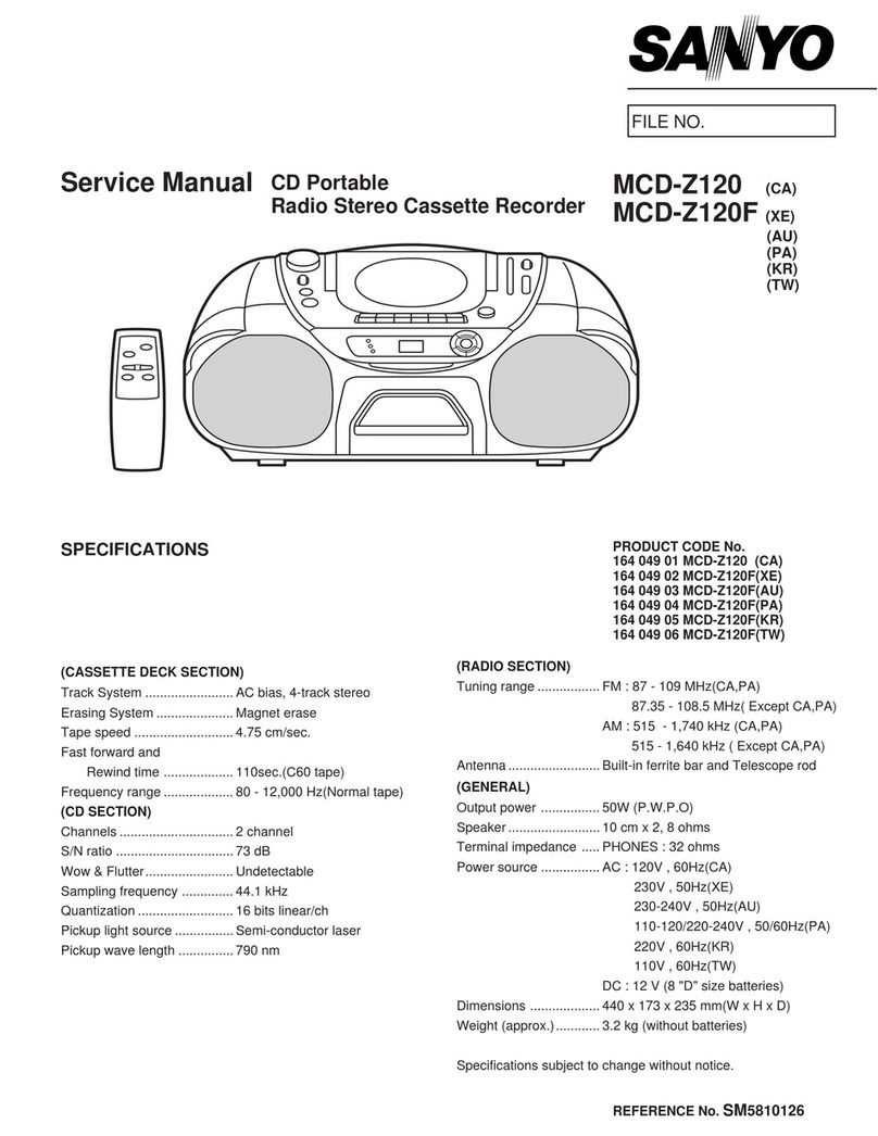
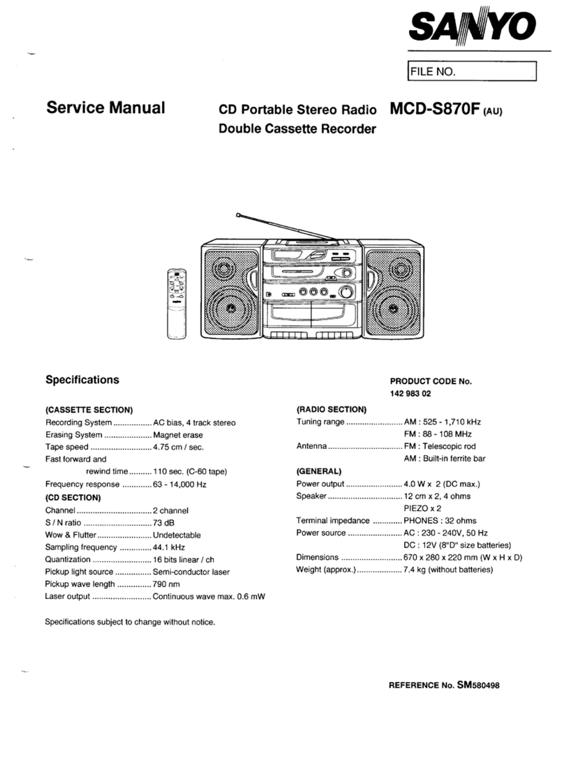
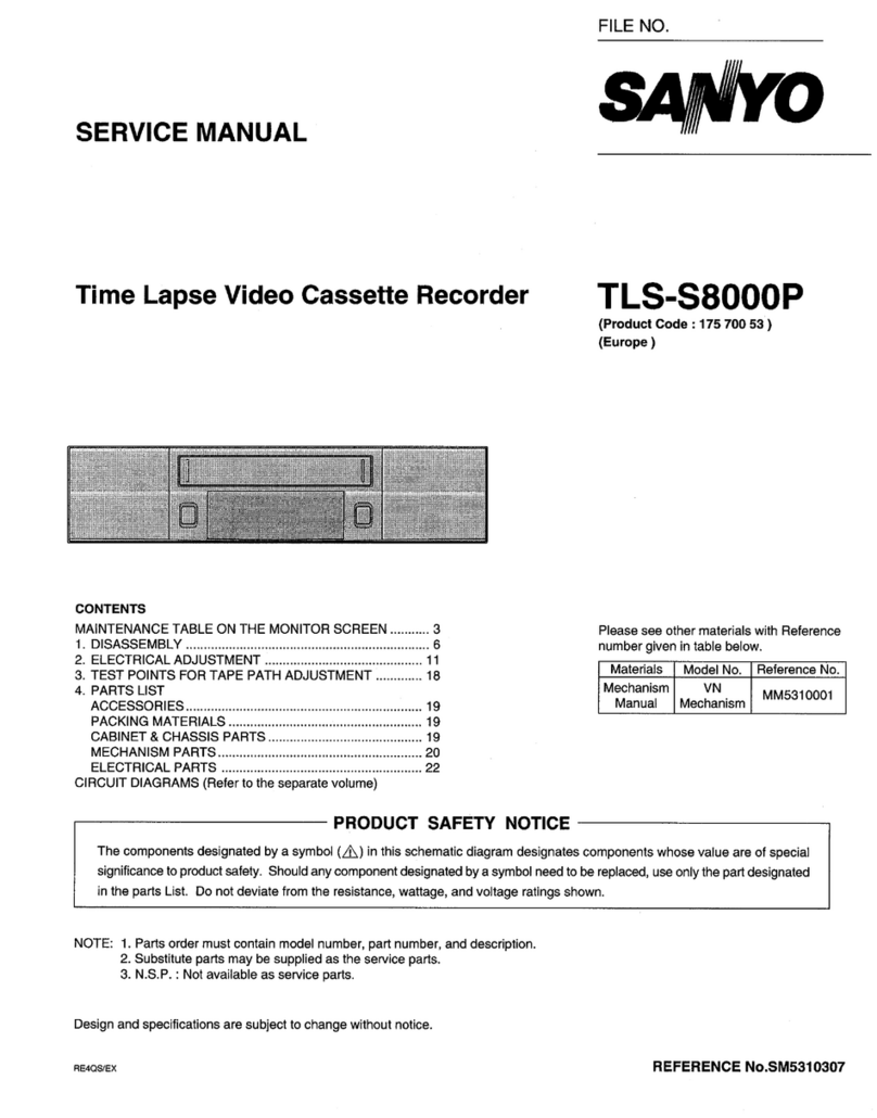
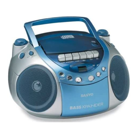
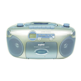
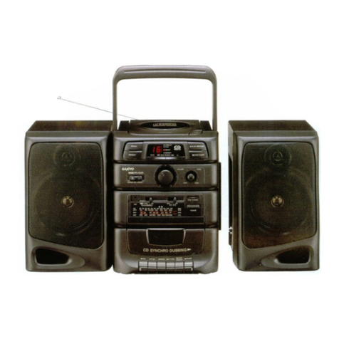
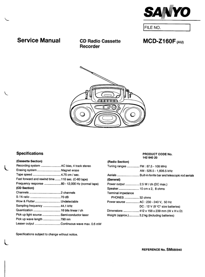
Sanyo M7770K User manual

MINI
STEREO
CASSETTE
RECORDER
ee
eae
SoAN
YO
Power
Source
Ee
ee
a
as
9
({UM-2:
HP11,
¢
Cell,
Babyzelle,
R14)
x
6
Output:
Power
2
2
oe
eee:
3.5W
x
2
(Max.)
Power
GonsumplOn
vee
eee
es
OW
Current
Consumption
(at
Vol.
Min.)
Record
mode...
oe
eee.
265mA
Playback
mod6
..
oye
ee
175mA
Fast
Forward
mode.
2
vec
155mA
Rewind
mode
csc.
sk
e.
165mA
Recording
System.
se
AG
Blas
Erasing
SYStOM
oc
lise
eh
ee
ge
AC
Erasing
ape
Sheed
2
ee
1-7/8
10s.
£3%
Wow
&
Flotiere
ie
eee
0.15%
WRMS
Fast:
Forward
Time:
22
eee.
110sec.
(with
C-60)
Rewtnd:
Pime:oisoee
ieee
ie
110sec.
(with
C-60)
Frequency
Response
(Overall)
PO2
O39
solo
ee
AQHz
~
13,000
Hz
CHO2
ee.
40Hz
~
14,000
Hz
Metab:
oe
es
AOHz
~
16,000
Hz
Erase
Ratio
(Overall,
with
Fe203).
.
Crosstalk
(with
Fe203)
TACK
AO
VEC
este
hee
aoe
:
Hume&:Notse
(at
Volo
Mins)
oc
oe.
Input
Sensitivity
and
Impedance
MIC,
Ee
ec
Se
NN
eee
Output
Level
and
|mpedance
PEN
UE
ee
a
EXT
SDeaker
1)
ou
en
Headphone
eve
ee
ik
ee
;
Frequency
Range
MW
a
Ser
i
ae
Se
a, Se
ce
ed
ee
a
a
a
ch
i
se ee
J
a
ee
a
a,
Se
ee
ce
eo
—Specifications
subject
to
change
without
notice.—
142
340
24
|
.
60dB
Signal
to
Noise
Ratio
(with
Fe203)
..
48dB
50dB
—60dBs
0.3mV/3.3ki2
100mV/100k22
300
mV/2.2
kad
2~
3202
32
82
525
~
1
,605kHz
2.3~7.3MHzZ
AS
~
2ZBMAZ
88
~
108MHz
WM-3000

DISASSEMBLY
INSTRUCTIONS
GENERAL
REMARKS
Before
disassemblying
the
unit,
spread
a
soft
cloth
or
a
rubber
mat
on
the
work
bench
to
avoid
scratches
and
grease
stains.
Do
not
spread
anything
which
is
likely
to
cause
static
electricity
because
transistors
and
|Cs
are
easily
broken
by
it.
Correctly
reassemble
the
unit,
noting
the
kinds
of
fastening
screws
and
the
lead
arrangement.
Please
refer
to
‘’Schematic
Diagrams”
and
‘‘Exploded Views”.
CABINET
BOTTOM
ASSEMBLY
REMOVAL
1.
Take
out
the
cassette
tape
from
the
compartment
by
pressing
the
STOP/EJECT
button.
Remove
the
battery
compartment
lid
and
take
out
the
six
batteries
from
the
compartment.
Then,
remove
the
seven
screws
(1
—
7)
fastening
the
Cabinet
Bottom.
Pull
out
the
connector
of
the
antenna
from
the
Radio
Tuner
P.C.Board.
Then,
remove
the
Cabinet
Bottom
by
lifting
it
in
the
direction
of
the
arrow.
Cabinet
Bottom
4.
Reassemble
in
reverse
order.
RADIO
CHASSIS
ASSEMBLY
REMOVAL
1.
After
removing
the
Cabinet
Bottom,
pull
out
the
volume
control,
tone
control,
balance
control,
and
tuning
knobs
from
the
unit.
Balance
Control
Knob
Volume
Control
Knob
Tuning
Knob
8
Tone
Control
Knob
Connector
(TP6)
Connector
(CN5)
2.
Pull
out
Connector
CN5
from
the
Amplifier
P.C.Board
and
then,
Connector
TP6
from
the
Radio
Tuner
P.C.Board.
3.
Remove
the
screw
(8)
fastening
the
Radio
Chassis.
4.
Remove
the
Radio
Chassis
by
lifting
it
in
the
direction
of
the
arrow.
Radio
Chassis
5.
Reassemble
in
reverse
order.
a
ae

DISASSEMBLY
INSTRUCTIONS
(Continued)
AMPLIFIER
P.C.BOARD
ASSEMBLY
REMOVAL
RADIO
TUNER
P.C.BOARD
REMOVAL
1.
Follow
the
instructions
for
the
Cabinet
Bottom
Assembly
1.
Follow
the
instructions
for
the
Radio
Chassis
Assembly
Removal.
Removal.
2.
Pull
out
Connector
CN3
from
the
P.C.Board
and
remove
2.
Turn
the
Tuning
Knob
fully
in
an
arbitrary
direction.
the
leads
from
the
Volume
P.C.Board.
3.
Remove
the
screws
(10
and
11)
fastening
the
Radio
Tuner
P.C.Board.
Then,
detach
the
P.C.Board
by
lifting
it
in
the
direction
of
the
arrow.
Radio
Tuner
P.C.B.
Radio
Chassis
.
4.
Reassemble
in
reverse
order.
Amplifier
P.C.B.
NOTE:
Do
not
turn
the
Tuning
Knob
before
the
Radio
Tuner
P.C.Board
is
re-mounted
to
the
unit.
When
the
Radio
Tuner
P.C.Board
is
mounted,
insert
the
shaft
of
the
variable
capacitor
into
the
hole
on
the
drum.
After
that,
check
to
see
that
correct
dial
indications
are
obtained.
3.
Carefully
remove
the
P.C.Board
by
lifting
it
in
the
numerical
MECHANISM
CHASSIS
REMOVAL
order
as
illustrated.
1.
Remove
the
Radio
Chassis
from
the
unit
by
following
its
removal
instruction
and
then,
a
screw
(9)
fastening
the
Amplifier
P.C.Board.
Amplifier
P.C.B.
2.
Remove
the
two
screws
(12
and
13)
fastening
the
AMSS
Program
P.C.Board
and
then,
the
P.C.Board.
3.
Remove
the
four
screws
(14
—
17)
fastening
the
Chassis
and
the
two
screws
(Red
and
Black)
running
from
the
motor.
4.
Remove
the
Mechanism
Chassis
by
lifting
it
in
the
direction
of
the
arrow.
Note
the
lead
connections.
4.
Reassemble
in
reverse
order.
5.
Reassemble
in
reverse
order.

DISASSEMBLY
INSTRUCTIONS
(continuea)
CASSETTE
COMPARTMENT
LID
REMOVAL
sem
C
:
-
1,
Open
the
cassette
compartment
lid
by
pressing
the
Mechanism
Chassis
STOP/EJECT
button.
2.
Unlock
the
compartment
latches
from
the
Cabinet
Top
by
pushing
the
both
sides
of
the
compartment
lid
strong.
Then,
the
lid
will
be
easily
removed
from
the
unit.
Leads
(Red
and
Black)
Mechanism
Chassis
Cassette
Compartment
Lid
3.
Reassemble
in
reverse
order.
NOTICE
ON
REASSEMBLY
1.
Refer
to
‘Wiring
Diagram”’
for
re-wiring.
2.
Refer
to
‘Exploded
Views”’
for
lead
arrangement.
3.
Check
to
see
that
the
lead
wires
or
electrical
components
do
not
touch
the
driving
mechanism.

ADJUSTMENTS
GENERAL
REMARKS
@
Before
adjustment,
wipe
the
tape
contacting
surfaces
clean
as
well
as
the
contacting
surfaces
of
the
driving
parts
with
a
soft
cloth
soaked
in
alcohol.
Trouble
may
occur
because
of
oil
and
grease
stains.
@
Carefully
handle
the
belt
because
grease
easily
attaches
to
it.
@
Check
the
rubber-used
parts.
If
the
rubber
has
quality
deterioration
or
scratch
marks,
replace
the
part
with
a
new
one,
Unless
especially
specified,
set
the
unit
and
measuring
instruments
as
follows:
@
Tape
Select
Switch............
0202
eae
NORMAL
@
Function
SWItth
«
664.454.0404
555.456.549.484
4
TAPE
@:
Mode:
SWitthwes
se
eS
oe
ee
lw
ee
Ree
STEREO
@
Beat
Cancel
Switch
.........
0.0
eee
ee ee
ee
3
@
Balance
Control..............
Center
(click
position)
©.
“Tone
CoOntrGl:
«405-3
4.2.2.6
hw
ee
ee
we
a
High
©:
Nolime
Control’
<s-004
Ss
yee
ke
ee
Ne
eee
ows
Arbitrary
@®
DC
Constant-Voltage
Regulator
Output
.......
9.0V
DC
NOTE:
1.
Perform
each
adjustment
in
the
described
order.
2.
Obtain
the
output
from
the
line
output
terminal.
3.
Supply
9.0V
DC
from
the
constant-voltage
regulator
to
the
unit.
EQUIPMENT
REQUIRED
@
VTVM
(2
sets)
Frequency
Counter
Dummy
Load
(47
k-ohm)
Dualtrace
Synchroscope
Test
Tapes
*
3kHz
Test
Tape
(Example:
TEAC
MTT-111)
for
Tape
Speed
Adjustment
*
8kHz
Test
Tape
(Example:
TEAC
MTT-113C)
for
Head
Azimuth
Adjustment
@
DC
Constant-Voltage
Regulator
@
Alignment
Tool
AMSS
SOLENOID
ADJUSTMENT
AMSS
(Automatic
Music
Select
System)
detects
a
silent
space
(unrecorded
portion)
between
each
music
on
a
music
tape
and
automatically
plays
back
a
desired
music
from
the
start.
NOTE:
Unrecorded
portion
should
last
more
than
approximately
four
seconds.
It
may
not
operate
correctly
in
the
following
cases:
*
When
the
recorded
sound
is
often
interrupted
as
in
a
speech
tape.
When
the
silent
space
does
not
last
long
enough
(less
than
four
seconds).
When
there
is
an
appreciable
noise
in
the
silent
space
between
two
adjacent
programs.
When
the
unit
is
placed
on
a
television
set,
AMSS
may
not
Operate
correctly
due
to
adverse
effect
of
the
TV
signal.
In
this
case,
put
the
unit
away
from
the
television
set.
*
If
AMSS
Solenoid
is
not
correctly
positioned,
AMSS
mechanism
does
not
function
correctly,
F.FWD
or
Rewind
button
is
released
while
Automatic
Music
Select
System
is
working,
or
a
button
may
not
be
locked.
In
this
case,
perform
the
adjustment
as
follows:
1.
Remove
the
Chassis
from
the
unit
by
following
its
removal
instructions.
2.
Loosen
the
two
screws
fastening
the
Spacer
of
the
Solenoid.
Then,
adjust
the
Spacer
by
moving
it
in
the
direction
of
the
arrow,
so
that
the
Lock
Plate
is
tightly
attached
to
the
two
absorption
surfaces
as
illustrated.
Spacer
Screw
(ime
wae
seme
ee)
ae
No
Clearance
3.
After
the
adjustment,
tighten
the
screws
fastening
the
Spacer.
Set
the
unit
in
the
playback
mode
and
check
that
AMSS
mechanism
functions
correctly
as
follows:
*
Check
if
F.FWD
button
can
be
locked
by
pressing
it.
*
Check
if
Rewind
button
can
be
locked
by
pressing
it.
4.
Readjust
the
spacer
position
if
either
F.FWD
or
Rewind
button
cannot
be
locked
or
is
soon
released.
5.
After
the
confirmation,
secure
the
screws
fastening
the
Spacer
with
paint
or
glue.
—

ADJUSTMENTS
(Continued)
TAPE
SPEED
ADJUSTMENT
1.
Remove
the
cassette
compartment
lid
and
connect
a
frequency
counter
to
the
left
or
right
channel
LINE
OUT
as
illustrated.
Then,
play
back
a
3kHz
test
tape
(Example:
TEAC
MTT-111).
Frequency
Counter
3000
Hz
(+3
%)
Dummy
Load
47k
ohm
LINE
OUT
2.
Adjust
the
tape
speed
by
turning
the
potentiometer
inside
the
Motor
with
an
alignment
tool
until
the
frequency
counter
reads
3kHz
(+10Hz).
Tape
Speed
Adjustment
HEAD
AZIMUTH
ADJUSTMENT
1.
Remove
the
cassette
compartment
lid
and
connect
a
VIVM
and
a
dualtrace
synchroscope
to
both
channels
LINE
OUT
as
illustrated.
Set
the
synchroscope
as
follows:
PV
OES
tis
og:
i
astas
Oy
Se
ae
ene
SO
te
eee
oe
CHOP
PP
«OIA
ACESS
1k
Fak
he
tlhe
Sata
See
hho
in
INT.
(CH1
or
CH2)
7
SVWVGER
MODE.
fgscicewtee
dot
eras
AUTO
(automatic)
-
Azimuth
Adjusting
Screw
Synchroscope
Dummy
Load
47k
ohm
LINE
OUT
©
©
Oy
Dummy
Load
47k
ohm
Insert
a
8kHz
test
tape
(Example:
TEAC
MTT-113C)
into
the
cassette
compartment
and
play
it
back.
_
Slowly
turn
the
azimuth
adjusting
screw
until
the
amplitudes
of
both
channel
signal
wave
forms
are
at
maximum
and
both
wave
forms
overlap.
Set
to
optimum
at
maximum
reading
of
the
VIVM.
Adjustment
R/P
Head
|
yumeanannees
ateaeaneanillAninnan
ne
AIRMAN
SAAN
PANELED
SIR
AE
POORER
CHAO
LE
SOAPS
SEAL
SIAL
4.
After
the
adjustment,
secure
the
azimuth
adjusting
screw
with
paint
or
glue.

TUNER
ADJUSTMENT
Measuring
Instruments
Required
AM
Signal
Generator
FM
Standard
Signal
Generator
Generator
Scope
Stereo
Signal
Generator
Loop
Antenna
Dummy
Antenna
(75
ohm,
unbalanced
type)
VTVM
:
Frequency
Counter
Distortion
Meter
Oscilloscope
Dummy
Load
(3.2
ohm)
Alignment
Tool
NOTE:
Use
an
alignment
tool
with
plastic
grip
for
all
adjustments.
MW
ALIGNMENT
Standard
test
frequency
400
Hz
and
modulation
30%
at
AM
Alignment
of
Signal
INPUT
OUTPUT
Generator
455kHz
Low
End
T3,
T4
and
T5
Tuning
Dial
Setting
Adjustments
Remarks
Obtain
symmetrical
curve
and
maximum
amplitude.
Connect
standard
loop
antenna
to
output
terminal
of
gene-scope.,
Connect
input
terminal
of
gene-
scope
to
detector
Calibration
of
IF
for
AM
Place
bar
antenna
output.
60
cm
away
from
(CN1-2
and
CN1-1
loop
antenna.
or
CN1-3)
Obtain
sine-wave
of
400Hz
and
maximum
amplitude.
Connect
standard
loop
antenna
to
output
of
AM
signal
generator.
Calibration
of
Tuning
Range
Connect
VT
VM
with
3.20hm
dummy
load
and
oscilloscope
to
Adjustment
Place
bar
antenna
Phones/Ext.
Speaker
600
kHz
600kHz
|
L4
(bar
ant.
coil)
of
60
cm
away
from
terminal.
Tracking
loop
antenna.
1,400
kHz
1
400
kHz
Repeat
the
above
steps
until
no
further
change
is
noted
in
any
of
the
adjustment.
SW1
ALIGNMENT
Obtain
sine-wave
of
400Hz
and
maximum
amplitude.
Connect
standard
Joop
antenna
to
output
of
AM
signal
Calibration
of
Tuning
Range
Alignment
:
of
Signal
Tuning
Dial
INPUT
OUTPUT
Generator
7.5MHz
High
End
TC4
Connect
VT
VM
with
3.20hm
dummy
load
generator.
and
oscilloscope
to
Adjustment
|
Place
bar
antenna
Phones/Ext.
Speaker
2.5MHz
2.5MHz
|
L4-3
(bar
ant.
coil)
of
60cm
away
from
terminal.
Tracking
6.5MHz
6.5MHz
TC3
(PVC)
Repeat
the
above
steps
until
no
further
change
is
noted
in
any
of
the
adjustment.
loop
antenna.

Frequency
TUNER
ADJUSTMENT
(Continued)
SW2
ALIGNMENT
Alignment
Adjustments
Remarks
INPUT
OUTPUT
Generator
Calibration
|
Connect
AM
signal
oo
Ed
Obtain
sine-wave
of
400
Hz
of
generator
to
antenna
|
Connect
VTVM
with
and
maximum
amplitude.
a
ae
Range
|
terminals
(TP1
or
3.20hm
dummy
load
TP2)
and
oscilloscope
to
Adjustment
|
through
dummy
Phones/Ext.
Speaker
es
[
ane
[oe
of
antenna
terminal.
Tracking
(300hm/10
pF).
Repeat
the
above
steps
until
no
further
change
is
noted
in
any
of
the
adjustment.
Tuning
Dial
Setting
FM
ALIGNMENT
Standard
test
frequency
400Hz
and
deviation
22.5kHz
Tuning
Dial
;
Obtain
symmetrical
curve
and
maximum
amplitude.
Turn
T2
(blue
core)
Connect
output
Connect
input
fully
counter-
terminal
of
gene-
terminal
of
gene-
clockwise.
scope
to
pin
3
of
scope
to
detector
T1
Nd
Calibration
1C1
through
output.
;
capacitor
(10
pF)
(CN1-2
and
CN1-1
10.7
MHz
Low
End
or
CN1-3)
Obtain
S
curve
and
maximum
amplitude.
T2
(blue core)
Alignment
of
Signal
INPUT
OUTPUT
Generator
Calibration
Connect
FM
signal
|
87.2MHz
2MHz
a
a
Obtain
sine-curve
and
of
generator
toantenna
|
Connect
VT
VM
with
maximum
amplitude.
Tuning
Range}
terminals
(TP1
and
3.20hm
dummy
load
TP2)
through
and
oscilloscope
to
Adjustment
|
dummy
antenna.
Phones/Ext.
Speaker
of
(750hm,
unbalanced
|
terminal.
Repeat
the
above
steps
until
no
further
change
is
noted
in
any
of
the
adjustment.
FM
MULTIPLEX
ADJUSTMENT
|
38kHz
(V.C.0.)
ADJUSTMENT
1.
Connect
the
frequency
counter
to
the
sixteenth
pin
(TP7)
in
Prior
to
the
adjustment,
set
the
unit
as
follows:
|C3
and
a
resistor
(330
k-ohm)
as
illustrated.
@
Function
Switch
...............
0005
RADIO
(ON)
@
Band
Select
Switch
...........
0.00.
FM
2.
Adjust
the
potentiometer
(P1)
until
the
oscillation
frequency
@
Mode
Switch.............00
0c
eee
eee
STEREO
of
IC3
becomes
38kHz
(+20Hz).
@
Balance
Control..............
Center
(click
position)
©
TOne
CON:
6a45no
sn
Gee
ea
Maximum
@
Volume
Control
.........
0...
cee
ee
eee
ns
Center

DIAL
CORD
STRINGING
1.
Mount
the
Radio
Tuner
P.C.Board
on
the
Radio
Chassis
and
4.
Hook
the
dial
cord
to
the
spring
and
tie
the
cord
where
the
then,
the
Drum
to
the
shaft
of
the
variable
capacitor.
spring
tip
extends
until
the
spring length
becomes
approximately
31mm.
2.
Tie
the
dial
cord
of
length
1,070mm
(effective
length:
950mm)
and
diameter
$5
to
the
spring
and
hook
the
spring
5.
Secure
the
place
where
the
spring
is
hooked
to
the
drum
and
to
the
illustrated
position
of
the
drum.
the
knot
in
the
dial
cord
with
paint
or
glue.
3.
Engage
the
dial
cord
as
illustrated
in
the
following
order.
6.
Turn
the
Tuning
Shaft
counterclockwise
until
it
stops
and
Drum
==
Pulley
A
==
Pulley
B
==>
Pulley
C
==>
Tuning
set
the
left
edge
of
the
pointer
to
the
mark
on
the
Radio
Shaft
(3
turns)
==>
Pulley
D
=>
Drum
==>
Spring
Chassis
as
illustrated.
Then,
fix
the
pointer
there.
7.
Apply
white
lacquer
to
the
pointer
to
secure.
S
Pointer
init
‘
\
Dial
Cord
Roller
B
Soc
SS
ee
Tuning
Shaft
3
Turns
Radio
Chassis
Pointer
Scratch
Mark
about
31mm

Ref.
No.
CN3
CNS
CA1-
CAI
CA2
CA3
CA4
CAS
CA5
CA6
CA7
CA8
CA9
CA10
CA11
CA12
CA13
CA14
CA15
CA16
CA17
CA18
CA18
CA19
CA20
CA21
CA21
CA22
CA22
CA23
CA24
CA25
CA26
CX1
CX2
CX3
CX4
CX4
Part
No.
PACKAGE
141
141
141
141
141
141
141
141
141
141
ACCESSORIES
141
141
2
1719
20300
6
1419
65001
6
1419
65004
6
1449
82300
6
1449
82400
6
2519
10021
6
2519
15290
6
2519
23033
6
3119
19300
6
4559
00100
4
1919
71480
4
2369
72251
4
2419
72492
6
4729
01900
6
4729
32400
142
6
4119
31632
CABINET
141
141
141
141
141
141
141
141
141
141
141
141
141
141
141
141
141
141
141
141
141
141
141
14]
141
141
141
141
141
4
2359
70990
4
2359
75727
4
2359
75758
0
1249
23201
0
1249
23204
2
8529
06200
2
1639
44300
2
1639
44200
0
1119
88801
0
1119
88804
2
4469
36500
2
1519
24700
2
1659
09300
2
1639
51100
2
1639
51000
2
4469
31700
2
1149
29200
4
1519
71084
2
2719
18500
Q
5519
08500
2
1659
09400
2
7419
77200
0
1719
10400
0
1719
10403
2
1149
29201
2
3729
00801
0
1339
09703
0
1339
09706
2
1119
84801
2
1119
84804
2
4219
09800
2
1649
12900
4
2449
70330
2
4729
03001
102
3
1303
01011
102
3
1302
60811
143
3
1303
03018
101
101
3
1302
60614
3
1302
60618
PARTS
LIST
Description
Handle
Individual
Carton
(White)
Individual
Carton
(Blue)
Styrofoam
Case,
Left
Styrofoam
Case,
Right
Poly
Cover
100
x
210
Poly
Cover
Poly
Cover
230
x
330
Reinforce
Handle
Serial
No.
Sheet
AC
Adaptor
Adaptor
Plug
Assy
Cassette
Caution
Label
POP
Label
Instruction
Manual
RT
Pin
Socket
Connector
4P
Assy
-
Connector
3P
Assy
Cassette
Lid
Assy
(White)
Cassette
Lid
Assy
(Blue)
Spring,
Cassette
Lid
Fine
Tuning
Knob
Tuning
Knob
Cabinet
Top
Completed
(Speaker
(3002)
[SP102
&
SP202]
is
Included
)
(White)
Cabinet
Top
Completed
(Speaker
(3000)
[SP102
&
SP202]
is
Included
)
(Blue)
Cushion
Reflector
AMSS
Button
Volume
Knob
Tone
Knob
Cushion,
Mike
Screen,
Speaker
(Right)
Speaker
(3.20) [SP101
&
SP201]
Handle
Holder
Eject
Gear
Assy
Rec.
Mute
Knob
Cassette
Lid
Lock
Handle
Assy
(White)
Handle
Assy
(Blue)
Screen,
Speaker
(Left)
Fix
Speaker
Bracket
Battery
Lid
Assy
(White)
Battery
Lid
Assy
(Blue)
Cabinet
Bottom
(White)
Cabinet
Bottom
(Blue)
Screw
Band
Select
Knob
Antenna
Rod
Lug
Screw,
Pan
Hd.
Tapping-1
Screw,
Pan
Hd.
Tapping-1
Screw,
Pan
Hd.
Tapping-B
Screw,
Pan
Hd.
(White)
Screw,
Pan
Hd.
(Blue)
+M3.0x10
+M2.6x8
+M3.0x30
+M2.6x6
+M2.6x6
Q’ty
iar
Part
No.
Description
Q’ty
RADIO
CHASSIS
1
DC1
141
2
8119
09701
Counter
1
4
DC2
141
2
5649
11700
Counter
Belt
1
1
DC3.
141
2
8139
09500
Counter
Bracket
1
1
DC4
141
2
8519
29400
Spring,
Stop
Lever
1
1
DC5
141
2
3519
57700
Bracket
Eject
Arm
1
1
DC6
141
2
4729
04000
Lug
1
1
DC7
141
2
2449
45400
Sheet
1
1
DC8
4
1329
78400
AMSS
Program
P.C.B.
Assy
[See
PCB3]
1
1
DC9
141
2
8519
78000
Spring,
Stop
1
2
DC10
141
2
5389
03400
Drum
1
DC11
4
2249
70300
‘Fine
Tuner
([FT1]
1
DC12
4
1329
78420
Jack
P.C.B.
Assy
[See
PCB6]
1
DC13.
141
2
3679
31501
Jack
Plate
(White)
1
1
DC1i3.
141
2
3679
31506
Jack
Plate
(Blue)
1
1
DC14
4
1539
70661
Microphone
[BM1
&
BM2]
2
1
DC15
141
2
4219
14000
Screw
4
1
DCi6
141
2
5519
03300
_Dial
Roller
A
3
1
DC17
=
141
2
3119
18100
Radio
Chassis
1
1
DC18
141
2
1449
52900
Dial
Plate
(White)
1
DC18
141
2
1449
52902
Dial
Plate
(Blue)
1
DC19
141
2
8259
04700
_
Dial
Roller
1
DC20
4
1329
78530
VolumeP.C.B.
Assy
[See
PCB5]
1
2
DC21
141
2
3829
18000
Spring,
Terminal
1
1
DC22.
141
2
5119
08100
‘Pointer
1
1
DC23
4
1329
78410
LED
Indicator
P.C.B.
Assy
[See
PCB4]
1
1
DC24
141
2
3829
06700
_—‘
Terminal
Battery
Anode
1
1
DC25
141
2
3829
20800
Spring,
Battery
1
1
DC26
4
1259
71870
Radio
Tuner
P.C.B.
Assy
[See
PCB2]
1
1
DC27
4
1329
78391
Amplifier
P.C.B.
Assy
[See
PCB1]
1
1
DC28
141
2
4469
42500
Cushion,
Screen
Switch
1
1
DC29.
141
2
2449
45100
Screen
Switch
1
DC30
141
2
1629
06800
Function
Knob
3
|
DY1
102
3
1302
61411
Screw,
Pan
Hd.
Tapping-1
+M2.6x14
3
DY2
101
3
1302
00311
Screw,
Pan
Hd.
+M2.0x3
1
DY3
102
3
1302
60811
Screw,
Pan
Hd.
Tapping-1
+M2.6x8
5
DY4
102
3
1302
60818
Screw,
Pan
Hd.
Tapping-1
+M2.6x8
2
DY5
102
3
1302
61011
Screw,
Pan
Hd.
Tapping-1
+M2.6x10
3
DY6
102
3
1703
00811
Screw,
Bind
Hd.
Tapping-1
+M3.0x8
1
NOTES:
1.
Parts
order
must
contain
Model
Number,
Part
Number
and
Description.
2.
Ordering
quantity
of
screws
and
resistors
must
be
multiple
of
10
pcs.
—10—

CABINET
EXPLODED
VIEW

RADIO
CHASSIS
EXPLODED
VIEW
=19—

MECHANISM
PARTS
LIST
so
Part
No.
Description
arty
|
fief.
Part
No.
Description
oy
MECHANISM
MC64
141
2
8529
05400
Spring,
Rod
1
MCi1
=
141
0
3119
19902
Chassis
Assy
1
MC65
141
2
8529
05401
Spring,
Pause
Rod
1
MC2
141
2
8549
10700
Spring,
Slide
Base
1
MC66
141
2
8529
05600
Spring,
Record
Stopper
1
MC3
141
2
8519
97300
Spring,
Interlock
1
MC67
141
2
7419
75800
Pause
Lock
Lever
1
MC4
141
2
8419
10400
Interlock
Lever
|
MC68
141
2
8529
05700
Spring,
Pause
Lock
1
MCS
141
2
8529
07300
Spring,
Idler
Arm
1
MC69
141
2
4539
15800
Washer
2
MC6
141
2
7419
74900
Cassette-up
Lever
1
MC70
141
2
5519
36600
Capstan
Gear
1
MC7
=
141:
2:
8549
08700
=
Spring,
Brake
1
MC71
=141
2
8519
98200
Spring,
Flywheel
1
MC8
141
2
7149
05200
Brake
Arm
1
MC72
141
0
5219
07201
‘Flywheel
Assy
1
MC9
141
2
4459
25200
Brake
Cover
2
MC73
141
2
5649
20900
_Capstan
Belt
1
MC10
141
2
7319
43202
Slide
Base
|
MC74
141
0
3519
20100
Flywheel
Support
Assy
1
MC11
4
2319
72121
Leaf
Switch
(Power)
[S11]
1
MC75
141
2
8529
07200
Spring,
Ground
1
MC12
141
2
7419
68800
Sensor
Lever
1
MC76
141
2
4729
00200
Lug
1
MC13
141
2
3529
29400
Spacer,
Head
1
MC77
4
2649
70344
Solenoid
[SL1]
1
MCi4
141
2
8519
47400
Spring,
Head
1
MC78
141
2
3769
12100
Spacer
Solenoid
1
MC15
4
2429
72190
R/P
Head
[HD1]
1
MC79
4
2319
74990
Leaf
Switch
(AMSS
Switch
B)
[S10]
1
MC16
141
2
4729
01900
Lug
1
MC80
4
2319
72570
Leaf
Switch
(AMSS
Switch
A)
[S9]
1
><¢MC17
4
2429
72200
Erase
Head
[HD2]
1
MC81
141
2
4539
12100
Washer
Spindle
2
MC18
141
2.5519
36400
F.FWD
Gear
1
MC82
141
2
5519
36701
Idler
Pulley
Gear
1
MC19
141
2
4539
09400
Washer
3
MC83
141
0
7439
10400
Idler
Arm
Assy
1
MC20
141
2
8559
01800
Spring,
Supply
1
MC84
141
2
8259
09100
_
Roller
1
MC21
141
0
5319
05400
Supply
Reel
Assy
1
MZ1
=
112
3:
1304
00082
—_E
Ring
M4.0
|
MC22
141
2
4539
15700
Washer
2
MZ2
103
3
1302
00811
Screw,
Pan
Hd.
Tapping-2
“+M2.0x8
3
MC23
141
0
5319
05301
Take-up
Reel
Assy
1
MZ3
=
101
3
1702
00611
Screw,
Bind
Hd.
+M2.0x6
1
MC24
141
2
8539
45200
Spring,
Cassette
1
MZ4
101
3
2502
00611
Screw,
Cylinder
Hd.
-M2.0x6
1
MC25
141
2
8539
41102
Spring,
Cassette
1
MZ5
~=101
3
1702
00811
Screw,
Bind
Hd.
+M2.0x8
2
MC26
141
2
8519
96901
Spring,
Cassette-up
1
MZ6
143
3
1702
60811
Screw,
Bind
Hd.
Tapping-B
+M2.6x8
4
MC27
+141
0
5419
03200
‘Pinch
Roller
Assy
1
MZ7
=:
112
3
1302
00082
Ring
M2.0
1
MC28
141
2
8519
97200
Spring,
Pinch
Roller
1
MZ8
102
3
1302
60811
Screw,
Pan
Hd.
Tapping-1
+M2.6x8
1
MC29
141
2
4219
13201
Screw
w/Washer
1
MZ9
=
101
3
1302
60811
Screw,
Pan
Hd.
+M2.6x8
3
MC30
141
0
7319
24201
—
Eject
Plate
Assy
1
MZi0
112
3
1706
30040
Grip
Ring
M6.3
|
MC31
141
2
8519
38700
Spring,
Head
Lever
1
MZ11
102
3
1302
00611
Screw,
Pan
Hd.
Tapping-1
+M2.0x6
1
MC32
4
5279
71173
Motor
[M1]
1
MZi2
112
3
1301
20082
ERing
M1.2
1
MC33
141
2
3789
08700
Bracket,
Motor
1
MZ13
101
3
1302
00811
Screw,
Pan
Hd.
+M2.0x8
1
MC34
141
2
4459
11800
Cushion,
Motor
3
MZi4
101
3
1302
00411
Screw,
Pan
Hd.
+M2.0x4
1
MC35
141
2
3529
19900
Spacer,
Motor
3
MZ15
101
3.1702
00411
Screw,
Bind
Hd.
+M2.0x4
1
MC36
141
2
8429
16100
Record
Switch
Lever
1
MC37
141
2
8519
78000
Spring,
Stop
1
NOTES:
MC38
141
2
4539
17200
Washer
|
1.
Parts
order
must
contain
Model
Number,
Part
Number
and
Description.
MC39
141
2
7319
49300
_Lock
Plate
{
2.
Ordering
quantity
of
screws
and
resistors
must
be
multiple
of
10
pcs.
MC40
141
2.5519
36500
Take-up
Gear
1
MC41
141
0
7439
09200
Take-up
Arm
Assy
1
MC42
141
2
8519
33000
Spring,
Index
Lock
Lever
1
MC43
141
27419
75500
Shut-off
Lever
1
MC44
=141
2
7439
26200
Record
Stopper
Lever
1
MC45
141
2
1619
91300
Record
Button
1
MC46
141
27319
50000
Record
Rod
1
MC47
=
141
2
1619
91200
Play
Button
1
MC48
§=141
2
7319
49900
Play
Rod
1
MC49
141
2
1619
91100
Select
Button
3
MCS0
141
2
7319
49800
Rewind
Rod
1
MCS1
141
2
7319
49700
F.FWD
Rod
1
MC52
141
0
7319
25200
Pause
Rod
Assy
1
MCS3
141
2
4219
12100
Screw
w/Washer
1
MC54
141
21619
91400
Stop
Button
1
MC55
141
2
7319
49500
Stop
Eject
Rod
1
MC56
141
2
8529
05800
_Lock
Spring,
Lever
1
MC57
141
2
7419
76500
—_Lock
Lever
1
MC58
141
2
7519
55300
Spindle
Lock
Lever
1
MC59
141
23519
57100
_
Bracket
Plate
1
MC60
141
28549
10600
Spring,
Play
Rod
1
MC61
141
28549
10800
Spring,
Sensor
1
MC62
141
28519
25400
Spring,
Click
1
MC63
141
28529
05500
=
Spring,
Rod
1
4,
ii

MECHANISM
EXPLODED
VIEW
b—
mez
cB
mez
—Ne18
|
og
Wa
Mc25
|
M026
“4
MZ4-S
o—MZ3
PSN
|
|
A
Web
Qo
ners
MC14—2
«nS
MC31
=)

MECHANISM
EXPLODED
VIEW
(continued)
o—MZI13
ewer
wzi4a—o
&
NZIS
MC78
MCBS
Us
—
<—w063
|
Ao—
mca
MC62
“Me,
|
MEI
ose
ag
iM

Ref.
No.
PCB1
CN1
CN2
CNS
CNS
S2
$3
$4
SS
$6
J1
J2
J3
J4
J5
L101
L201
L301
L302
L303
D101
D102
D103
D104
D201
D202
D203
D204
D301
D302
D303
Q101
Q201
Q301
Q302
Q303
Q304
Q305
Q306
Q307
Q308
C301
10302
C101
C102
C103
C104
C105
C106
C107
C108
C109
C110
C111
C112
0113
C114
C115
C116
C117
C121
C122
Part
No.
Description
AMPLIFIER
P.C.B.
ASSY
Amplifier
P.C.B.
Assy
Radiator
IC
(for
IC
[302])
4
1329
78391
2
3689
08400
4
2359
75669
4
2369
73380
4
2369
73370
4
2369
73360
4
2319
75700
4
2319
75710
4
2319
75341
4
2319
75341
4
2319
72462
4
2359
71780
4
2359
73470
4
2359
75701
4
2359
75800
4
2359
72954
4
2729
70480
4
2729
70480
4
2539
70301
4
2539
70301
4
2532
00470
4
2029
71440
4
2029
71440
4
2029
71440
4
2029
71440
4
2029
71440
4
2029
71440
4
2029
71440
4
2029
71440
9
2470
13540
4
2029
72210
9
9110
18820
5
5000
53664
5
5000
53664
9
9000
53664
9
4570
73460
9
9000
53654
9
4570
73460
9
5000
53664
9
5000
53664
9
5000
53664
9
5000
53664
4
2069
71710
14
—_h,
202
202
203
203
203
203
203
203
203
203
203
203
206
CD1
0
4500
0002V
CC4
7
2500
KEOOC
CC1
8
1500
JDOOC
CC3
3
2500
KEO0C
CC3
3
1500
KEO0C
CC3
3
1500
KEOOC
CC1
0
2500
KEO0C
CDi
0
7100
0001V
CC1
0
2500
KEO0C
CD1
0
6160
0000V
CD1
0
4500
0002V
CM3
3
3500
KOOSV
CD1
0
5500
0000V
CC4
7
1500
KEOOC
CD1
0
5500
0000V
CC1
0
2500
KEO0C
Cl8
2
3250
KFOOC
CC1
0
2500
KEOOC
CD4
7
6100
0001V
5
1384
19210
Connector
5P
Assy
Connector
5P
Connector
4P
Connector
3P
PC.BOARD
PARTS
LIST
Slide
Switch
(Record/Play)
Push
Switch
(Rec.
Mute)
Lever
Switch
(Tape
Select)
Lever
Switch
(Function)
Lever
Switch
(Mode)
Jack
1P
(Mike,
Left)
1P
Jack
(Mike,
Right)
Jack
5P
With
Switch
(Headphones)
Jack
5P
(Phones/Ext.
Speaker)
Ext.
Power
Socket
Coil
(33mH)
Coil
(33mH)
Micro
Inductor
(100,cH)
Micro
Inductor
(100;H)
Choke
Coil
(470;2H)
Diode,
1SS95
Diode,
1SS95
Diode,
1SS95
Diode,
1S$95
Diode,
1SS95
Diode,
1SS95
Diode,
1SS95
Diode,
1$S95
Diode,
DS135
Diode,
MTZ6.8A
Diode,
1S
188
Transistor,
2SC
536
Transistor,
2SC
536
Transistor,
2SC
536
Transistor,
2SD
734
Transistor,
2SC
536
Transistor,
2SD
734
Transistor,
2SC
536
Transistor,
2SC
536
Transistor,
2SC
536
Transistor,
2SC
536
IC,
M51544L
IC,
LA4192
Electrolytic
0.1
uF
Ceramic
0.0047
uF
Ceramic
180pF
Ceramic
0.0033
uF
Ceramic
330pF
Ceramic
330pF
Ceramic
0.001
uF
Electrolytic
100
uF
Ceramic
0.001
uF
Electrolytic
10uF
Electrolytic
0.1
uF
Mylar
0.033
uF
Electrolytic
1
pF
Ceramic
470pF
Electrolytic
1
uF
Ceramic
0.001
uF
Boundary
0.082uF
Ceramic
0.001
uF
Electrolytic
47
uF
30V
S0V
90V
S0V
S0V
90V
S0V
10V
SOV
16V
S0V
90V
90V
SOV
S0V
SOV
20V
d0V
10V
+10%
+5%
+10%
+10%
+10%
+10%
+10%
+10%
+10%
+10%
+10%
+10%
Q’ty
—16—
ee
Part
No.
Description
Q’ty
C123
CD47
6100
0001V
_
Electrolytic
47pF
10V
1
1
C124
4
2239
70650
Capacitor
2200uF
10V
1
1
C125
CM15
4500
KOOSV
Mylar
0.15uF
50V
+10%
1
1
C126
CC3
3
1500
KEOOC
Ceramic
330pF
50V
+10%
1
1
C127
CC2
2
0500
KDOOC
Ceramic
22pF
50V
+10%
1
1
C128
CC1
81500
KEOO0C
Ceramic
180pF
50V
+10%
1
1
C129
CC2
2
1500
KEOOC
Ceramic
220pF
4
50V
+10%
1
1
C201
CD10
4500
0002V
_
Electrolytic
O1uF
50V
1
1
C202
CC47
2500
KEOO0C
Ceramic
0.0047uF
50V
+10%
1
1
C203.
CC1i
81500
JDOOC
Ceramic
180pF
50V
=+5%
1
1
C204
CC3
3
2500
KEOOC
Ceramic
0.0033uF
50V
+10%
1
1
C205
CC3
31500
KEOO0C
Ceramic
330pF
50V
+10%
1
1
C206
CC3
3
1500
KEOOC
Ceramic
330pF
50V
+10%
1
1
C207
CC1i
0
2500
KEOOC
Ceramic
0.001iunF
50V
+10%
1
1
C208
CD10
7100
0001V
Electrolytic
100uF
10V
1
1
C209
CCi
0
2500
KEOQOC
Ceramic
0.00iuF
50V
+10%
1
1
C210
CD10
6160
0000V
—
Electrolytic
10uF
16V
1
1
C211.
=
CD10
4500
0002V
—
Electrolytic
O1iuF
50V
1
1
C212
CM33
3500
KOOSV
Mylar
0.033uF
50V
+10%
1
1
C213
CD10
5500
0000V
_
Electrolytic
1puF
=
50V
1
1
C214.
CC47
1500
KEOOC
Ceramic
470pF
50V
+10%
1
1
C215
CD10
5500
0000V
__
Electrolytic
1uF
=
50V
1
1
C216
CC10
2500
KEOOC
Ceramic
0.00iuF
50V
+10%
|
1
C217
Cl8
2
3250
KFOOC
Boundary
0.082nF
25V
+10%
1
1
C221
CC10
2500
KEQOC
Ceramic
0.001iuF
50V
+10%
1
1
C222
CD47
6106
0001V
—
Electrolytic
47uF
10V
1
1
C223.
CD47
6100
0001V
Electrolytic
47uF
10V
1
1
C224
4
2239
70650
Capacitor
2200uF
10V
1
1
C225
CM15
4500
KOOSV
Mylar
015uF
50V
+10%
1
1
C226
CC3
3
1500
KEQOC
Ceramic
330pF
50V
+10%
1
1
C227
CC2
2
0500
KDOOC
Ceramic
22pF
50V
+10%
1
1
C228
CCi
8
1500
KEOOC
Ceramic
180pF
50V
+10%
1
1
C229.
CC22
1500
KEOOC
Ceramic
220pF
4=50V
+10%
1
1
C301
CD47
6100
0001V
Electrolytic
47uF
10V
1
1
C302
CD33
5500
0000V
Electrolytic
3.3uF
50V
1
1
C303
CD22
7100
0001V
Electrolytic
220uF
10V
1
1
C304
CD47
4500
0000V
_
Electrolytic
0.47uF
50V
1
1
C305
¢C47
1500
KEOO0C
Ceramic
470pF.
50V
+10%
|
1
C306
CD10
5500
O000V
Electrolytic
1uF
=
50V
|
|
C307
CD22
7100
0001V
—
Electrolytic
220uF
8610V
|
1
C308
CD10
7100
0001V
—
Electrolytic
100uF
10V
1
1
C309
CD10
7160
0001V
—
Electrolytic
100uF
16V
1
1
C310
CD10
8160
0001V
—
Electrolytic
10004F
16V
1
1
C311.
CD47
7100
0001V
—
Electrolytic
470uF
8
10V
1
1
C312
CD22
7100
0001V
—
Electrolytic
220uF
10V
1
1
C313
CD10
7100
0001V
Electrolytic
100uF
10V
1
1
C314
CD10
5500
0000V
Electrolytic
1uF
=
5OV
1
1
C315
CC47
0500
KDOOC
Ceramic
47pF
50V
+10%
1
1
C316
CD22
4500
0002V
Electrolytic
0.22uF
50V
1
1
C317
CD22
4500
0002V
Electrolytic
0.22uF
50V
1
|
C318
CD10
6160
0000V
—
Electrolytic
10uF
16V
1
1
C319
CD10
5500
0000V
Electrolytic
{pF
=
50V
1
1
C320
CD10
6160
0000V
Electrolytic
10uF
16V
1
1
C321
CC2
7
1500
KEOO0C
Ceramic
270pF
50V
+10%
1
1
C322
CM10
3500
KOOSV
Mylar
0.01iuF
50V
+10%
1
1
C323
CP1
0
3101
G@00V
Polypropylen
0.01uF
100V
+2%
1
1
C324
CM10
4500
JOOSV
Mylar
O.1uF
50V
+
5%
1
1
C325
CDi
0
6160
0000V
Electrolytic
10uF
16V
1
1
C326
CD10
6160
0000V
Electrolytic
10uF
16V
1
1
C327.
CC39
1500
KEQ0C
Ceramic
390pF
50V
+10%
1
1
C328
CD33
5500
0000V
Electrolytic
3.3uF
50V
1
1
C332.
CC10
1500
KDOOC
Ceramic
100pF
50V
+10%
1
1
R101
P10
2121
JHOOO
Pretty
Carbon
1kQ
1/8BW
+5%
1
1
R102.
RP4
7
2121
JHOOO
Pretty
Carbon
47kQ
1/8W
+5%
1

PC.BOARD
PARTS
LIST
(continuea)
oe
Part
No.
Description
Q’ty
Abag
Part
No.
Description
Q’ty
R103
RP3
3
2121
JHOOO
Pretty
Carbon
3.3kQ
1/8BW
+5%
1
R301
RP1
01121
JHOOO
Pretty
Carbon
1000
1/8W
+5%
1
R104
RP2
2
2121
JHOOO
Pretty
Carbon
22k)
1/8W
+5%
1
R302
RD1
0
1251
JM000
Carbon
1000
1/4W
=+5%
1
R105
RP10
0121
JHOOO
Pretty
Carbon
100
1/8BW
=+5%
1
R303
RP47
2121
JHOOO
Pretty
Carbon
47kQ
1/BW
+5%
1
R106
RD8
2
3251
JM000
Carbon
82kQ
1/4W
+5%
1
R304
RD1
0
2251
JMO00
Carbon
1kO
=1/4W
+5%
1
R107
RD68
3251
JMO00
Carbon
68kQ
1/4W
+5%
1
R305
RP47
4121
JHOO0
Pretty
Carbon
470kKQ
1/BW
+5%
1
R108
RP7
5
2121
JHOOO
Pretty
Carbon
7.5kQ
1/BW
+5%
1
R306
RP3
3
2121
JHOOO
Pretty
Carbon
3.3kQ
11/8BW
+5%
1
R109
RP27
3121
JHOOO
Pretty
Carbon
27k
1/8W
5%
R307
RPG
8
0121
JHOOO
Pretty
Carbon
680
1/BW
+5%
1
R110
RP2
7
3121
JHOOO
Pretty
Carbon
21kQ
=1/8BW
+5%
1
R308
RP6
8
2121
JHOOO
Pretty
Carbon
6.8kQ
1/8BW
=+5%
1
R111.
=
RP1
5
2121
JHOOO
Pretty
Carbon
1.5kQ
1/BW
+5%
1
R309
RP1
0
2121
JHOOO
Pretty
Carbon
1kQO
=1/8BW
=+5%
1
R112
RP2
2
2121
JHOOO
Pretty
Carbon
2.2kQ
1/BW
+5%
1
R310
RP5
6
A121
JHOOO
Pretty
Carbon
560
1/BW
+5%
1
R113
RP2
2
3121
JHOOO
Pretty
Carbon
22k
1/8BW
+
5%
1
R311.
RP2
2
1121
JHOOO
Pretty
Carbon
2200
1/BW
+5%
1
R114
=RP8
2
2121
JHOOO
Pretty
Carbon
8.2kQ
1/BW
+5%
|
R312
RP1
01121
JHOOO
Pretty
Carbon
1000
1/8BW
+5%
1
R115
RP6
8
4121
JHOOO
Pretty
Carbon
680k-Q
1/8BW
+5%
1
R313
RP2
2
2121
JHOOO
Pretty
Carbon
2.2K
1/8BW
+5%
1
R116
=RP47
2121
JHOOO
Pretty
Carbon
47kQ
1/BW
+5%
1
R314
=
RP3
3
4121
JHOOO
Pretty
Carbon
330kQ
1/BW
+5%
1
R117
=
RP1
0
4121
JHOOO
Pretty
Carbon
100kQD
1/8BW
+5%
1
R315
RP
01121
JHOOO
Pretty
Carbon
100Q
1/8W
+5%
1
R118
=RP1
0
2121
JHOOO
Pretty
Carbon
1kQ
=
1/8W
+5%
1
R316
RP1
5
4121
JHOOO
Pretty
Carbon
150kQ
1/BW
+5%
1
R119
RP1
8
4121
JHOOO
Pretty
Carbon
180kQ
1/8BW
+5%
1
R317
~=RP1
0
2121
JHOOO
Pretty
Carbon
1kQO
3
1/BW
+5%
1
R120
RP2
2
2121
JHO00
Pretty
Carbon
2.2kQ
1/8BW
+5%
1
R318
RP2
2
3121
JHOOO
Pretty
Carbon
22k
«=(1/BW
+5%
1
R121.
RP33
1121
JHOOO
Pretty
Carbon
3300
1/BW
+5%
1
R319
RP6
8
2121
JHOOO
Pretty
Carbon
6.8kQ
1/8W
+5%
1
R123.
=RP1
8
3121
JHOO0
Pretty
Carbon
18kQ
3=1/BW
=+5%
1
R320
RP3
3
1121
JHOOO
Pretty
Carbon
3300
1/8W
+5%
1
R124
RPI
0
3121
JHOOO
Pretty
Carbon
10kEQ
=
1/8BW
+5%
1
R321.
RD30
2251
JM000
Carbon
3kQ
=1/4W
+5%
1
R126
=RP2
2
2121
JHOO0
Pretty
Carbon
2.2kQ
1/BW
=+5%
1
R322
RP4
7
2121
JHOOO
Pretty
Carbon
47kQ
1/8BW
+5%
1
R127
~=RP8
2
0121
JHOO0
Pretty
Carbon
820
1/8BW
+5%
1
R323.
RP3
3
0121
JHOOO
Pretty
Carbon
330
1/8BW
+5%
1
R128
RP27
3121
JHOOO
Pretty
Carbon
27kQ
«=(1/8BW
—+5%
1
R324
RP6
8
1121
JHOOO
Pretty
Carbon
680Q
1/BW
=+5%
1
R129
RH47
0501
JHOOO
Metal
470
1/2W
—-+5%
1
R325
RPI
8
3121
JHOOO
Pretty
Carbon
18kQ
1/8W
+5%
1
R130
RP47
0121
JHO0O
Pretty
Carbon
470
1/BW
+5%
1
R326
RP1
5
3121
JHOOO
Pretty
Carbon
15kQ
=1/8BW
+5%
1
R131
RP3
3
3121
JHOOO
Pretty
Carbon
33kQ
1/8W
+5%
1
2XR327
RP6
8
A121
JHOO0
=~
Pretty
Carbon
6.80
1/8W
+5%
1
R132
RP1
8
3121
JHOOO
Pretty
Carbon
18kQ
3=1/BW
+5%
1
R328
.RD91
0251
JMO00
Carbon
910
1/4W
+5%
1
R133
RP1
5
3121
JHOOO
Pretty
Carbon
15kQ
=1/BW
+5%
1
R329
RD43
0251
JM000
Carbon
480
1/4W
=+5%
1
R134
RP1
0
3121
JHOOO
Pretty
Carbon
10kQ
=61/BW
=+5%
1
R330
RP1
0
2121
JHOO0
Pretty
Carbon
1kO
8
1/BW
+5%
1
R136
RP10
1121
JHO0O
Pretty
Carbon
1000
1/8W
+5%
1
R331
RP3
3
0121
JHOOO
Pretty
Carbon
330
1/8BW
+5%
1
R201
RP1
0
2121
JHOOO
Pretty
Carbon
1kO
=
1/8W
+5%
1
R332
RP47
2121
JHOOO
Pretty
Carbon
47kQ
1/BW
+5%
1
R202.
RP47
2121
JHO0O
Pretty
Carbon
47kQ
1/BW
+5%
1
|
R203.
RD33
2251
JM000
Carbon
3.3kQ
1/4W
+5%
1
R204
RP2
2
2121
JHO0O
Pretty
Carbon
2.2kQ
1/8BW
+5%
1
RADIO
TUNER
P.C.B.
ASSY
R205
RP1
0
0121
JHOOO
Pretty
Carbon
100
1/8BW
+5%
1
PCB2
4
1259
71870
Radio
Tuner
P.C.B.
Assy
1
R206
RD8 2
3251
JM000
Carbon
82kQ
1/4AW
+5%
1
4
2369
70740
RT
Pin
6
R207
RP6
8
3121
JHOOO
Pretty
Carbon
68kQ
1/8W
+5%
1
101
3
1302
60411
Screw,
Pan
Hd.
+M2.6x4
2
R208
RP7
5
2121
JHOOO
Pretty
Carbon
7.5kKQ
1/8BW
+
+5%
1
141
2
4729
04700
Staple,
10mm
8
R209
RP27
3121
JHO0O
Pretty
Carbon
27kQ
=1/8BW
5%
1
141
2
4729
05000
Staple,
5mm
11
R210
RP27
3121
JHOOO
Pretty
Carbon
27kKQ
=1/BW
+5%
1
CN1
4
2369
73380
Connector
5P
1
R211
=
=RP1
5
2121
JHOOO
Pretty
Carbon
1.5kQ
1/8BW
+5%
1
$1
4
2319
73861
Slide
Switch
(Band
Select)
1
R212
RP2
2
2121
JHOO0
Pretty
Carbon
2.2kQ
1/8BW
+5%
1
L1
4
2599
70810
RF
Coil
aos
R213
RP2
2
3121
JHOOO
Pretty
Carbon
22k
1/BW
+5%
1
L2
4
2589
70740
OSC
Coil
4
R214
RP8
2
2121
JHOO0
Pretty
Carbon
8.2kQ
1/8BW
+5%
1
L3
4
2659
70201
Loading
Coil
1
R215
RP6
8
4121
JHOOO
Pretty
Carbon
680kD
1/8BW
+5%
1
L4
4
2579
71300
Bar
Antenna
1
R216
RP47
2121
JHOOO
Pretty
Carbon
47kQ
1/8BW
+5%
1
L5
4
2539
71021
Band
Pass
Filter
1
R217
=
RP1
0
4121
JHOOO
Pretty
Carbon
100kQ
1/8BW
+5%
1
TI
4
2569
70301
~=‘IFT
1
R218
RP1
0
2121
JHO0O
Pretty
Carbon
1kO
=61/BW
=+5%
1
T2
4
2569
71340
IFTFM
1
R219
RP1
8
4121
JHOOO
Pretty
Carbon
180kKkD
1/8BW
+5%
1
T3
4
2569
71030
IFT
455KHz
q
R220
RP2
2
2121
JHOOO
Pretty
Carbon
2.2kQ
1/BW
+5%
1
14
4
2569
71022
IFT
455KHz
R221.
=
RP3
3
1121
JHOOO
Pretty
Carbon
3300
1/BW
+5%
1
T5
4
2569
71120
IFTAM
1
R223.
RP1
8
3121
JHOOO
Pretty
Carbon
18kQ
=
1/BW
—+5%
1
T6
4
2579
70690
Antenna
Coil
1
R224
=
RP1
0
3121
JHOOO
Pretty
Carbon
10kQ
1/8W
=+5%
1
17
4
2589
71342
OSC
Trans
1
R226
RD2
2
2251
JMO00
Carbon
22k
=1/44AW
+5%
1
T8
4
2589
71353
OSC
Trans
1
R227,
=
RP8
2
0121
JHOOO
Pretty
Carbon
820
1/8BW
+5%
1
T9
4
2589
71410
OSC
Trans
1
R228
=RP27
3121
JHOOO
Pretty
Carbon
27kQ
=
1/BW
+5%
1
TC1
4
2249
70580
‘Trimmer
Condenser
1
R229.
RH47
0501
JHO0O
Metal
470
1/2NW
=~—+5%
1
TC2
4
2249
70580
Trimmer
Condenser
1
R230
RP47
0121
JHOO0
Pretty
Carbon
47
1/8BW
Ss
£5%
1
TC3
4
2249
70580
‘Trimmer
Condenser
1
R231
RP3
3
3121
JHOOO
Pretty
Carbon
33k
1/8BW
+5%
1
TC4
4
2249
70580
Trimmer
Condenser
1
R232
=
RP1
8
3121
JHOOO
Pretty
Carbon
18kQ
3=91/BW
=+5%
1
TC5
4
2249
70580
Trimmer
Condenser
1
R233
RPI
5
3121
JHOOO
Pretty
Carbon
15kQ
1/BW
+5%
1
PI
4
2229
73053
Potentiometer
(B-5kQ
)
1
R234.
RP1
0
3121
JHOOO
Pretty
Carbon
10kQ)
§=1/8BW
+5%
1
PVC1
4
2249
70451
Variable
Condenser
1
R236
=
RP1
0
1121
JHOOO
Pretty
Carbon
1000
1/BW
+5%
1
CF1
4
2539
70880
Ceramic
Filter
1
~=—1/—

Ref.
No.
D1
IC1
IC2
IC3
C3
C4
C5
C6
C7
C8
C9
C10
Cit
C12
C13
C14
C15
C16
C17
C18
C19
C20
C21
C22
C23
C24
C25
C26
C27
C28
C29
C30
C31
C32
C33
C34
C35
C36
C37
C38
C39
C40
C41
C42
043
C44
C45
C46
R1
R2
R3
R4
RS
R6
R7
R8
R9
R10
R11
R12
R13
R14
Part
No.
4
2029
70790
4
2069
71590
4
2069
71730
4
2069
71660
Cl2
2
3160
XGOOR
Cl2
2
3160
XGOOR
CC2
0
0500
JDO0C
CC1
8
0500
JDOOC
Cl2
2
3160
XGOOR
CC5
0
A500
CDO0C
CC1
5
0500
JDOOC
CC1
0
0500
JDOOC
Cl2
2
3160
XGOOR
Cl2
2
3160
XGOOR
Cl2
2
3160
XGOOR
Cl2
2
3160
XGOOR
CC4
7
1500
KEOOC
Cl2
2
3160
XGOOR
Cl2
2
3160
XGOOR
CD1
0
6100
0000V
CD2
2
6100
0000V
CC6
0
A500
CDO0C
CDi
0
5100
0000V
CDi
0
5100
0000V
CD3
3
5100
0000V
CS1
0
2500
JO10F
CDi
0
6100
0000V
Cli
0
3250
KEOOC
Cli
0
3250
KEOOC
CD4
7
4500
0000V
CD4
7
4500
0000V
Cli
0
3250
KEOOC
Cli
0
3250
KEOOC
Cl2
2
3250
KEOOC
CD4
7
7100
0001V
Cl1
0
2500
KEOOR
Cl2
2
3160
XGOOR
CC1
5
0500
JDOOC
CC3
0.
A500
CDOOC
CCS
0
A500
CDOOC
CC1
0
0500
JDOOC
CC1
0
0500
JDOOC
CCS
0
A500
CDOOC
CP3
9
2500
J002V
CS1
5
2500
J010F
CS3
6
1500
JO10F
—
CC8
0
A500
CDOOC
CC5
0
A500
CDOOC
CC1
8
0500
JDOOC
Cl2
2
3160
XGOOR
RP1
0
0121
JHOOO
RP2
2
1121
JHOOO
RP1
8
3121
JHOOO
RP3
3
4121
JHOOO
RD3
3
4251
JM000
RP3
3
4121
JHOOO
RP2
2
2121
JHOOO
RP4
7
0121
JHOO00
RP4
7
0121
JHOOO
RP1
0
2121
JHOOO
RP1
0
3121
JHOOO
RD5
6
1251
JMO000
RP1
5
4121
JHOOO
RP2
2
2121
JHOOO
Diode,
1TT410
IC,
AN7213
IC,
TA7640AP
IC,
TA7343P
Boundary
Boundary
Ceramic
Ceramic
Boundary
Ceramic
Ceramic
Ceramic
Boundary
Boundary
Boundary
Boundary
Ceramic
Boundary
Boundary
Electrolytic
Electrolytic
Ceramic
Electrolytic
Electrolytic
Electrolytic
Polystyroul
Electrolytic
Boundary
Boundary
Electrolytic
Electrolytic
Boundary
Boundary
Boundary
Electrolytic
Boundary
Boundary
Ceramic
Ceramic
Ceramic
Ceramic
Ceramic
Ceramic
Polypropylen
Polystyroul
Polystyroul
Ceramic
Ceramic
Ceramic
—
Boundary
Pretty
Carbon
Pretty
Carbon
Pretty
Carbon
Pretty
Carbon
Carbon
Pretty
Carbon
Pretty
Carbon
Pretty
Carbon
Pretty
Carbon
Pretty
Carbon
Pretty
Carbon
Carbon
Pretty
Carbon
Pretty
Carbon
PC.BOARD
PARTS
LIST
(Continued)
Description
0.022
uF
0.022uF
20pF
18pF
0.022
uF
5pF
15pF
10pF
0.022
uF
0.022
uF
0.022
uF
0.022
uF
470pF
0.022
uF
0.022
uF
10uF
22
uF
6pF
1
uF
1
pF
3.3
uF
0.001
nF
10uF
0.01
uF
0.01
uF
0.47
uF
0.47
uF
0.01
uF
0.01
uF
0.022
uF
470uF
0.001
uF
0.022
uF
15pF
3pF
5pF
10pF
10pF
OpF
0.0039
uF
0.0015
uF
360pF
8pF
5pF
18pF
0.022
uF
100
2200
18kO,
330k,
330kN,
330kQ
2.2k0,
470
470
1kO
10kO
5600,
150k0,
2.2k0,
16V
+40,-20%
16V
+40,-20%
50V
+5%
50V
+5%
16V
+40,-20%
50V
+0.2pF
50V
=+5%
50V
+5%
16V
+40,-20%
16V
+40,-20%
16V
+40,-20%
16V
+40,-20%
50V
+10%
16V
+40,-20%
16V
+40,-20%
10V
10V
5OV
+0.2pF
10V
10V
10V
50V
10V
25V
25V
50V
50V
25V
25V
25V
10V
50V
+10%
16V
+40,-20%
50V
+5%
5OV
+0.2pF
50V
+0.2pF
50V.
+5%
50V
+5%
50V
+0.2pF
5OoV.
+5%
50V.
+
+5%
50V.
+5%
50V
+0.2pF
50V
+0.2pF
50V
+5%
16V
+40,-20%
1/8BW
+5%
1/BW
+5%
1/8BW
+5%
1/BW
+5%
1/4W
3
+5%
1/BW
+5%
1/BW
9
+5%
1/8BW
9
=+5%
1/8BW
=+5%
1/8BW
=
+5%
1/BW
+5%
1/4W
=
+5%
1/BW
+5%
1/BW
+5%
+5%
+10%
+10%
+10%
+10%
+10%
Q’ty
meet
mth
hhh
mh
hh
hth
eth
hehehehe
eth
th
eh
eh
ek
ihe
Part
No.
Description
ty
R15
=
RP2
2
2121
JHOOO
Pretty
Carbon
99k
1/8W
+5%
=
1
R16.
=
RP5
6
2121
JHOOO
Pretty
Carbon
56kQ
1/8W
+5%
1
R17.
--RP5
6
2121
JHOOO
Pretty
Carbon
56k
1/8W
+5%
1
R18
RP47
0121
JHOOO
Pretty
Carbon
470
1/8W
.+5%
=
1
R19 RP3
3
3121
JHOOO
Pretty
Carbon
33k
1/8W
+5%
=
R20
RP3
3
3121
JHOOO
Pretty
Carbon
33k
1/W
+5%
1
R21.
RP10
1121
JHOOO
Pretty
Carbon
10009
1/8W
+5%
1
R22
RD3
3
2251
JMO000
Carbon
33kQ
1/44W
+5%
1.
R23.
-RP1
00121
JHOOO
Pretty
Carbon
400
1/8W
+5%
1
R24
-RP3
3.0121
JHOOO
Pretty
Carbon
330
1/W
+5%
1
AMSS
PROGRAM
P.C.B.
ASSY
PCB3
4
1329
78400
AMSS
Program
P.C.B.
Assy
1
4
2269
37800
PRC
Board
1
141
2
4729
05000
Staple,
5mm
5
CN4
4
2359
75728
Connector
4P
Assy
1
S8
4
2319
75560
Touch
Switch
(AMSS
Program)
1
D401
4
2029
71590
Diode,
1SS95
1
D402
202
5
9600
44610
Diode,
DS
446
1
D403
4
2029
72170
LED,
GL-8P03
(AMSS
Indicator)
1
0401
4
2039
70620
Transistor,
2SC2021
1
Q402
4
2039
70992
Transistor,
25A937
1
IC401
4
2069
71720
IC,
TC9138
1
C401
CI1
0
3250
KFOOC
Boundary
O.0iuF
25V
+10%
1
C402
CD22
5500
0002V
Electrolytic
2.2uF
50V
1
C403.
M10
4500
JOOTV
Mylar
O1uF
50V
+5%
1
C404
CD10
6160
0002V
Electrolytic
10uF
16V
1
C405
CD47
4500
0002V
Electrolytic
0.47uF
50V
1
C406
CD10
6160
0002V
Electrolytic
10uF
16V
1
R401
RP2
4
3121
JTOOO
Pretty
Carbon
94kQ
1/BW
+5%
1
R402
RP27
3121
JTOOO
Pretty
Carbon
97k
«1/BW
+5%
~~
1
R403.
RP3
3
3121
JTOOO
Pretty
Carbon
33kQ
1/BW
+5%
1
R404
RP2
21121
JTOOO
Pretty
Carbon
9200
1/BW
+5%
1
LED
INDICATOR
P.C.B.
ASSY
PCB4
4
1329
78410
LED
Indicator
P.C.B.
Assy
1
4
2269
37790
PCB,
LED
1
D304
4
2029
71420
LED,
SLP-155B
(Record/Battery)
1
D305
4
2029
71420
LED,
SLP-155B
(FM
Stereo)
1
VOLUME
P.C.B.
ASSY
PCB5
4
1329
78530
Volume
P.C.B.
Assy
1
141
2
4729
05000
Staple,
5mm
2
CN2
4
2359
75668
Connector
5P
Assy
1
VR1
4
2229
73920
Rotary
Volume
Unit
1
C118
Cl4
7
3250
KFOOC
Boundary
0.047uF
25V
+10%
1
C119
C33
2500
KEOQOC
Ceramic
0.0033uF
50V
+10%
1
C120
Cl4
7
3250
KFOOC
Boundary
0.047uF
25V
+10%
1
C218
Cl4
7
3250
KFOOC
Boundary
0.047uF
25V
+10%
1
C219
C33
2500
KEOQOC
Ceramic
0.0033uF
50V
+10%
1
C220
Cl4
7
3250
KFOOC
Boundary
0.047nF
25V
+10%
1
R125.
RP2
7
2121
JHOOO
Pretty
Carbon
27kQ
1/8W
+5%
=
1
R225.
RP2
7
2121
JHOOO
Pretty
Carbon
27kQ
1/8W
+5%
1
JACK
P.C.B.
ASSY
PCB6
4
1329
78420
Jack
P.C.B.
Assy
1
4
2269
37780
PCB,
Jack
1
J6
4
2359
73601
2P
Jack
(LINE
IN)
1
J7
4
2359
73601
2P
Jack
(LINE
OUT)
1
S7
4
2319
75590
Slide
Switch
(Beat
Cancel)
1
—18—

PC.BOARD
PARTS
LIST
(Continued)
ie
Part
No.
Description
Q’ty
C330
CC33
1500
JDOOC
Ceramic
330pF
50V
+5%
1
C331
CC68
1500
JDOOC
Ceramic
680pF
50V
+5%
1
R122
RP2
2
2121
JHOOO
Pretty
Carbon
22kQ
1/BW
+5%
1
R135
RP1
5
3121
JHOOO
Pretty
Carbon
15kQ
3=1/8BW
+5%
1
R222
RP2
2
2121
JHO0O
Pretty
Carbon
2.2kQ
1/BW
+5%
1
R235
RP1
5
3121
JHOOO
Pretty
Carbon
15kQ
#1/8BW
+5%
1
NOTES:
1.
Parts
order
must
contain
Model
Number,
Part
Number
and
Description.
2.
Ordering
quantity
of
screws
and
resistors
must
be
multiple
of
10
pcs.
The
following
two
kinds
of
Erase
Heads
are
used
in
Model
M7770K.
Note
that
the
different
parts
are
marked
3X
in
the
circuit
diagram.
*
Refer
to
the
parts
list
on
the
former
pages
for
the
Erase
Head
(4
2429
72200).
*
Refer
to
the
parts
list
as
described
below
for
the
Erase
Head
(4
2429
72201).
fer
Part
No.
Description
Q'ty
MECHANISM
MC17
4
2429
72201
Erase
Head
[HD2]
1
AMPLIFIER
P.C.B.
ASSY
C323.
CP11
3101
GOOOV
Polypropylen
0.01iuF
100V
+2%
1
R327.
~=RP1
0
0121
JHO00
‘Pretty
Carbon
100
1/8W
=+5%
1
3240

IC
&
TRANSISTOR
LEAD
IDENTIFICATION
|
2SA937
FRONT
VIEW
BOTTOM
VIEW
TRANSISTOR
2SC2021
Ec
8B
2SC536
2SD734
BCE
ECB
|
TERMINAL
NAME
B=
BASE
C=
COLLECTOR
E>
EMITTER
na
—_—
I
o—_—
=
ea
——_——_
LA4192
BOTTOM
VIEW
1
2
3
4
5
6
12
11°
10
9
8
7
M5154L
FRONT/BOTTOM
VIEW
aoa
aa
wam
ao
ee
ee
oe
CC
—20-—
TA7640AP
TC9138AP
BOTTOM
VIEW
123
45
67
8
16
15141312
1110
9
TA7343P
FRONT/BOTTOM
VIEW
12345678
9
AN7213
FRONT/BOTTOM
VIEW
12
3
4 5
6
7
ao
aT
nanaunn
ce
Other Sanyo Cassette Player manuals

Sanyo
Sanyo RD W266 User manual

Sanyo
Sanyo M2541 User manual

Sanyo
Sanyo MCD-Z530F User manual

Sanyo
Sanyo MCD-Z150F User manual

Sanyo
Sanyo MCD-S660F User manual

Sanyo
Sanyo MCD-Z260F User manual

Sanyo
Sanyo TRC970C - Standard Cassette Recorder Model TRC... User manual

Sanyo
Sanyo CWM-240 User manual

Sanyo
Sanyo MCD-ZX570M User manual

Sanyo
Sanyo MCD-ZX680M/XE User manual

Sanyo
Sanyo JJ-P4 User manual

Sanyo
Sanyo RD 5055 User manual

Sanyo
Sanyo TRC 8000 User manual

Sanyo
Sanyo MCD-s900F User manual

Sanyo
Sanyo TRC-2050C User manual

Sanyo
Sanyo M-W2K User manual
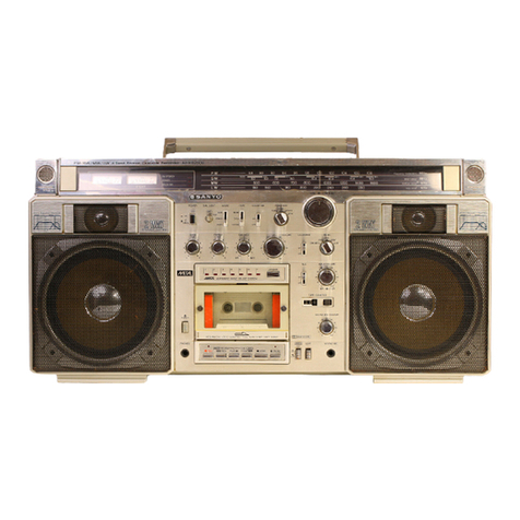
Sanyo
Sanyo M-1075C User manual

Sanyo
Sanyo M-G12 User manual

Sanyo
Sanyo VHR-350ES User manual

Sanyo
Sanyo MCD-Z46K User manual