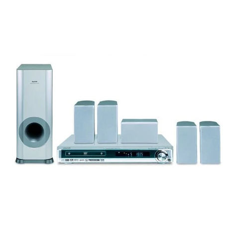
Sanyo DC-HT818 User manual

INSTRUCTION MANUAL
DVD HOME THEATER
DC-HT818

For your Attention..........................................................................2
Features & Package Contents .....................................................3-4
Remote Control..........................................................................5-6
Panel............................................................................................7
Connections.............................................................................8-10
System Setup.........................................................................11-16
Basic Playback........................................................................17-22
Trouble shooting..........................................................................23
Specifications..............................................................................24
Contents
-1-

For Your Attention
-2-
The lightning flash is intended to alert the user to the presence of dangerous
voltage within the product's enclosure, and touching the internal components may
result in a risk ofelectric shock to persons.
IMPORTANT NOTES
The exclamation markis intended to alert the userto the presence of important
operating instructions.
Please read through this manual before making connections and operating
this product. Retain this manual for future reference.
Don't open the cabinet of this unit. No user-serviceable parts inside. Refer
servicing to qualified personnel only.
Switch off the unit when you don't use it. Switch off the unit and disconnect it
from the AC powersupply when it is not being used for a long time. (Plug, as the
disconnected device entirely with power source, should keep in easy-to-
operation in dailylife.)
Don't install the unit in a place exposed to heating sources or direct sunshine.
Don't install the unit in a place exposed to moisture or rain.
The apparatus shallnot be exposedto dripping orsplashing and anyobject
filled with liquids,such as vasesshall not beplaced on it.
Install the unit on a horizontal, flat and firm surface with good ventilation.
Never block the vents which will cause malfunction resulting from overheating.
Use a softand clean clothto clean theoutside of theunit . Never clean it with
chemicals or detergent.
This book is only a guide for user's operation, not a criterion for configuration.
Only use attachments/accessories specified by the manufacturer.
WARNING: The batteries shall not be exposed to excessive heat such as
sunshine, fire or the like.
CAUTION: Danger of explosion if battery is incorrectly replaced.Replace only
with the same or equivalent type.
Do not install this apparatus in a confined space,such as a book case or
built-in cabinet.Minimum distance(about 100mm) around the apparatus for
sufficient ventilation.
TO REDUCE THE RISK OF ELECTRIC
SHOCK OR FIRE,DO NOT OPEN THE
COVER. REFER SERVICINGTO
QUALIFIED SERVICE PERSONNEL.
The following twolabels are on the back
of the mainunit:

Thank you for purchasing our product. Please read this manual
carefully before connection and operation and keep it for future
reference.
This DVD player is a new generation home player which can
produce high quality video and audio for your continued enjoyment.
Built in DolbyDigital, LPCM, MPEG etc. digital audio decoder
HiFi, 96kHz/24bit audiodigital processor
COAXIAL digital audio output
USB drive portand memory card slot
Compatible with DVD,VCD, CD, MP3, JPEG, Picture CD, etc.
Full function remotecontrol
AM/FM stereo tuningsystem
High quality amplifier
Features &Package Contents
-3-
Playable Disc and Media Types:
Symbol Contents
Disc types
Audio + Video
DVD
Audio
MP3
COMPACT
DIGITAL VIDEO
VIDEO CD
Audio + Video
Video-CD
VCD
Audio
CD-DA
JPEG Photo CD
Picture CD

Accessories:
A/V Cable
Remote Control
User Manual
Usermanual
FM Antenna Speaker Cable
AM Antenna
DVD REGION CODES:
DVD discs andplayers are coveredby a worldwide agreement which limits
playback of DVDdiscs to specific regions as determined by the software
manufacturer. Most DVDs come marked with a region coding. A disc specified
as playable in one region may not play on a player designed for a different
region. A discspecified as universal or with no region coding (Code ALL)may
be played in any region.
The regions are:
Region 1: Canada,USA
Region 2: Europe,Japan, Mid. East,South Africa
Region 3: South-East Asia
Region 4: Australia, Caribbean, Central & South America, New Zealand
Region 5: Africa, Former Soviet Union, India,North Korea, Pakistan
Region 6: China
THIS PLAYER PLAYS REGION 4 DISCS.
Features &Package Contents
-4-

Battery Installation
1Remove the battery compartment cover
on the back of the remote control.
2Load two AAA/1.5V batteries into the
battery compartment making sure that
the batteries have been inserted with the
correct polarities matchingthe symbols +,
- as indicatedinside the battery
compartment.
3Replace the cover.
Remote Control
-5-
Insert the batteriesinto the remote control. Point the remote control atthe remote
sensor on thefront panel. The remote control works within adistance of about
metres from thesensor and within an angle of about 30 degreesfrom the left and right
side.
7
Remote Control Operation
Battery Installation
NOTE:
Remove the batteries when you do not intend to use the remote control for a
long time.
Do not mixnew and usedbatteries, or different types ofbatteries.
Weak batteries can leak and severely damage the remote control.
Be environmentally friendly and dispose of batteries according to your
government regulations.
The batteries must not be exposed to excessive heat source, such as
sunshine, fire orany other thingslike that.

Remote Control
-6-
2
20
21
7
23
24
6
31
30
26
28
12
27
1
3
4
17
5
8
18
19
9
25
15
29
14
13
11
10
16
22
8 SEARCH+/-
9 AM/FM
11 MEMORY
TUNER:
23 RADIO+/-
24 AUTO
26 MO/ST
1 STANDBY/ON
2 DIGIT KEYS
3 GOTO
4 SETUP
5 A-MODE
6 PROGRAM
7 VOLUME+/-
8 FASTFORWARD/REWIND
9 TITLE
10 DIRECTION KEYS
[ ]/[ ]/[ ]/[ ]
11 AUDIO
12 S.EFFECT
13 STEP
14 USB/SD
15 REPEAT
16 OPEN/CLOSE
17 PLAY/ PAUSE
18 MUTE
19 V-MODE
20 ANGLE
21
22 OSD
23 NEXT/PREVIOUS
24 SUBTITLE
25 ENTER
26 MENU
27 CH-LEVEL
28 TONE
29 ZOOM
30 STOP
31 A-B REPEAT
FUNCTION

Panel
-7-
FRONT PANEL:
REAR PANEL:
1. POWER SWITCH
2. SPEAKER OUTPUT
3. COMPONENT VIDEOOUTPUT
4. LINE INPUT
5. 2-CH AUDIOOUTPUT
6. COAXIAL DIGITAL AUDIOOUTPUT
7. COMPOSITE VIDEOOUTPUT
8. FM ANTENNAJACK
9. AM ANTENNAJACK
1. MICROPHONE SOCKETS
2. DISC TRAY
3. MEMORYCARD SLOT
4. USB PORT
5. OPEN/CLOSE ( )
6. PLAY/PAUSE ( )
7. STANDBY/ON( )
8. STOP( )
9. VOLUMEADJUSTING KNOB
10. DISPLAY SCREEN

Connections
-8-
1 VIDEO SYSTEM CONNECTION
The following video outputs are available for this unit .
1.1 Composite Video
Use the yellow plug of an AV cable to connect the composite video output of
this unit to the video input of a TV/monitor.
Use a 3-core AV cable to connect the component outputs of this unit to the
corresponding inputs of a TV/monitor.
1. 2 Component Video
Notes:
Of the abovevideo outputs Use
the better availablevideo connection.
Don’t make allthe connections above at one time,otherwise the produced pictures
will be affected.
Only when thevideo settings conform to the actualvideo system connections does the
player produce thecorresponding video output. (Please refer tothe Video Setup in
System Setup chapter).
, component isbetter and composite video is standard.
DVD Player Video Output
TV/Monitor Video Input
Component Video Input
Y
Pb/Cb
Pr/Cr
YPb/Cb Pr/Cr
Component Video Output
VIDEO
VIDEO
Composite Video Input
Composite Video Output
Connections
-9-
Use a pair of AV cable (white for
left, red for right) to connect the
stereo audio outputsof this unitto
the stereo inputs of a TV or a
power amplifier.
The audio settingsshould conform tothe practical audiosystem connections.
Please refer to the Audio Setup in System Setup chapter.
2.2 Coaxial Digital Audio
Use a coaxialcable to connect
the coaxial outputof this unitto
the coaxial input of a power
amplifier.
2.1 Stereo Audio
2.3 Speaker Output
Use speaker cablesto connect
the speaker output terminals of
this unit to the corresponding
speakers.
2 AUDIO SYSTEM CONNECTION
The following audio outputs (2.1 2.3)are available for this unit .
TV/Monitor/Amplifier Audio Input
DVD Audio Output
Connections
-9-
Use a pair of AV cable (white for
left, red for right) to connect the
stereo audio outputsof this unitto
the stereo inputs of a TV or a
power amplifier.
The audio settingsshould conform tothe practical audiosystem connections.
Please refer to the Audio Setup in System Setup chapter.
2.2 Coaxial Digital Audio
Use a coaxialcable to connect
the coaxial outputof this unitto
the coaxial input of a power
amplifier.
2.1 Stereo Audio
2.3 Speaker Output
Use speaker cablesto connect
the speaker output terminals of
this unit to the corresponding
speakers.
2 AUDIO SYSTEM CONNECTION
The following audio outputs (2.1 2.3)are available for this unit .
TV/Monitor/Amplifier Audio Input
DVD Audio Output
COAXIAL
COAXIAL
Digital Audio Output
Digital Audio Input
Notes:
R
L
Connections
-9-
Use a pair of AV cable (white for
left, red for right) to connect the
stereo audio outputsof this unitto
the stereo inputs of a TV or a
power amplifier.
The audio settingsshould conform tothe practical audiosystem connections.
Please refer to the Audio Setup in System Setup chapter.
2.2 Coaxial Digital Audio
Use a coaxialcable to connect
the coaxial outputof this unitto
the coaxial input of a power
amplifier.
2.1 Stereo Audio
2.3 Speaker Output
Use speaker cablesto connect
the speaker output terminals of
this unit to the corresponding
speakers.
2 AUDIO SYSTEM CONNECTION
The following audio outputs (2.1 2.3)are available for this unit .
TV/Monitor/Amplifier Audio Input
DVD Audio Output
COAXIAL
COAXIAL
Digital Audio Output
Digital Audio Input
Notes:
R
L
L
R
2CH Audio Output
2CH Audio Input

Connections
-10-
LLRR
LLRR
2-CH AUDIO OUTPUT
LINE INPUT
DVD Audio Input
Audio Output of Extra Devices
2.4 Line Input
This unit has a group of stereo
audio input terminals, i.e. LINE
INPUT (on the rear panel). You can
input the analogue stereo audio
signals from extra device such as
DVD, VCD, CD, VCR player, etc by
connecting it viathe input terminals.
Use the audiocable (white forleft ,
red for right) to connect the stereo
audio output terminals of a DVD,
VCD, CD, VCR player, etc to the
stereo input terminalsof this unit.
After the connections have been
correctly made, press[ ]
to switch to the corresponding
signal source LINE to enjoy the
audio from theconnected extra
device.
FUNCTION
2.5 FM/AM CONNECTIONS
AC POWER CONNECTION
After checking allthe connections have been made correctly,plug theAC power leadof
this unit intothe wall socket,then switch the powerswitch to the on position .
NOTE:
Unplug theAC power lead from the wallsocket if the unit will notbe in use for a
prolonged period oftime.

MENU OPERATION
1. Press [SETUP]on the remote control to displaythe setup menu.
2. Press [ ]/[ ] to selectan item. The submenu of the selected itemwill be displayed
below instantly.
3. Press [ ]/[ ] to selectan item youdesire to set in the submenu, then press
[ENTER] /[ ]to enter.Use [ ]/[ ] to selectan option, then press [ENTER] toconfirm
it, or press[ ] to cancel.
4. Then you can press [ ]/[ ] to continueto set other items in thesubmenu.
5. Press [ ] to goback to the upper menu ofthe current one.
6. Press [SETUP]again to exit the setup menu.Alternately, move the highlight to' ',
then press [ENTER]to exit the setup menu.
1 GENERAL SETUP PAGE
1.1 TV DISPLAY
If the unitis connected to a conventional TV set, select4:3 PANSCAN or 4:3
LETTERBOX. The 4:3 image will be displayed in full screen inits native aspect ratio.
4:3 PANSCAN: The wide-screen imagewill be displayed on the screenin its native
aspect ratio withsome part on the left andright cut off.
4:3 LETTERBOX: The wide-screen imagewill be displayedin its native aspect ratio
with black bandson the upper and lower sectionsof the screen.
16: 9: If the unitis connected toa wide-screen TV set, selectthis option. The wide-
screen image willbe displayed in full screen inits native aspect ratio while the 4:3
image will bestretched out horizontally to fit inthe screen.
1.2 ANGLE MARK
Set this itemto ON. When adisc encoded with multiple camera anglesis playing, the
angle mark willdisplay on the screen. Then you can viewthe video of different camera
angles by pressing[ANGLE] on the remote control.
Set this itemto OFF to disable thisfunction.
NOTE: This function only works withthose discs encoded with multiple cameraangles.
1.3 OSD LANGUAGE (On-Screen Display Language)
Set the on-screendisplay language with this item.(ENGLISH,DANISH,SWEDISH)
1.4 CLOSED CAPTIONS
Set this itemto ON. When adisc encoded with closed captions, theclosed captions
will be shownon the screen. Set this item to OFF to hide it.
You can also press [SUBTITLE] on theremote control to show or hidethe closed
captions.
NOTE: This function only works withthose discs encoded with closed captions.
1.5 SCREEN SAVER
ON: If theimage remains motionless on the screen, for example thedisc is paused,
stopped etc, forseveral minutes, a screen saver will appear on thescreen. You can
press any keyor button except [STANDBY/ON] to wake itup.
OFF: Disable the screensaver function.
System Setup
-11-

System Setup
-12-
1.6 LAST MEMORY
ON: During playbackor in the paused/stopped status each time you openthe disc tray
or turn off the player, the unitwill memorize the last playback time.Next time when you
insert the samedisc and close the disc tray to load thedisc, the unit will play fromthe
memorized point.
OFF: Disable thelast memory function.
2 AUDIO SETUP PAGE
2.1 ANALOG AUDIO SETUP
2.1.1 DOWNMIX
LT/RT: The 5.1-channel audio is mixed into left channeland right channel and is
output via theFL and FR speakers respectively.
STEREO: The 5.1-channel audiois mixed into stereo signal andis output via the FL
and FR speakers.
3D SURROUND: This mode createsa virtual surroundeffect from stereo or multi-
channel audio contents.
5.1CH: Turn offthe DOWNMIX mode. If the unitis connected to a 5.1-channel
amplifier, thisitem should be selected.
NOTE: This function onlyapplies to the Dolby AC-3 encoded 5.1-channel discs.
2.1.2 FRONT, CENTER, REAR SPEAKER and SUBWOOFER
Only when theDOWNMIX mode is turned off (DOWNMIX is set to 5.1CH) are the
CENTER SPEAKER and REAR SPEAKER activated. The FRONT SPEAKER can be
set to LARGE or SMALL. The CENTER SPEAKER, REAR SPEAKER can be setto
LARGE, SMALL or OFF and the SUBWOOFER can be setto ON or OFF.
NOTE:
If the speakeris set to LARGE, the output level will be higher than that of SMALL.
If the speakeris set to SMALL, the output level will be lower than that of LARGE.
If a speakeris set to OFF, no audiois output from it.
2.1.3 DIALOG
When DOWNMIX is set toLT/RT or STEREO, this item is available.
Adjust the valueof this item to control thedialog volume.
NOTE: When playing 5.1CHdisc, this item can be usedto adjust the volume of the
speakers.
2.1.4 D.R.C. (Dynamic Range Control)
You can set this item to AUTO, ON or OFF.
2.2. DIGITAL AUDIO SETUP
2.2.1 DIGITAL OUTPUT
SPDIF/OFF: There will beno digital audio signal output. (Coaxial off)
SPDIF/RAW: The digital audiosignal output will be in its raw format. Normally, this
mode is usedfor DTS & Dolby Digital 5.1 signals.
SPDIF/PCM: The digital audiosignal output will be in PCM format. Normally, this
mode is usedfor audio CD signals.

System Setup
-13-
2.2.2 LPCM OUT
When DIGITAL OUTPUT is set toSPDIF/PCM, this itemis available.
Select a samplerating for the digital audio output.There are two options, 48KHzand
96KHz.
NOTE: Some amplifiers don'tsupport 96KHz sampling which will affect the coaxial
output.
2.3 DOLBY DIGITAL SETUP
2.3.1 DUAL MONO
STEREO: The player outputsthe left-channel audio and right-channel audio via the
FL and FR speaker respectively.
L-MONO: The player outputsthe left-channel audio only via both the FL and FR
speaker.
R- MONO: The player outputsthe right-channel audio only via both the FL and FR
speaker.
MIX- MONO: The player outputsthe average signalof the left-channel and right-
channel audio viathe FL speaker and theFR speaker.
NOTE: This function onlyapplies to the Dolby AC -3 encoded 2-channeldiscs.
2.3.2 DYNAMIC
When you watchfilms with large dynamic scope in low volume, forexample at night,
you can adjustthe dynamic value up to avoid losing sound detailsresulting from the
low volume.
2.4 CHANNEL DELAY
This item isused to set the delay timefor the center, rear speakersand the subwoofer.
The delay isto compensate for the audio propagationtime difference caused by the
distance difference of the speakers to the listener.
Use the directionkey [ ]/[ ] to selecta speaker, center speaker,subwoofer, left
surround speaker orright surround speaker. Then use the directionkey [ ]/[ ] to set
the distance difference.
0cm
Sub
Woofer
NOTE:
The unit doesnot support delays for when thedistance
between the centeror surround speakers and the listener
are longer thanthat between the front speakers andthe
listener.
In case thechannel delay settings cannot match your
speaker configuration, pleaseset all distance difference
to 0cm. Ifpossible, use your receiver/amplifier to setthe
channel delay.
2.5 EQUALIZER
2.5.1 SOUND MODE
Select a desiredsound mode in this item.
2.5.2 BASS BOOST
Set it toON to boost the bass sound.
2.5.3 SUPER BASS
Set it toON to get the super bass sound effect.
2.5.4 TREBLE BOOST
Set it toON to boost the treble sound.

System Setup
-14-
2.6 3D PROCESSING
3D processing providesa virtual surround sound experience usingjust two speakers.
2.6.1 PRO LOGIC II
Pro Logic II:This unit allows you toconfigure Dolby Pro Logic II toexpand 2-channel
source audio intofull 5.1-channel surround sound.
NOTE: Pro Logic IIfunctionality is effective only when DOWNMIX is set to5.1CH .
2.6.1.1 PRO LOGIC II
This item isused to turn on or off the ProLogic II processing.
ON: Pro Logic IIprocessing is always on.
OFF: Pro Logic IIprocessing is disabled
AUTO: Pro Logic IIprocessing is on only when DolbyPro Logic II encoded content is
detected.
NOTE: When the ProLogic II processing is turned off, all thefollowing items (MODE,
PANORAMA, DIMENSION and CENTER WIDTH) are unavailable.
2.6.1.2 MODE
This item isused to set the processing mode of Pro LogicII.
MUSIC: The surround experienceis tailored for multi-channel music playback.
MOVIE: Emphasis is givento the center channel as two-channel audio is decodedand
played back intoyour 5.1 system.
PRO LOGIC: This activates decodingand processing of the original Dolby Pro Logic
processing with mono-surround channel. We recommend using the Dolby Pro Logic
Movie mode inlie of this 4-channel surround format.
AUTO: Automatically selects processing mode based on the input format.
2.6.1.3 PANORAMA
This item isused to turn on/off panorama mode and is available only whenMODE is
set to MUSIC.
When panorama modeis turned on, the front stereoaudio is partially fed into the
surround channels foran enveloping effect.
2.6.1.4 DIMENSION
This item isavailable only when MODE is set toMUSIC.
This item allowsgradual adjustment of the soundfield eithertowards the front or
towards the rear. This is useful insetting a more even balance fromall speakers with
some rooms.
2.6.1.5 CENTER WIDTH
This item isavailable only when MODE is set toMUSIC.
This item canbe used to control the widthof the center channel sound effect by
blending the centerspeaker to the left and rightspeakers. As the level number
increases, the centerchannel sound moves toward the leftand right speakers.
2.6.2 REVERB MODE
You can select areverb mode in this item.

System Setup
-15-
2.7 HDCD(High Definition Compatible Digital)
HDCD (High DefinitionCompatible digital) is a patented encode/decodeprocess for
delivering the fullrichness and details of the soundfrom HDCD-encoded CDs.
2.7.1 FILTER
You can set the digital filter to 2x, 1x or off.
2.8 KARAOKE SETUP
2.8.1 MIC SETUP
2.8.1.1 MIC
Set this itemto ON/OFF to switch on/off the connectedmicrophone(s).
2.8.1.2 MIC VOL
Enter this item,then use direction key [ ]/[ ] to adjust the microphone volume.Then
press [ENTER] toconfirm your adjustment.
3 VIDEO SETUP PAGE
3.1 VIDEO OUTPUT
YUV: Set video outputin analog component video format ifthe component video
outputs are used.
P_YUV: Set video outputas progressive YUV signals ifthe component video outputs
are used.
NOTE: If the videosetting differs from the actualvideo connection, you may get no
image or verypoor image on the TV. In such case, you needreset this setting item for
an appropriate videooutput mode or press [V-MODE]on the remote control until the
output image becomesnormal.
3.2 COLOR SETTING
3.2.1 SHARPNESS
There are threeoptions (HIGH, MEDIUM and LOW) for youto choose inthis item.
3.2.2 BRIGHTNESS, CONTRAST, HUE and SATURATION
Enter these itemsrespectively, use direction key[ ]/[ ] to adjust the value, then
press [ENTER] toconfirm it.
3.2.3 GAMMA
There are fouroptions (HIGH, MEDIUM, LOW and NONE) for youto choose inthis
item.
3.2.4 LUMA DELAY
There are twooptions (0T and 1T) for youto choose inthis item.
4 PREFERENCE PAGE
If there's nodisc in the disc tray orthe disc tray is open ,this item is available.
2.8.1.3 ECHO LEVEL
Enter this item,then use direction key [ ]/[ ] to adjust the microphone echolevel.
Then press [ENTER]to confirm your adjustment.
OFF: Set videooutput to the composite.

System Setup
-16-
4.1 TV TYPE
4.2 PBC (Play Back Control)
ON: Activate the PBCfunction. When playing a disc encodedwith PBC function such
as VCD 2.0disc, press [MENU] to return tothe PBC menu.
OFF: Disable the PBCfunction.
NOTE: This function onlyworks with those discs encoded withPBC function .
DVD, VCD1.1, CD-DAand MP3 discs have no PBCmenu.
4.3 AUDIO, SUBTITLE and DISC MENU
Select a preferredaudio language, subtitle language and discmenu language in these
items.
You can also makeselection of the audio language by using the [AUDIO],and the
subtitle language withthe [SUBTITLE] on the remote control.
NOTE: If the selectedlanguage is not available for thecurrently playing disc, the
disc's default settingwill remain enabled.
4.4 PARENTAL
This item allowsthe user to set a maximumrating of the movies that canbe viewed.
Movies rated higherthan the level set for theparental lock can not be viewedwithout
inputting the correctpassword. What's more, to key inthe correct password is needed
to reset thelevel. The default password is136900.
NOTE: This function onlyworks with those discs that haveparental rating encoded
into them.
4.5 DEFAULT
Enter to restoreall the default settings except thesettings in PARENTAL item and
PASSWORD setup page.
5 PASSWORD SETUP PAGE
5.1 PASSWORD MODE
You can switch on/off the password function in thisitem.
NOTE: Youmust key in the correct passwordand press [ENTER] to confirm before
you change theoption in this item. The default password is136900.
5.2 PASSWORD
You can reset thepassword in this item.
NOTE: The default password(136900) is always active even ifthe password has been
reset.
This product supportsboth NTSC (National Television System Committee) and PAL
(Phase AlternatingLine) television broadcasting standards.
PAL : If theconnected TV is PAL system, select this mode.The video signal ofa NTSC
disc will beoutput in PAL format.
AUTO: If theconnected TV is multi system, select this mode. The output format of
video signal willbe in accordance with the videosignal of the disc.
NTSC: If theconnected TV is NTSC system,select this mode. The video signal of a
PALdisc will be output in NTSCformat.
NOTE: If a wrongselection is made, the viewing imagewill be very poor. In such case,
you are supposedto change the option in thisitem to fix the error.

Press repeatedly toadvance the video frame by frame. Press [ ]to
resume the normalplayback. (Applies to DVD, )VCD discs etc
Press once topause a playback, then press [ ] to continuethe playback;
Press it twiceto stop a playback and the disc will bereset to the starting
point.
STEP
Basic Playback
GOTO
Press to enteran item in the menu orto confirm and execute a selection.
The direction keyscan be used to move thehighlight in the menu.
Press to open/close the disc tray.
STANDBY/ON
SETUP
Press to switchon the unit. Press it againto put the unit in standbymode.
Press to enter/exitthe setup menu.
The digit keyscan be used to input numbersor make selection of a track
or a chapter, etc.
This button isused to locate a position ona disc that you want aplayback to
begin from. Pressthis button, then use the directionkeys and digit keys to
set a specifictrack, disc time, track time, chapter, title, chaptertime or title
time of adisc to go to directly.
Press this buttonto enter/exit the program menu withwhich you can
playback the contentsof a disc in your desiredorder.
In the programmenu, use the direction keys anddigit keys to make a
program list, thenmove the highlight to START and press [ENTER]to start
program playback.
During program playback,press [PROG] to enter the programmenu. Now,
STOP is highlighted. Press[ENTER] to cancel the current program
playback.
PROGRAM
Press to startor pause a playback. Or,press to return to the normal
playback from thefast forward, fast reverse playback, etc.
Press for fastforward playback.
Press for fastreverse playback.
Press repeatedly toswitch to the available extra signalsource USB or
SD/CARD, or toreturn to the DVD mode.
USB/SD
FUNCTION Press repeatedly toswitch among TUNER mode, LINEmode and DVD
mode.
-17-
Press to returnto the previous chapter/track.
Press to skipto the next chapter/track.
Press repeatedly toswitch the repeat modes. (Note: For VCD2.0 disc, this
function is invalidwhen PBC function is activated.)
REPEAT
5566
8899
10+10+
0/100/10
2233
11
44
7799
ENTER

ZOOM
You can repeat aspecific section of a disc withthis button.
During playback, pressthis button to mark down thestarting point (A) and
press it againto mark down the ending point(B). Then, the unit willplayback
this section overand over again. Press it foronce more to cancel A-Brepeat
and resume thenormal playback.
Note: PointsA and B must bein the same title/ track.
A-B
MUTE Press this buttonto switch off the soundtemporarily. Press it again to
switch it on.
VOLUME+/- Press [VOLUME+] to turn up thevolume; press [VOLUME-]to turn down
the volume.
Press repeatedly toswitch the sound effects or switch off the sound effect.
Note: You are recommended to switch off the soundeffect when playing a
Dolby 5.1 channeldisc so that to obtain thereal 5.1 effect.
S.EFFECT
Press this keyrepeatedly to select a channel orthe overall volume, then
press [VOLUME+]/[ VOLUME-]to adjust its level.
CH-LEVEL
TONE Press to selectBASS or TREBLE, then use[VOLUME+/-] to control the
level of bassor treble.
Basic Playback
-18-
Press to enterthe title menu of the playingDVD disc.
Press to returnto the root menu.
It works as[PBC] for disc encoded with PBCfunction such as VCD 2.0
disc. Press itto activate/ disable the PBC function.
Press repeatedly toswitch the subtitles or switch off the subtitle function.
(Note: This function only works with those discs encoded with subtitles.)
Press repeatedly toswitch or hide the relative informationof the playing
disc.
Press repeatedly toselect the available audio languages provided by the
disc (for DVD).
Press repeatedly toswitch the available audio channels (LEFT-MONO,
RIGHT-MONO, MIX-MONOand STEREO) provided by the disc(for VCD).
Press to switchthe viewing angles.
(Note: This function only works with the discs encoded with multiplecamera
angles.)
Press repeatedly toswitch the video output modes.
Press repeatedly toswitch the audio output modes between5.1
CHANNELS OUTPUT and STEREO OUTPUT.
Press this buttonto zoom in/ out the scene.In zoomed-in mode, the
direction keys canbe used to move the zoomingcenter.
(Note: Appliesto DVD, VCD etc)
TITLE
MENU
SUBTITLE
OSD
AUDIO
ANGLE
V-MODE
A-MODE

USB DRIVE AND MEMORY CARD PLAYBACK
Basic Playback
-19-
Insert a USB drive in the USB port, then press [USB/SD] to enter the
connected USB driveand you canplayback the readablefiles in it.Press
[USB/SD] again to switch back to DVD mode.
Insert an SDcard into thememory card slot,then press [USB/SD] to access
the connected memorycard and youcan playback thereadable files init.
Press [USB/SD] again to return to DVD mode.
NOTE:
In case the player breaks down when you insert a USBdrive or amemory
card into the player, turn off the player, disconnect the power cord from the
AC outlet and unplug the USB drive or/and the memory card from the player.
Then, power onthe player again.The player will resume thenormal status.
For playback operation,please refer toMP3 DISC PLAYBACK in this chapter.
If a USB drive anda memory cardare inserted inthe player atthe same
time, press [USB/SD] once to select USB and press it twice to select the
memory card. Press it for the third time to return to the DVD mode.
The USB and SD function is only available under DVD mode.
USB MEMORYDEVICE OPERATION
IMPORTANT INFORMATIONS
- Copyright protectionfiles cannot be played back.
- Copyright protectionfiles on theUSB memory
device are skipped automatically when played
back.
- Recommended use:
Flash memory type USB memory player
- Not recommended:
Hard disc memory type USB player
- Some Flash memory player will not play
successfully with thisuint.
SD CARD OPERATION
IMPORTANT INFORMATIONS
- Copyright protection files cannot be
played back.
- Copyright protectionfiles on SD/MMC
card are skipped automatically when
played back.
Table of contents
Other Sanyo Home Theater System manuals

Sanyo
Sanyo DVR-HT120 User manual

Sanyo
Sanyo DC-PT100 User manual

Sanyo
Sanyo DC-TS750 User manual

Sanyo
Sanyo DC-TS780 User manual

Sanyo
Sanyo DWM-2500 User manual

Sanyo
Sanyo DC-AVD8501 User manual

Sanyo
Sanyo DC-TS3000 User manual

Sanyo
Sanyo DC-TS765KR User manual

Sanyo
Sanyo DCS-AVD8501 User manual

Sanyo
Sanyo DWM-3500 User manual

Sanyo
Sanyo DC-PT100XE User manual

Sanyo
Sanyo DC-TS780 User manual

Sanyo
Sanyo DWM-3900 User manual

Sanyo
Sanyo DWM-2600 User manual

Sanyo
Sanyo DC-AVD8501 User manual

Sanyo
Sanyo DC-DAV821 User manual

Sanyo
Sanyo DC-TS760 User manual

Sanyo
Sanyo DC-TS765KR User manual

Sanyo
Sanyo DVR-HT120 User manual

Sanyo
Sanyo HTD-5201 User manual