Sanyo DC-X850 User manual

FILE NO.
Service Manual
Specifications
TURNTABLE SECTION
Type ................
Rated speed . . . . . . . . . .
TUNER SECTION
Reception frequency . . .
CD PLAYER SECTION
Channels ............
Sampling frequency ....
Pick-up ..............
Laser output ..........
Wavelength ..........
Frequency response . . . .
Wow&Flutter ., ..,...
Digital Stereo
Sound System
1’ I
I
IIII! f II
!!——
II
Belt drive auto-return
33113, 45rprn
FM:87.5-108MHz
AM:53i -l,602kHz
(9kHz step)
2-channels stereo
44.1 kHz
0ptica13-beam semiconductor
laser
0.6 mW(Continuous wave max.)
790 nm
20 HZ-20,000HZ
Below measurable limits
DC-X850 (AU)
PRODUCT CODE No.
129 454 02
CASSEITE DECK SECTION
Track system .........
Frequency response ....
Signal-to-noise Tatio ....
Wow&Flutter . . . . . . . .
Fast forwardi -
rewind lime ......
GENERAL
Output power .........
Inputs ..............
outputs .............
Power requirements . . . .
Power consumption ....
Dimensions . . . . . . . . . .
Weight . . . . . . . . . . .. . . .
t.
4-track, 2-channels stereo
60 Hz -14,500 Hz (Cr02 tape)
60 Hz -13,500 Hz (Normal tape)
60 dB (Dolby NR ON)
0.15 v. (WRMS)
Approx. 110 sec. (C-60)
20 Wx 2 (at 4ohms,
10 “L distortion )
VIDEO :400 mV /50k ohms
SPEAKERS: 4ohms
PHONES :8-32 ohms
AC :230-240 V, 50 Hz
75 w
350 (W) x 423 (H) x 369 (D) mm
8.2 kg
Specifications subject to change without notice.
REFERENCE No. SM580639

i
CONTENTS
SPECIFICATIONS ....................... TOP CD PLAYER MECHANISM ADJUSTMENTS . . . . 8
LASER BEAM SAFE1-y PRECAUTIONS . . . . . . . 1CD PLAYERADJUSTMENTS .............. 11
REMOVAL AND INSTALMTION . . . . . . . . . . . . 2EXPLODED ViEW ...................... 13
TAPE DECKADJUSTMENTS .............. 3PARTS LIST .......................... 14
AMPLIFIER ADJUSTMENTS ............... 5ICBLOCKDIAGWM . . . . . . . . . . . . . . . . . . . . 27
REPLACEMENT OFSTYLUS . . . . . . . . . . . . . . 6SCHEMATIC DIAGRAM .................. 30
SCHEMATIC &WIRING DIAGRAM (TURNTABLE) 6WIRING DIAGRAM ...................... 32
TUNER ADJUSTMENTS .................. 7IC DESCRIPTIONS ...................... 46
LASER BEAM SAFETy PRECAUTIONS
●Pick-up that emits alaser beam is used in this CD player.
CAUTION:
USEOFCONTROLS ORADJUSTMENTS
ORPERFORMANCE OFPROCEDURES
OTHERTHANTHOSE SPECIFIED
HEREINMAYRESULT INHAZARDOUS
RADIATION EXPOSURE
LASER OUTPUT. .......0.6 mW Ma. (CW)
WAVELENGTH ........... 790nm
-.
-.
,,.
\
–l-

i
-—. . . . . .-. ,
:MOVAL AND INSTALLA IlUN
I
I
)
)
)
)
Disconnect the power cord’s plug from the electrical outlet.
All wiring should be returned to the original position after work is completed.
First have ready many the new FIXERS (61 4129 2496) for replacement.
Arrange the lead wires so that they are not near the heat sink.
CABINET
Remove the 2turntable mounting screws. (~)
Remove the 12 slide panel mounting screws. (@)
Remove the 5rear panel mounting screws. (@)
Remove the 5front panel mounting screws. (@)
b. WIRING LAYOUT
.Power Transformer
.
-2-
,.’
,:, ,
,.
..

TAPE DECK ADJUSTMENTS —
a. PREPARATIONS FOR ADJUSTMENTS
●Measuring instruments, tools. (4)
(1)
(2)
(3)
b.
(a)
(1)
(2)
(3)
(4)
c.
(a)
(1)
(2)
(3)
(4)
(5)
‘6)
b)
1)
!)
‘)
)
Test tape MTT-114M (10 kHz)
TCW-211 (1,500 Hz) (Optionat)
MTT-111 (3,000 Hz) (5)
(6)
AC-224 (NORMAL)
Oscilloscope :(At least 10 MHz, dual channel) (7)
(8)
Digital voltmeter (Input impedance 1MQ or more)
HEAD REPLACEMENT AND AZIMUTH ADJUSTMENT
Head replacement
Automatic distortion analyzer or AC voltmeter
( - 80dB, input impedance 1Ma or more)
AF-oscillator (400 Hz, 500 mV RMS)
Frequency counter (5 MHz or more)
Frequency counter, probe.
Screwdrivers (non-metalic) for adjustments.
After replacement, demagnetize the heads by using adegausser.
Be sure to clean the heads before attempting to make any adjustments.
Be sure both channels (1 and 2) are the same level (Using adual-channel oscilloscope).
All wiring should be returned to the original position after work is completed.
TAPE ‘“B’”
TAPE “A ‘“ E. HEAD R/P HEAD
PLAY HEAD
&y!i!!iiT
YELLOW
TAPE “A” &“B” f+EAD AZIMUTH ADJUSTMENT
Head adjustment
Load atest tape in Tape Deck”A” (MTT;lI 4N, etc.: 10 kHz)
for azimuth adjustment.
Press the PLAY (›) button.
Use aflat-tip ( - ) screwdriver to turn the screw for normal
azimuth adjustment so that the left and right outputs are
maximized at the same phase during playback.
Press the STOP button.
Repeat procedure for Tape Deck” B”.
L1
‘L LWHITE
BLUE
TAPE
After completion of the adjustment, use threadlock
(TB1401 B)to secure the azimuth-adjustment screws.
Phase alignment
Prepare adual-channel oscilloscope.
Set so that the left and right ranges of the oscilloscope are the same.
Play the test tape (MTT-114N, etc.: 10 kHz).
Adjust so that the waveforms for the left and right channels are in
alignment, as shown in the illustration.
-3-
Phase alignment ~

i
TAPE DECK ADJUSTMENTS
d. MOTOR REPLACEMENT AND SPEED ADJUSTMENT m\
.
(a)
(l)”
(b)
●
(c)
(1)
(2)
(3)
(4)
(5)
(6)
(7)
(d)
(1)
(2)
(3)
(4)
Motor speed adjustments
Make the adjustment near where the test tape finishes (
winding.
Normal speed >0
ITAPE
insert the test tape (MTT-1 11, etc. 3,000 Hz) into I
Tape Deck A. I
Press Tape Deck As PLAY button. SHORT
Adjust VR309 so that the frequency counter shows *;:;:
HIGH SPEED
areading of 3,000 Hz. TEST POINT
Press Tape Deck A’s STOP button. -<
Insert the test tape into Tape Deck B. ti
VR309
‘PEED:EOU(%
o
Checking the frequency counter shows areading of
3,000 Hz (-40, +40 Hz).
Press Tape Deck B’s STOP button.
-. .
High speed
Insert the test tape (TCW-2 11, etc. 1,500 Hz optional) (5)
into Tape Deck A. (6)
Press Tape Deck A’s PLAY button. (7)
Set to the high-speed condition.
Short-circuit test points J3438 and J3439.
Press Tape Deck B’s PLAY button. ‘&@El
Checking the frequency counter reading is 3,000 Hz.
Press Tape Deck A’s STOP button.
After the completion of the adjustment, remove the
short-circuit between test points J3438 and J3439.
e. CHECKING THE MECHANISM TORQUES
.Clean the head, capstan and pinch roller before mak!ng any measurement.
IMeasurement
F%%-
F.FWD /REW
Take-up torque Back tension Tape terision
PLAY:TW-2111A Drive-power cassette
F.FWD/REW:TW-2231 PLAY:TW-21/t’A TW-2412
30-60 gr.cm 1.5- 4.5 gr.cm 60gr or more
55- 120qr.cm
-4-

.
AMPLIFIER ADJUSTMENTS
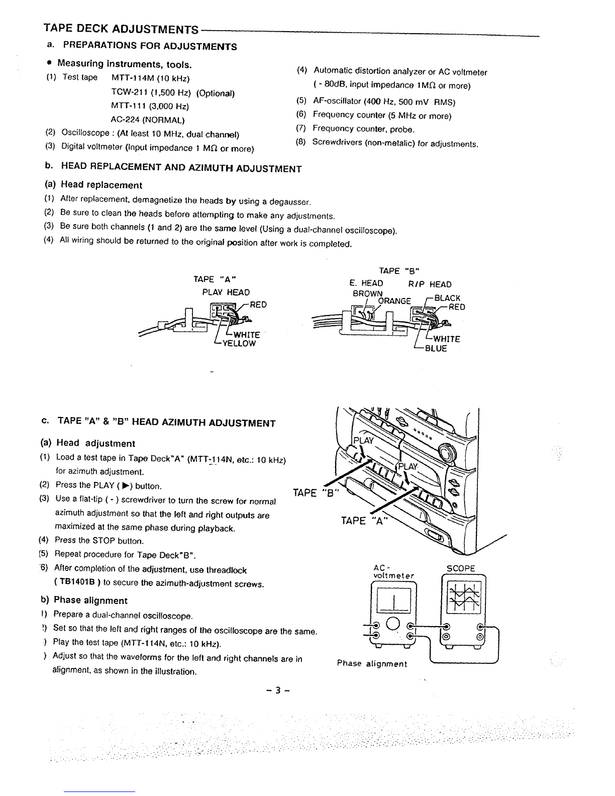
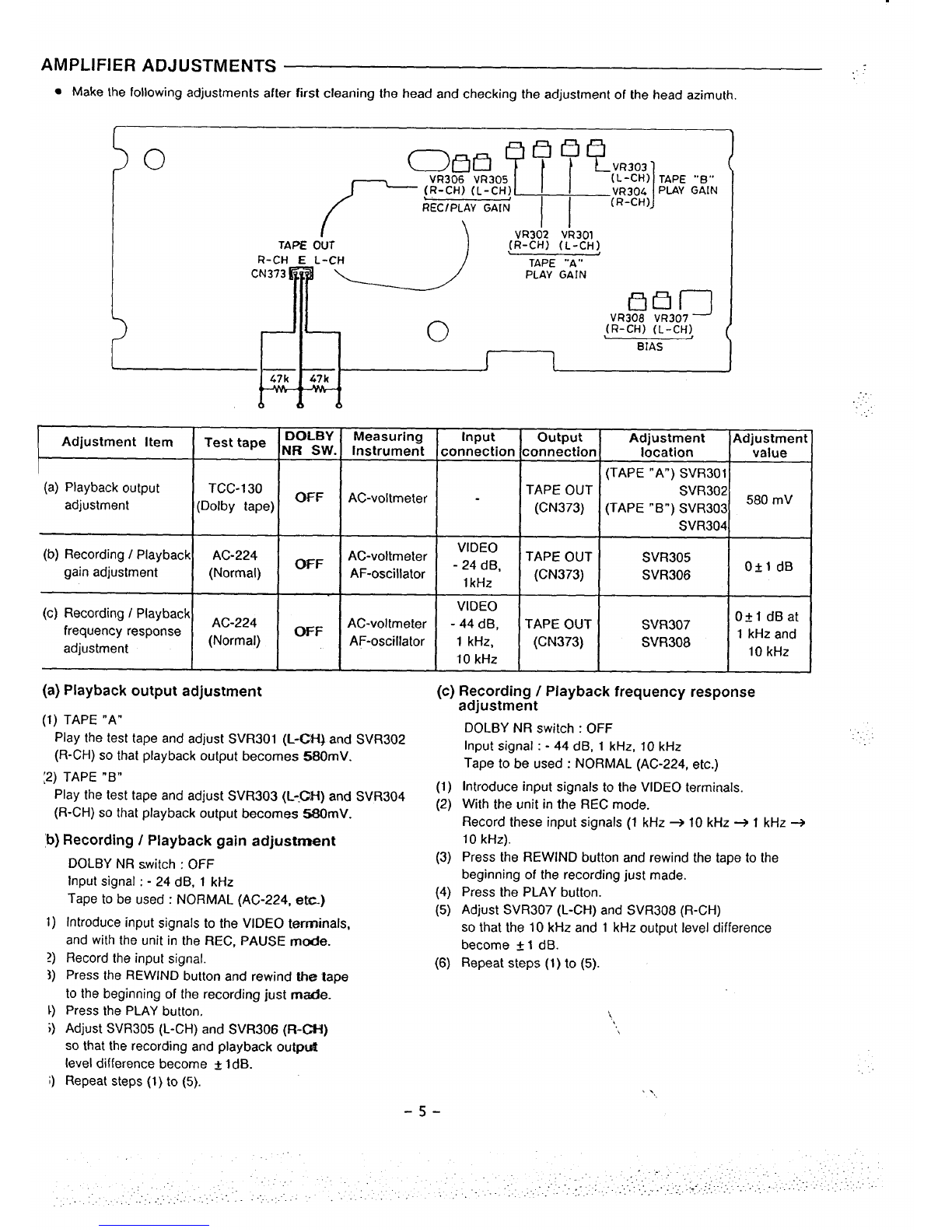
.Make the following adjustments after first cleaning the head and checking the adjustment of the head azimuth.
t\
/_!!f2J’~pgq,,,G:,N ~
RR5mimsm (R-CH)
Id”
VR302 VR301
TAPE OUT (R-CH) (L-CH)
R-CH EL-CH TAPE ‘“A“
CN373 PLAY GAIN
Immg
o
VR308 VR307
(R-CH) (L-CH) (
BIAS
1
x67 k)
o&6
Adjustment Item Test tape ;~OLsB;,
(a) Playback output TCC-130
adjustment (Dolby tape) CWF
(b) Recording IPlayback AC-224 ~F
gain adjustment (Normal)
(c) Recording IPlayback Ac *24
frequency response -
adjustment (Normal) ‘F
Measuring input output Adjustment Adjustment
Instrument connection connection location value
III(TAPE “A”) SVR3011
AC-voltmeter -TAPE OUT SVR302
(CN373) (TAPE “B”) SVR303 580 ‘v
SVR304
VIDEO
AC-voltmeter -44 dB, TAPE OUT SVR307 Otl dBat
AF-oscillator 1kHz, (CN373) SVR308 1kHz and
10 kHz 10 kHz
(a) Playback output adjustment
(1)TAPE “A”
Play the test tape and adjust SVR301 (L-CH) and SVR302
(R-CH) so that playback output becomes !N30mV.
:2) TAPE “B”
Play the test tape and adjust SVR303 (L-.f3-t) and SVR304
(R-CH) so that playback output becomes 580mV.
b) Recording /Playback gain adjustment
DOLBY NR switch :OFF
Input signal :-24 dB, 1kHz
Tape to be used :NORMAL (AC-224, etc-)
Introduce input signals to the VIDEO terrrrinals,
and with the unit in the REC, PAUSE mode.
Record the input signal.
Press the REWIND button and rewind the tape
to the beginning of the recording just made.
Press the PLAY button.
Adjust SVR305 (L-CH) and SVR306 (R-Ct-1)
so that the recording and playback outpdt
level difference become f1dB.
Repeat steps (1) to (5).
(c)
(1)
(2)
(3)
(4)
(5)
(6)
Recording /Playback frequency response
adjustment
DOLBY NR switch :OFF
Input signal :-44 dB, 1kHz, 10 kHz
Tape to be used :NORMAL (AC-224, etc.)
Introduce input signals to the VIDEO terminals.
With the unit in the REC mode.
Record these input signals (1 kHz +10 kHz +1kHz +
10 kHz).
Press the REWIND button and rewind the tape to the
beginning of the recording just made.
Press the PLAY button.
Adjust SVR307 (L-CH) and SVR308 (R-CH)
so that the 10 kliz and 1kHz output level difference
become ~1dB.
Repeat steps (1) to (5).
..
.-,”.
,,
:.”
‘\,
5-

i
REPLACEMENT OF STYLUS
After along period off use or when an inferior sound is obtained,
the stylus assembly should be replaced with anew one.
To remove the stylus assembly, pull it downwards gently.
To mount the new one, re-assemble in reverse order.
SCHEMATIC &WIRING DIAGRAM (TURNTABLE)
CARTRIDGE
STYLUS
STYLUS PROTECTION
J. LH,I,
!
x------ --- 111
RL
[GND
CARTRIDGE CONNECTOR
-. TURN TABLE
P.W.B
IIJ
IAUTO SHUT-OFF
SWITCH
TURN TABLE
MOTOR
L33 RPM
3
L5RPM
,“ SPEED SELECT
.0 SWITCH
-6-

TUNER ADJUSTMENTS
●
●
●
●
●
●
Use aplastic screw driver for adjustments.
Speaker impedance :4 ohm
Standard Output :500 mW
FM MODE switch :STEREO
AM STEP CHANNEL Switch :9 kHz
TUNING FM :87.5-108.0 MHz (50 kHz step )
AM :531-1,602 kHz (9kHz step )Fkl ANTENNA (75 ohm)
AM LOOP ANTENNA
IL
f%
, , I
CN202
•1@;&5~NT)
@
CT252 (AM ANT)
!(2I
/~:;;5;5C)
TP205 (H)
J= TP208
R~y(R-CH)
ITP206 (GND)
JL465 0’(IP-2::)
R27’01 #C2702
yG;@;/
Modulation :1kHz, Dev. t22.5 kHz
a. CHECKING THE FM BAND -..FM antenna :Dummy 75 ohm unbalance f
Adjusting Connections
Step VTVM
Circuit SG Frequency
Input Position of tuning dial Adjustment Oscilloscope or
output DC voltmeter
1Connect to Digital (1.O-2.OV)
Tuning DC voltmeter 87.5 MHz Low end ... (less than
..-
2coverage TP205 (H), TP 206 (G) 108.0 MHz High end --- 8.5V )
3Connect to
FM Antenna Connect to VTVM, 90.1 MHz
Tracking 90.1 MHz ---
4Speaker output Max.
Terminal 106.1 MHz 106.1 MHz ---
). CHECKING THE AM BAND SG MODULATION :1,000Hz, 30% IRE LOOP ANTENNA
Adjusting Connections VTVM
Step Circuit SG Frequency Position of tuning dial Adjustment Oscilloscopeor
Input output DC voltmeter
1Connect Digital (1.15 -1.25V)
Tuning 531 kHz Low end L2152
--- DC voltmeter to (less than
2coverage TP 205 (H), TP 206 (G) 1602 kHz High end “--- 9.OV)
3Connect AM SG Connect to VTVM 612 kHz 612 kHz L2151
Tracking
4to Test Loop speaker output ---
1404 kHz 1404kHz CT252
-7-

CD PLAYER MECHANISM ADJUSTMENTS
a. INSTALLING THE DISC TRAY
(1) Join together the gear (31 5) and chassis holes. (@)
(2) Attach the gear (31 3) rib as indicated in tie diagram. (@)
(3) Fit the disc tray into the grooves of siide (325) and slide (326). (@)
(4) Fit together the gear rib of the disc tray and the teeth in the center. (@)
(5) Attach the disc tray as indicated in the diagram. (@ -@)
GEAR (31 5)
r
SLIDE
(325)
I
I
I
b. DISASSEMBLY OF THE CD PLAYER MECHANISM
(a) CD Mechanism
-8-
417- ‘
y

CD PLAYER MECHANISM
1
ADJUSTMENTS
(b) Replacement of the spindle motor
.First, prepare the new turntable (401-1 )and new special
washer (401-4 )for replacement.
The removed turntable will be deformed by the heat of
the soldering iron, and cannot be reused.
.Prepare dial-type calipers.
(1)
(2)
(3)
(4)
(5)
(6)
(7)
(8)
(c)
(1)
(2)
(3)
(4)
(5)
The attached bonding material can be dissolved by using
a60W soldering iron to heat the shaft at the upper part
of the turntable for about one minute.
The turntable can then be removed from the shaft by very
carefully applying force upward at the center of the lower
surface of the turntable.
Remove the two screws (401-2 )and remove the spindle
motor (401-5).
Attach the special washer (401-4 )to the spindle motor.
Clean the spindle motor’s shaft.
To clean them, use asoft cloth soaked in isopropyl alcohol.
Apply asmall amount of amixture of the “Three Bond
2001” and “2015F” bonding materials to the motor’s shaft.
Install the turntable as shown in the figure.
2mm
l-- ~Three Bond
Z!I’
401-4 J8mm
Secure the turntable by pressing gently.
Be sure to wipe away (by using apiece of cloth, or similar
material) any bonding material coming out of the hole.
Replacing the pick-up
Insert the pick-up rails (404) into the-base chassis. (401-3 )
If the Iaches (x 2 )of the base chassis (401-3) are missing
when the pick-up rails have been installed, first wipe the
tips of the rails with alcohol.
After the pick-up has been replaced, apply grease
““e
(FLOIL G-474B) to the ~%~,q sectio;s.
The pick-up P.W. Board pattern is “shorted”, as shown
in the figure, so that the new pick-up will not be
susceptible to the effects of static.
Set the pattern to “open” after the pick-up has been
replaced.
401-1
TURNTABLE
H:
17.15mm
+
PICK-UP RAIL
404
W-401-1
5z-m!E#
(SHORT) (OPEN)
,.. -
.-..
413
..A
\‘,,
(BE SURE AT THIS TIME,
NOT TO TOUCH ANY OTHER PART.) :
. .,.
-9-

CD PLAYER MECHANISM ADJUSTMENTS
(d) Replacement andiubrication of the CD mechanism
?EM-50L
Note :
EM-50
G-474B ...
. .
G-47.4B
L“b
BASE MECHANISM
(416)
SLIDE (311)
MOLYKOTE, EM-50L
. . . . . . . . .
.
.
-1o-

i
CD PLAYER ADJUSTMENTS
a. PREPARATIONS
(a) Measuring instruments, tools and filter
(1) Test disc. :YEDS 18 (SONY) or etc.
(2) Oscilloscope :SS5711 (10 MHz or dual-phenomenon)
or Memory scope :DSS6521 (Storagescope)
(3) Screwdrivers (non-metallic) for adjustments
b. PARTS LOCATION
c) 1EYE PATTERN
F(+)
OSCILLOSCOPE
----
F(-)
i
i
la
VR101
TRACKING BALANCE TP1 (RF) CN106
TPL(vc)
J; (+)
1OSCILLOSCOPE
I7TI I
TRACKING BALANCE
-.
..
-.
Adjustment Measuring Input output Adjustmen
Item instrument connection connection location IAdjustment value
Waveform symmetry
A=B
(a) Tracking Oscilloscope —TP3:TE
balance TP4:VC VRIOI
(b) Checking
the “eye” Oscilloscope —TP1:RF
pattern TP4:VC —
Check be sure that the “eye”
pattern is at the center of the
waveform and that the diamond
shape i-q clearly defined
\
i..
-11-

i
CD PLAYER ADJUSTMENTS
c.
(a)
(1)
(2)
(3)
(4)
(5)
(6)
ADJUSTMENTS
Tracking balance adjustment
Connect an oscilloscope to TP3 (TE) and TP4 ~C).
Set the test disc.
Repeatedly press the CD SKIP /SEARCH button.
PLAY /PAUSE switch push ON.
Adjust VR101 so that the oscilloscope’s waveform is
symmetrical, as shown in the illustration.
Switch OFF the POWER.
TP1
(RF)
+
A
TP3
(TE) B
+ < SKIP/SEARCH A= B
TP3
7
+
(TE)
OSCILLOSCOPE
TP4
(Vc) oI
rTl F500”s
—— —
1
IA
B
SKIP/SEARCH ➤>A=B
(b)
(1) Switch “ON” the POWER. -..
(2) Connect an oscilloscope to TP1 (RF) and TP4 (VC).
(3) Load the test disc.
(4) PLAY switch push ON.
(5) Check to be sure that the “eye “pattern is at the center of
waveform and that the diamond shape is clearly defined.
(6) Press the STOP button.
(7) Switch “OFF” the POWER.
Checking the “eye” pattern
-l.z -
IOSCILLOSCOPE
TP 4
(Vc) oI
D
\‘\

i
EXPLODED VIEW (CABINET &CHASSIS )
Y-i
Yol
Y03
b
Y133
J$
Y03
JY
.-
. .
-13-

i
PARTS LIST
PRODUCT SAFETY NOTICE
Each precaution in this manual should be followed during servicing. Components identified with the IEC symbol ~in the parts
list and the schematic diagram designate components in which safety can be of special significance. When replacing acomponent
identified ~, use only the replacement parts designated, or parts with the same ratings of resistance, wattage or voltage that are
designated in the parts list in this manual. Leakage-current or resistance measurements must be made to determine that exposed
parts are acceptably insulated from the supRly circuit before returninq the Droduct to the customer.
CAUTION: Regular type resistors and capacitors are not listed. To
PACKINI
1=
&ACCESSORIES
Part No.
614 267 8916
614 264 2979
614 264 2986
645 008 5581
614 267 9012
645 006 1103
645 006 4654
614 224 3480
614 245 0055
CABINET &CHASSIS
Ref. No
1
2
3
4
5
6
7
8
9
21
22
23
24
25
26
27
28
29
30
31
32
33
34
35
36
37
38
39
40
41
42
43
44
Part No.
614 263 8620
614 263 8637
614 267 8657
614 267 8626
614 263 8491
614 129 1901
614 264 0180
614 264 0173
614 264 0197
614 264 2900
614 264 2917
614 263 8576
614 263 8569
614 264 2924
614 263 8347
614 270 8309
614 264 0234
614 263 8354
614 263 8361
614 263 8378,
614 263 8385i
614 263 8392
614 263 8408
614 263 8415
614 263 842?
614 263 8439
614 263 8446
614 263 8453
614 263 8330
614 270 8392
614 264 0203
614 270 8378
614 270 8507
Description
CARTON CASE,SET
CUSHION,TOP
CUSHION,BOTTOM
POLY SHEET,1650X550MM
INSTRUCTION MANUAL
REMOTE CONTROL,RB-X850
BATTERY COVER,REMOTE CONTROL
LABEL,STYLUS
ANTENNA,LEAO
Description
PANEL,SIDE,SIDE(L)
PANEL,SIDE,SIDE(R)
ASSY,PANEL REAR
ASSY,CABINET BOTTOM
DEC,WINDOW,CD TRAY
FIXER,AC POWER CORD
HOLDER MECHANISM,CD,RIGHT
HOLDER MECHANISM,CD,LEFT
MOUNTING BRACKET-E,
JOINT,FRONT PANEL
ASSY,LID,CASSETTE ,
TAPE DECK”B”
ASSY,LID,CASSETTE ,
TAPE DECK”A”
KNOB,ROTARY,VOLUME
KNOB,SLIQE,GRAPHIC EQUALIZE
ASSY,PANEL FRONT
BUTTON,OPEN/CLOSE
GEAR ASSY,CASSETTE LID
SPRING WIRE,TAPE DECK OPEN
BUTTON,RECORD,TAPE”B”
BUTTON,PLAY,TAPE”B”
BUTTON,REW,TAPE”B”
BUTTON, F.FWD,TAPE”B”
BUTTON,STOP/EJECT,TAPE”B”
BUTTON,PAUSE,TAPE”B”
BUTTON, PLAY,TAPE”A”
BUTTON,REW,TAPE”A”
BUTTON, F.FWD,TAPE”A”
BUTTON,STOP/EJECT,TAPE”A”
BUTTON,PAUSE,TAPE”A”
BUTTON,DOLBY/DUBBING SPEED
BRACKET-E,
TAPE MECHANISM,LOWER
MOUNTING BRACKET-E,
TAPE MECHANISM BUTTON
BRACKET-E,
TAPE MECHANISM,LEFT
SPRING,PLATE,RECORD
know those values, refer to the schematic diagram.
Ref. No.
45
46
47
48
49
50
51
52
IXING I
Ref. No
Yol
Y02
Y03
Y04
Y05
Y06
Y07
Y08
Y09
‘flo
Yll
Y21
i’22
f23
r24
f25
(26
{27
–l4-
Part No.
614 270 8385
614 263 8316
614 263 8309
614 263 8279
614 263 8286
614 264 0128
614 263 8293
614 263 8323
614 129 4971
614 231 6832
614 224 3688
614 208 0986
4RTS
Part No.
614 270 0938
614 270 0938
411 027 1701
411 020 8905
411 021 6405
411 027 3101
411 001 4209
411 021 6405
411 021 6405
411 021 6405
411 021 6405
411 021 3503
411 021 6405
411 021 3503
411 028 2905
411 028 2905
411 028$’’2905
411 156 2105
Description
BRACKET-E,
TAPE MECHANISM,UPPER
BUTTON,FUNCTION
BUTTON,POWER
BUTTON,TIME/REPEAT.
PRESET UP/MEMORY/BAND
BUTTON,SKIP/SEARCH,DOWN/UP
BUTTON,RANOOM/INTRO
BUTTON,PLAY.PAUSE/STOP
BUTTON,BASSXPANDER
FIXER,LEAO FIX
LABEL,SAFETY,LASER CLASS
LABEL,SAFETY,LASER
CUSHION, 1OX4OMM,LEAD MTG.
Description
SPECIAL SCREW 3X9MM,
SIOE PANEL
SPECIAL SCREW 3X9MM,
TURNTABLE
SCR S-TPG BIN 3X1OMM,
REAR PANEL
SCR S-TPG BRZ+FLG 3X1OMM,
FRONT PANEL
SCR S-TPG BIN 3X8MM,
TUNER/At4P PWB
SCR S-TPG BIN 3X8MM,CD PWB
SCR S-TPG BIN 4X8MM,
POWER TRANSFORMER
SCR S-TPG BIN 3X8MM,
CD PWB BRACKET
SCR S-TPG BIN 3X8MM,
CO MECHANISM BRACKET
SCR S-TPG BIN 3X8MM,
TUNER/AMP SOCKET
SCR S-TPG BIN 3X8MM,
BOTTOM CABINET,LUG MTG.
SCR S-TPG BIN 3X1OMM,
FRONT PWB
SCR S-TPG BIN 3X8MM,
TAPE OECK PWB
SCR S-TPG BIN 3X1OMM,
TAPE MECHANISM
SCR S-TPG PAN 2X4MM,
TAPE MECHANISM
SCR S-TPG PAN 2X4MM,
RECORD/PLAY CHANGE
SCR S-TPG PAN 2X4MM,
TAPE MECHANISM BRACKET
SCR S-TPG BIN 2.3X6MM,
TAPE MECHANISM BUTTON

i
EXPLODED VIEW (CABINET& CHASSIS )
\ \\
-, \
\- ‘w
\
--”~
\Y% \\ /+
-15– W
.’-..

i
PARTS LIST
Ref. No.
Y28
Y29
Y30
Y31
Y32
Y33
ELECTRII
Ref. No.
61
62
or
63
64
65
66
Part No.
411 028 2905
411 021 3503
412 005 2307
411 021 3503
411 021 3503
412 011 5903
KL PARTS
Part No.
~645 009 1216
~614 250 6585
~614 256 5308
~423 016 9902
~614 130 0382
~614 130 0382
614 130 0382
614 129 9082
TUNER/AMP. P.W.BOAF
Ref. No.
71
BPF21
C2154
CF221
CF222
CF231
CF233
CN202
CN203
CN204
CN205
CN401
:N403
:N411
:N412
:N413
CN414
:N415
CN451
CN452
CN453
CN480
CN482
CN483
CN491
CT252
D2101
D2102
D2103
or
or
Part No.
614 267 1337
614 252 1045
403 082 0201
614 030 5074
614 030 5074
614 246 0849
614 256 8613
614 020 8832
645 006 7730
614 229 3430
645 004 2911
614 020 6562
614 035 4942
645 006 0861
645 005 8158
645 005 9292
614 035 4942
645 012 2743
614 26o 7411
614 020 1246
614 252 9126
614 265 1506
614 265 1513
614 265 1520
614035 4942
614 007 6356
407 157 8109
407 157 8109
407 007 9904
407 012 4406
407 012 5809
Description
SCR S-TPG PAN 2X4MM,TAPE
MECHANISM BRACKET
SCR S-TPG BIN 3X1OMM,
DOLBY/DUBBING SPEED PW8
SPECIAL SCREW,3X1OMM
WITH WASHER
DOLBY/DUBBING SPEEO PWB
SCR S-TPG BIN 3X1OMM,
CASSETTE GEAR
SCR S-TPG BIN 3X1OMM,
CO-OPEN/CLOSE SWITCH PWB
SPECIAL WASHER,FIBER,
3X1OXO.5MM,TAPE MECHANISM
Description
TRANSFORMER,POWER
POWER CORO,AC
POWER CORD,AC
FUSE, 250V, 0.8A (FU401)
LUG,CD PWB
LUG,POWER TRANSFORMER
LUG,BOTTOM CABINET
LUG,C2999
ASSY
Description
ASSY.PWB.TUNERIAMP
FILTER,~C,FM
POLYPRO 470P J100V
I,F FILTER,REO,FM
I.F FILTER,RED,FM
FILTER,450 KHZ
FILTER,XTAL
SOCKET,2P
TERMINAL,ANTENA,2P (K &K)
PLUG,5P
PLUG*5P
SOCKET;TP
3.0CKET,5P
3LUG,7P
‘LUG,1OP
3LUG,5P
SOCKET,5P
30CKET,9P
30CKET,PHON0/VIDEO
SOCKET,5P
TERMINAL,SPEAKER
VSSY,WIRE
4SSY,WIRE
4SSY,WIRE
SOCKET,5P
TRIMMER,llPF
DIODE,SVC211-B
DIODE,SVC211-B
DIODE GMAO1
DIODE 1SS133
DIODE 1SS176
Ref. No. Part No. Description
D2104 407 007 9904 DIODE GMAO1
or 407 012 4406 OIODE 1SS133
or 407 012 5809 DIODE 1SS176
D2151 407 091 5004 VARACTOR DI SVC321SPA-C-2
D2152 407 091 5004 VARACTOR DI SVC321SPA-C-2
D2451 407 007 9904 DIODE GMA01(D2451,D2453)
or 407 012 4406 DIODE 1SS133
or 407 012 5809 DIODE 1SS176
D4102 407 004 9105 DIODE DSF1OC(D41O2-D41O5)
D4106 407 049 6602 ZENER OIODE GZA13Y
D4107 407 007 9904 DIODE GMAO1(D41O7,D41O8)
or 407 012 4406 DIODE 1SS133
or 407 012 5809 DIODE 1SS176
D4109 407 049 6602 ZENER DIODE GZA13Y
D411O 407 050 6301 ZENER DIODE GZA6.2Z
D4111 407 007 9904 DIODE GMAO1
or 407 012 4406 DIODE 1SS133
or 407 012 5809 DIODE 1SS176
D4112 407 050 7407 ZENER DIODE GZA8.2Z
D4113 ~407 141 2809 DIODE IN5402
D4114 ~407 141 2809 DIODE IN5402
D4115 ~407 141 2809 OIODE IN5402
D4116 ~407 141 2809 DIODE IN5402
D4901 407 050 5502 ZENER DIODE GZA5.6Y
HS401 ~614 264 0241 HEAT SINK
HS402 ~614 264 0159 HEAT SINK
IC211 409 292 5807 IC TA8176SN
IC231 409 335 5603 IC LA1831-N
IC402 /h409 245 5601 IC LA4705
IC452 409 051 2801 IC TC4052BP
or 409 003 9407 IC BU4052B
or 409 030 5700 IC MC14052BCP
L2101 614 034 5988 VHF COIL
L2103 645 002 1534 INDUCTOR,8.2U K
L2151 614 240 0913 TRANSFORMER,RF,AM ANT
L2152 614 255 5767 TRANSFORMER,RF,AM OSC
LG401 614 217 7273 LUG
PR402 /f1645 006 2360 PROTECTOR,IC 1.OA 50V
Q2302 405 019 3705 TR 2SC536-G-AUD-SPA
Q2303 405 019 3705 TR 2SC536-G-AUD-SPA
Q2304 405 019 3705 TR 2SC536-G-AUD-SPA
Q2451 405 019 3705 TR 2SC536-G-AUO-SPA
?2453 405 004 4601 TR 2SA608-F-SPA
J2454 405 004 4601 TR 2SA608-F-SPA
J4101 405 053 0906 TR 2SD1668-Q
or 405 022 7707 TR 2SD1668-R
Dr 405 022 7806 TR 2SD1668-S
~4102 405 008 2405 TR 2SB698-F
J4103 405 019 3705 TR 2SC536-G-AUD-SPA
04104 405 019 3705 TR 2SC536-G-AUD-SPA
Q4105 405 019 3705 TR 2SC536-G-AUD-SPA
04107 405 022 8001 TR 2SD1682-S
or 405 043 3504 TR 2SD1682-R
or 405 022 8209 TR 2SD1682-T
Q4108 405 022 8001 TR 2SD1682-S
or 405 043 3504 TR 2SD1682-R
or 405 022 8209 TR 2SD1682-T
Q4109 405 022 8001 TR 2SD1682-S
or 405 043 3504 TR 2SD1682-R
or 405 022 8209 TR 2S01682-T
\\,
16-

.. . . i
PARTS
Ref. N
Q411O
Q4111
Q4112
or
;;113
or
;;114
or
;;115
or
;;116
Q4701
Q4702
Q4801
Q4802
Q4901
Q4902
Q4903
or
:;904
R4102
R4109
R4112
R4113
R4115
R4126
R4711
R4712
R4713
R4811
R4812
R4813
S4101
X2301
LIST ..
Part No.
405 004 460:
405 019 370!
405 022 800:
405 043 350~
405 022 820!
405 000 340(
405 107 870~
405 035 160[
405 000 220!
405 003 760:
405 001 1306
405 000 340(
405 037 0205
405 035 160C
405 019 3705
405 019 3705
405 021 060C
405 019 3705
405 021 0600
405 019 3705
405 019 3705
405 000 6104
405 078 3005
405 001 0408
405 019 3705
401 058 3706
~402 046 7805
~402 047 0102
~402 004 6208
~402 004 6208
~402 004 8004
~402 004 5300
~402 004 5300
~402 046 7300
~402 004 5300
~402 004 5300
~402 046 7300
614 244 8335
614 246 0870
614 264 0166
614 264 0807
411 024 6501
411 024 6501
411 021 6405
411 021 6405
411 021 6405
411 159 6100
411 021 6405
Description
TR 2SA608-F-SPA
TR
TR
TR
TR
TR
TR
TR
TR
TR
TR
TR
TR
TR
TR
TR
TR
TR
TR
TR
TR
TR
TR
TR
TR
2SC536-G-AUD-SPA
2SD1682-S
2SD1682-R
2SD1682-T
DTC114TS
BA1A4Z
RN1211
DTA144ES
2SA1345
RN2204
DTC114TS
2SC3860
RN1211
2SC536-G-AUD-SPA
2SC536-G-AUD-SPA
2SD1012-G-SPA
2SC536-G-AUD-SPA
2SD1012-G-SPA
2SC536-G-AUD-SPA
2SC536-G-AUD-SPA
DTC144ES
BA1L4M
RN1204
2SC536-G-AUD-SPA
OXIDE-MT lK JA lW
RESISTOR 1.2K J- l/2W
RESISTOR 390 J- l/2W
FUSIBLE RES 3.3 J- l/4W
FUSIBLE RES 6.8 J- l/4W
FUSIBLE RES 2:2 J- l/4W
FUSIBLE RES 2.2 J- l/4W
RESISTOR 100 J- l/2W
FUSIBLE RES 2.2 J- l/4W
RESISTOR 100 J- l/2W
SWITCH,SLIDE,
AM CHANNEL STEP
RESONATOR
HOLDER HEAT SINK,L
(REF.NO.91) -.
rlOLDER HEAT SINK,R
(REF.NO.92)
SCR S-TPG PAN+FLG
3X8MM,(REF;N0.93)
SCR S-TPG PAN+FLG 3X8 MM
SCR S-TPG BIN 3X8MM,
{EAT SINK,TRANSISTOR
;CR S-TPG BIN 3X8MM,
IfOTOR/TRANSISTOR
5CR S-TPG BIN 3X8MM,
‘OWER TRANSISTOR
3CR S-TPG BRZ+FLG
?.6X1OMM,POWER IC
;CR S-TPG BIN 3X8MM,
iEAT SINK,L/R
TAPE DECK P.W.BOARDASSY
Ref. No. Part No. Description
72 614 265 1209 ASSY,PWB,TAPE OECK
C3303 403 058 9108 POLYESTER 0.018U J50V
C3304 403 058 1102 POLYESTER 1500P K50V
CN301 645 005 8141 PLUG,9P
CN302 645 005 9292 PLUG ,5P
CN303 645 004 2911 PLUG,5P
CN304 645 004 2898 PLUG,3P
CN306 614 020 6562 SOCKET,4P
or 614 223 9223 SOCKET*4P
CN307 614 020 6548 SOCKET,2P
or 614 223 9209 SOCKET*2P
CN371 645 005 8110 PLUG ,4P
CN372 645 006 0861 PLUG,7P
CN373 645 005 7373 PLUG,3P
D3101 407 007 9904 OIODE GMAO1(D31O1-D31O7)
or 407 012 4406 DIODE 1SS133
or 407 012 5809 OIODE 1SS176
03109 407 007 9904 DIODE GMAO1(O31O9-D3114)
or 407 012 4406 OIOOE 1SS133
or 407 012 5809 DIODE 1SS176
D3115 407 005 4505 0100E,DS442X
03301 407 053 8807 ZENER DIODE MTZ9.lB
or 407 070 8408 ZENER DIOOE GZS9.lY
IC351 409 270 2101 IC HA12136AT
or 409 199 1209 IC HA12136A
IC370 409 121 8702 IC LA3246
IC371 409 207 1900 IC MLC4066B - -
or 409 059 2605 IC UPD4066BC
or 409 003 9506 IC BU4066B ‘.; .
Or 409 051 3501 IC TC4066BP
IC374 409 214 1900 ICCXA1298AP
L3300 614 212 0804 TRANSFORMER,0SC(85 KHZ)
L3501 614 252 4305 FILTER,LC,MPX(85 KHZ)
L3551 614 252 4305 FILTER,LC,MPX(85 KHZ)
L3700 645 004 0580 INOUCTOR,lM J
L3750 614 029 3142 MXCC)IL,TRAP(85 KHZ)
>r 614 029 3937 MXCOIL,TRAP(85 KHZ)
-3800 645 004 0580 INOUCTOR,lM J
.3850 614 029 3142 MXCOIL,TRAP(85 KHZ)
)r 614 029 3937 MXC01L,TRAP(85 KHZ)
)3101 405 037 0205 TR2SC3860
]r 405 000 3400 TRDTC114TS
>r 405 035 1600 TRRN1211
>r 405 107 8704 TRBA1A4Z
]3102 405 019 3705 TR2SC536-G-AUD-SPA
>r 405 017 9709 TR2SC3330-U
>r 405 Oil 8609 TR2SC1740S-S
>r 405 011 8500 TR2SC1740S-R
)r 405 014 5209 TR2SC2458-GR
)3103 405 004 4601 TR2SA608-F-SPA
jr 405 004 5103 TR2SA608-G-SPA
lr 405 006 1905 TR2SA933S-S
)r 405 006 1806 TR2SA933S-R
br 405 003 5401 TR2SA1317-U
~r 405 002 1107 TR2SA1SJ48-GR
!3106 405 019 3705 TR2SC536-G-AUO-SPA
lr 405 017 9709 TR2SC3330-U
kr 405 011 8609 TR 2SC1740S-S
lr 405 011 8500 TR 2SC1740S-R
Ir 405 014 5209 TR 2SC2458-GR
I3107 405 004 4601 TR 2SA608-F-SPA
Ir 405 004 5103’!,TR 2SA608-G-SPA
,r 405 006 1905 TR 2SA933S-S
,r 405 006 1806 TR 2SA933S-R
r405 003 5401 TR 2SA1317-U
‘r 405 002 1107 TR 2SAI04B-GR
.
–17-
.

i
PARTS LIST
Ref. No.
Q3108
or
or
or
or
:;300
;;301
Q3302
;;303
or
or
or
;:304
or
or
or
;;501
or
or
or
;:551
or
or
or
;;731
or
:;831
or
or
R3901
S3000
iR301
dR302
JR303
VR304
VR305
VR306
VR307
VR308
L
VR309
POEWR
F
Ref. No.
73
FCLP1
FCLP2
TP401
TP402
Part No.
405 004 4601
405 004 5103
405 006 1905
405 006 1806
405 003 5401
405 002 1107
405 019 4108
405 018 0200
405 018 5403
405 019 4108
405 018 0200
405 019 3705
405 017 9709
405 011 8609
405 011 8500
405 014 5209
405 019 3705
405 017 9709
405 011 8609
405 011 8500
405 014 5209
405 019 3705
405 017 9709
405 011 8609
405 011 8500
405 014 5209
405 019 3705
405 017 9709
405 011 8609
405 011 8500
405 014 5209
405 033 6805
405 021 0600
405 016 2305
405 033 6805
405 016 2305
405 021 0600
h402 004 5607
614 248 9642
645 006 2599
645 006 2599
645 006 2599
645 006 2599
645 006 2575
645 006 2575
645 006 2605
645 006 2605
645 006 2582
RANSFORMER I
Part No.
614 267 1351
~645 006 4760
~645 006 4760
~614 017 8203
~614 017 8203
Description
TR 2SA608-F-SPA
TR 2SA608-G-SPA
TR 2SA933S-S
TR 2SA933S-R
TR 2SA1317-U
TR 2SA1048-GR
TR 2SC536-G-AUD-NP
TR 2SC3331-U
TR 2SC3495
TR 2SC536-G-AUD-NP
TR 2SC3331-U
TR 2SC536-G-AUD-SPA
TR 2SC3330-U
TR 2SC1740S-S
TR 2SC1740S-R
TR 2SC2458-GR
TR 2SC536-G-AUD-SPA
TR 2SC3330-U
TR 2SC1740S-S
TR 2SC1740S-R
TR 2SC2458-GR
TR 2SC536-G-AUD-SPA
TR 2SC3330-U
TR 2SC1740S-S
TR 2SC1740S-R
TR 2SC2458-GR
TR 2SC536-G-AUD-SPA
TR 2SC3330-U
TR 2SC1740S-S
TR 2SC1740S-R
TR 2SC2458-GR
TR 2SD1468S-S
TR 2SD101Z-G-SPA
TR 2SC2878-B
TR 2SD1468S-S
TR 2SC287B-B
TR 2SD1012-G-SPA
FUSIBLE RES 22 J- l/4W
3WITCH,SLIDE,RECORD/PLAY
JR,SEMI,20K N
4R,SEhf~20K N
JR,SEMI,20K N
JR,SEMI,20K N
JR,SEMI,1OK N
JR,SEMI,1OK N
JR,SEMI,200K N“
JR,SEMI,200K N
JR,SEMI,2K N
UMARY P.W.BOARDASSY
Description
ASSY,PWB,PC)EWR
TRANSFORMER,PRIMARY
HOLDER,FUSE
HOLDER,FUSE
TERMINAL BOARD
TERMINAL BOARD
POEWR TRANSFORMER SECONDARY
P.W.BOARb ASSY
Ref. No. Part No. Description
74 614 267 1368 ASSY,PWB,POWER TRANSFORMER,
SECONDARY
CN400 614 020 6562 SOCKET*4P
PR401 ~645 006 2360 PROTECTOR,IC 1.OA 50V
R4001 ~402 044 6701 RESISTOR 0.47 J- l/2w
R4002 ~402 044 6701 RESISTOR 0.47 J- l/2W
RONT
Ref. No.
75
C2407
CM401
CM402
CM403
CM404
CN244
CN245
CN246
CN247
CN251
CN420
CN421
CN484
CN485
CN486
CN487
CN488
CN489
CN498
D2401
or
D2431
>r
14201
>r
14206
14207
14208
)4209
)4210
14211
14212
14213
14214
14215
14216
Jr
14299
[C241
[C421
[C422
-2401
.CD21
.G402
j2401
j2402
J2403
J2404
j2405
J2406
-18-
#/.BOARD ASSY
Part No.
614 267 1559
614 264 0142
614 264 4164
403 262 8607
614 263 8521
614 263 8538
614 263 8545
614 263 8552
614 020 1246
614 020 6579
614 035 4959
645 012 2729
614 035 4911
645 012 2750
645 012 2729
614 265 1537
614 265 1544
614 265 1551
614 265 1568
614 265 1575
614 265 1582
614 035 4911
407 007 9904
407 012 4406
407 007 9904
407 012 4406
407 007 9904
407 012 4406
407 128 9104
407 128 9104
407 128 9104
407 128 9104
407 128 9104
-407 128 9104
407 124 9702
407 124 9702
407 124 9702
407 124 9702
407 007 9904
407 012 4406
407 138 4700
409 354 9101
409 053 0409
409 003 0107
614 028 4195
645 006 2193
614 217 7266
405 004 4601
405 0/9 3705
405 019 3705
405 019 3705
405 016 5900
405 008 2405
Description
ASSY,PWB,FRONT
FILTER COLOR,LCD BACK LIGHT
FILM,BLUE
FILTER COLOR,LCD BACK LIGHT
SHEET
DL-ELECT 0.047F Z5.5V
HOLDER.LED
HOLDER;LEO
HOLDER,LEO
HOLDER,LED
SOCKET,5P
SOCKET,5P
SOCKET,6P
SOCKET,7P
SOCKET,2P
SOCKET,1OP
SOCKET,7P
ASSY,WIRE,5P
ASSY,WIRE,5P
ASSY,WIRE,7P
ASSY,WIRE,1OP
ASSY,WIRE,7P
ASSY,WIRE,6P
SOCKET,2P
DIODE GMA01(D2401-D2417)
DIODE 1SS133
DIODE GMA01(D2431,D2432)
DIODE 1SS133
DIODE GMA01(D4201-D4205)
DIODE 1SS133
LED SLP-190B-51-A
LED SLP-190B-51-A
LED SLP-190B-51-A
LED SLP-190B-51-A
LED SLP-190B-51-A
LED SLP-190B-51-A
LED SLP-290B-51-A
LED SLP-290B-51-A
LED SLP-290B-51-A
LED SLP-290B-51-A
DIODE GMA01(D4216-D4220)
DIODE 1SS133
PHOTO DIODE SPS-420-1
IC TC9309F-112
IC TC9153AP
IC BA6125
FILTER,33UH
LCD
LUG .
TR
TR
TR
TR
TR
TR
2SA608-F-SPA
2SC536-G-AUD-SPA
2SC536-G-AUD-SPA
2SC536-G-AUD-SPA
2SC2999-E-SPA
2SB698-F

ii
PARTS
Ref. No.
Q2407
Q2408
Q2409
Q4201
Q4202
Q4203
Q4204
Q4205
Q4206
Q4207
Q4208
Q4209
Q421O
Q4211
Q4212
Q4301
Q4302
Q4401
Q4402
R4209
S2401
S2402
S2403
S2404
S2405
S2406
S2407
S2408
S2409
S241O
S2411
S2412
S2413
S2414
S2415
S4201
S4202
VR421
VR422
VR423
VR424
X2401
or
LIST . ..
Part No.
405 019 3705
405 004 4601
405 004 4601
405 019 3705
405 019 3705
405 019 3705
405 019 3705
405 019 3705
405 019 3705
405 019 3705
405 019 3705
405 004 4601
405 019 3705
405 019 3705
405 019 3705
405 011 8609
405 019 3705
405 011 8609
405 019 3705
~402 004 5607
614 240 1002
614 240 1002
614 240 1002
614 240 1002
614 240 1002
614 240 1002
614 240 1002
614 240 1002
614 240 1002
614 240 1002
614 240 1002
614 240 1002
614 240 1002
614 240 1002
614 240 1002
645 006 1639
645 006 1769
645 006 1622
645 006 1622
645 006 1622
645 006 1615
614 229 2457
614 204 0317
Description
TR 2SC536-G-AUD-SPA
TR 2SA608-F-SPA
TR 2SA608-F-SPA
TR 2SC536-G-AUD-SPA
TR 2SC536-G-AUD-SPA
TR 2SC536-G-AUD-SPA
TR 2SC536-G-AUD-SPA
TR 2SC536-G-AUD-SPA
TR 2SC536-G-AUD-SPA
TR 2SC536-G-AUD-SPA
TR 2SC536-G-AUD-SPA
TR 2SA606-F-SPA
TR 2SC536-G-AUD-SPA
TR 2SC536-G-AUD-SPA
TR 2SC536-G-AUD-SPA
TR 2SC1740S-S
TR 2SC536-G-AUD-SPA
TR 2SC1740S-S
TR 2SC536-G-AUD-SPA
FUSIBLE RES 22 J- l/4W
SWITCH,TACT,CD SKIP/SEARCH,
TUNER “UP”
SWITCH,TACT,CD SKIP/SEARCH,
TUNER ‘DOWN”
SWITCH,TACT,STOP
SWITCH,TACT,PLAY/PAUSE
SWITCH,TACT,RANDOM
SWITCH,TACT,MODE
SWITCH,TACT, REPEAT.RESET’’UP’
SWITCH,TACT,MEMORY
SWITCH,TACT,AUX
SWITCH,TACT,BAND
SWITCH,TACT,INTRO
SWITCH,TACT,CD
SWITCH,TACT,TUNER
SWITCH,TACT,TAPE
SWITCH,TACT,POWER
SWITCH,PUSH 2P-2T,
BASSXPANOER
SWITCH,ROTARY lP-2T,VOLUME
VR,SLIOE 200K BX1
VR,SLIDE 2001(”BXl
VR,SLIDE 200K BX1
VR,SLIDE 50K WX2
CRYSTAL,7.2 MHZ
CRYSTAL,7.2 MHZ
LAMP P.W.BOARD ASSY
Ref. No. Part No.
76 614 267 1566
CN499 614 035 4911
LP401 645 006 8676
Description
ASSY,PWB,LAMP
SOCKET,2P
LAMP,PILOT, 12V,150MA
CDOPEN/CLOSESWITCH P.W.BOARDASSY
~614 240 1002 SWITCH,TACT,OPEN/CLOSE
CD P.W.BOARD ASSY
Ref. No.
78
CN101
CN102
CN103
CN104
CN105
CN106
CN107
CN108
D1OO1
D1OO2
or
or
IC101
IC102
IC103
IC104
IC105
IC106
L1OO1
Qlool
Or
or
or
or
Q1OO3
or
01004
or
or
or
or
Q1OO5
or
or
or
or
R104O
JR101
or
Klool
Part No.
614 264 2689
645 005 9292
645 005 8127
614 227 7706
645 006 0861
645 005 8127
645 005 8110
614 035 4942
614 265 1605
407 053 6209
407 007 9904
407 012 4406
407 012 5809
409 342 6808
409 343 1406
409 329 4209
409 317 5003
~409 317 8509
/jJ409 114 4803
614 028 4256
405 004 4601
405 003 5401
405 006 1905
405 006 1806
405 002 1107
405 009 5207
405 001 9302
405 004 4601
405 003 5401
405 006 1905
405 006 1806
405 002 1107
405 019 3903
405 017 9709
405 011 8609
405 011 8500
405 014 5209
~402 048 2808
645 006 5439
614 250 7285
614 215 5554
Description
ASSY,PWB,CD
PLUG*5P
PLUG,6P
SOCKET,13P
PLUG ,7P
PLUG,6P
PLUG,4P
SOCKET,5P
ASSY,WIRE
ZENER DIODE MTZ5.lA
DIODE GMAO1
DIODE 1SS133
DIODE 1SS176
IC TA8191F
IC TC9236AF
IC UPD6379GR
IC NJM3404AD
IC BA6398FP
IC LB1641
FILTER,CHOKE 100UH
TR 2SA608-F-SPA
(Q1OO1,Q1OO2)
TR 2SA1317-U
TR 2SA933S-S
TR 2SA933S-R
TR 2SA1048-GR
TR 2SB927-S
TR 2SA102O-Y
TR 2SA608-F-SPA
TR 2SA1317-U
TR 2SA933S-S
TR 2SA933S-R
TR 2SA1048-GR
TR 2SC536-G-SPA
(Q1OO5-Q1O1O)
TR 2SC3330-U
TR 2SC1740S-S
TR 2SC1740S-R
TR 2SC2458-GR
RESISTOR 18 J- lW
VR,SEMI,1OOK
POTENTIOMETER,1OOK OHM
RESONATOR,CERAMIC,8 .46MHZ
)OLBY/DUBBINGSPEEDSWITCH P.W.BOARDASSY
Ref. No.
79
CN402
CN454
CN481
R4714
R4814
S4203
Part No. Description
614 267 1344 ASSY,PWB,OOLBY/
DUBBING SPEED SWITCH
614 035 4942 SOCKET*5P
645 006 1141 JACK,PHONE
614 035 4942 SOCKET,5P
~402 046 7300 RESISTOR 100 J- l/2W
645 006 1097 swITcH,PusH,DoL8Y/DuBBING
SPEED
TAPE DECK STOP SWITCH P.W.BOARD ASSY
:.
...
Ref. No. Part No. Description
80 614 265 121b ASSY,PWB,
“TAPE DECK STOP SWITCH
CN317 614 020 6548 SOCKET,2P
or 614 223 9209 SOCKET,2P
S3001 645 011 5097 SWITCH,STOP
.\.
19-
Other manuals for DC-X850
1
Table of contents
Other Sanyo Stereo System manuals

Sanyo
Sanyo DC-T44 User manual

Sanyo
Sanyo DC-DA1250M User manual

Sanyo
Sanyo DC-F300 User manual

Sanyo
Sanyo DC-007C User manual

Sanyo
Sanyo DC-AX20 User manual

Sanyo
Sanyo DC D30 User manual

Sanyo
Sanyo DC-DA3300M User manual

Sanyo
Sanyo DC-F430AV User manual

Sanyo
Sanyo DC-DA280 User manual

Sanyo
Sanyo AWM-2800 User manual

Sanyo
Sanyo DC-DA100 User manual

Sanyo
Sanyo DC-DA2000 User manual

Sanyo
Sanyo AWM-660 User manual

Sanyo
Sanyo DC-DAI 00 User manual

Sanyo
Sanyo DC-BM500 User manual

Sanyo
Sanyo DC-UB1475M User manual

Sanyo
Sanyo DC-M3 User manual

Sanyo
Sanyo DC-D5 User manual

Sanyo
Sanyo DC-MCR300 User manual

Sanyo
Sanyo DC-AS1600DX/XE User manual