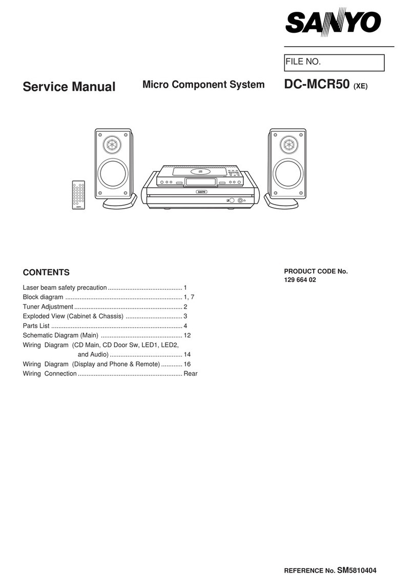
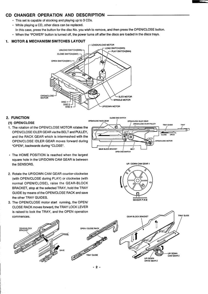
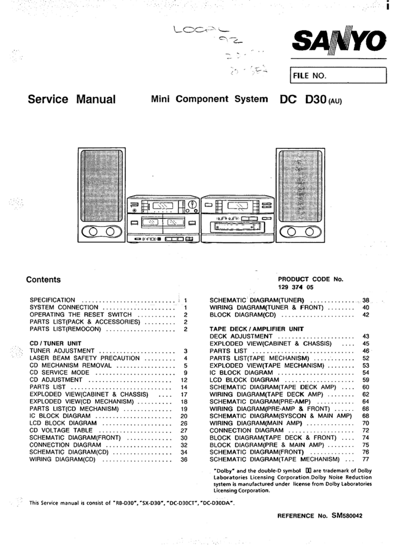
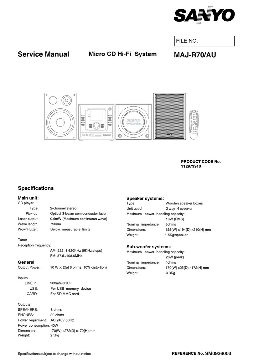
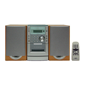
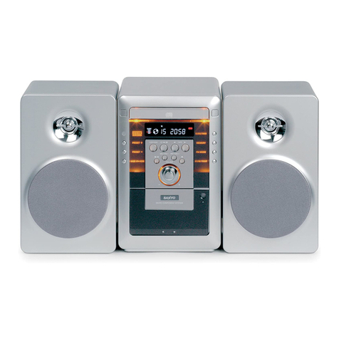
Sanyo DC-F320 User manual

Service Manual
FILE NO.
Mini Component System
DC-F320
(UK)
(W
CONTENTS
SPECIFICATION......................................................................
1
WHAT TO DO IF.......................................................................
1
LASERBEAMSAFETYPRECAUTIONS
................................
2
REMOVAL
&
INSTALLATION.................................................
2
TUNERADJUSTMENT
............................................................
4
CDCHANGER
OPERATIONDESCRIPTION..........................
5
CD
CHANGERREPLACEMENT
.............................................
7
CD
MECHANISMADJUSTMENT
............................................
9
CD PLAYER ADJUSTMENTS
...............................................
11
TAPEDECKADJUSTMENTS
...............................................
13
EXPLODED
VIEW(CABINET
&1
CHASSIS)
..........................
15
r_:-_------__-__-____-_~
I
This serwce manual consists of “DGF320U (Main unit),
I
“RB-F320”(Remote control) and “SX-F320RUXE
,
I
LSX-F321
R,UUK”(FrontSpeaker system)
.
I
-_----------B----w
J
WEI
PRODUCT CODE No.
129 547
Ol(UK)
129 547 02(XE)
PARTSLIST
. . . . . . . . . . . . . . . . . . . . . . . . . . . . . . . . . . . . . . . . . . . . . . . . . . . . . . . . . . . . . . . . . . . . . . . . . . .
17
EXPLODEDVIEW(TAPEMECHANISM)
. . . . . . . . . . . . . . . . . . . . . . . . . . . . . .
23
EXPLODED VIEW (CD CHANGER
&
BASE MECHANISM). 24
EXPLODED VIEW (CD CHANGER MECHANISM)
.,.a,....,.....
25
IC
BLOCKDIAGRAM
&
DESCRIPTION
. . . . . . . . . . . . . . . . . . . . . . . . . . . . . . .
28
IC
&
TRANSISTOR
VOLTAGES . . . . . . . . . . . . . . . . . . ..a.......................
34
WIRINGCONNECTION
. . . . . . . . . . . . . . . . . . . . . . . . . . . . . . . . . . . . . . . . . . . . . . . . . . . . . . . . . .
36
SCHEMATICDIAGRAM
. . . . . . . . . . . . . . . . . . . . . . . . . . . . . . . . . . . . . . . . . . . . . . . . . . . . . . . . .
37
WIRINGDIAGRAM
. . . . . . . . . . . . . . . . . . . . . . . . . . . . . . . . . . . . . . . . . . . . . . . . . . . . . . . . . . . . . . . . .
47
CABLECONNECTION
. . . . . . . . . . . . . . . . . . . . . . . . . . . . . . . . . . . . . . . . . . . . . . . . . . . . . . . . . . .
55
REFERENCE No.
SM580903

SPECIFICATIONS
Note:
The below mentioned specifications are mainly based on the IHF measurements standard. They can therefore not directly be
compared with specifications based on the DIN standard or other standards.
Tuner section
L%.
:
:
:
:
:
:
:
:
:
:
:
:
:
:
:
:
:
:
:
:
:
:
:
:
:
:
:
:
:
:
:
:
:
:
LW
...................................
CD changer section
Type
.................................
Channels..........................
Sampling frequency
.........
Pick-up
.............................
Laser output.....................
Wavelength
.....................
Frequency response
........
Wow and flutter................
Cassette deck section
Track system:..................
Frequency response
........
Signal-to-noise
ratio.........
Wow and
flutter................
Fast forward and
rewind time......................
Amplifier section
Output
power..................
Inputs
VIDEO/DVD
.....................
MULTIMEDIA
IN
..............
outputs:...........................
87.5 MHz
-
108 MHz
522
kHz
-
1611
kHz
144
-
288
kHz
Changer,
3-disc
2-channel stereo
44.1
kHz
Optical
3-beam
semiconductor laser
O.GmW(Continuous
wave max.)
790 nm
20 Hz to 20
kHz
Below measurable limits
4-track, 2-channel stereo
50 Hz to 14kHz
52
dB
0.12% (WRMS)
Approx. 110 sec. (C-60)
55 W x 2 (at
6ohms,
10% distortion)
400
mVI50
kohm
400mV/50 kohm
SPEAKERS
:6
ohm
PHONES
:8
-
32 ohm
SUB WOOFER
:I0
kohm
Speaker systems
FRONT SPEAKER SYSTEM(SX-F430)
Type . . . . . . . . . . . . . . . . . . . . . . . . . . . . . . . . .
3
wa
Y
bass reflex
Unit
used . . . . . . . . . . . . . . . . . . . . . . . . . .
Woo
er
:
16 cm cone type (UK)
Woofer
:
13 cm cone type (XE)
Midrange
:
5
cm cone type
Tweeter
:
piezoelectric
Maximum power-handling
capacity . . . . . . . . . . . . . . . . . . . . . . . . . . . .
100 Watts(peak)(UK)
120 Watts (peak) (XE)
Nominal impedance . . . . . . . . .
6 ohms
Dimensions (W x H x D) . 240 x 330 x 270 (mm) (UK)
220 x 330 x 230 (mm) (XE)
Weight . . . . . . . . . . . . . . . . . . . . . . . . . . . . . .
3.9
kg
(UK)
3.5 kg (XE)
General
Power requirements . . . . . . . . .
230 V AC, 50 Hz
Power consumption . . . . . . . . .
105 Watts
Dimensions (W x H x D) .
270(W)
x 330(H) x 290(D) (mm)
Weight . . . . . . . . . . . . . . . . . . . . . . . . . . . . . .
7.5
kg
Specifications subject to change without notice.
To achieve the best sound performance, select music sources which have
the 001
DOW
SURROUND]~
mark.
Manufactured under license from Dolby Laboratories Licensing
Corporation.
DOLBY, the double-D symbol
00
and “PRO LOGIC” are trademarks of
Dolby Laboratories Licensing Corporation.
WHAT TO DO IF
lIf the operation of the unit or display is not normaLor you
wish to clear the contents of the memory.
1. Disconnect the power cord’s plug from the electrical outlet.
2. Press the RESET button for at least 20 second.
3. Connect the power cord.
4. Press the POWER button to turn the power on.
-l-
LASER BEAM SAFETY PRECAUTION
lPick-up that emits a laser beam is used in this CD player section.
Do not look directry at the laser beam coming from the pick-up
or allow it to strike against your fingers, skin, etc.
Structural Safety Interlock
This model has a disc chuck lever and top lid. This disc check
lever and top lid prevent to expose the laser beam for users.
RADIATION EXPOSURE TO BEAM IS DANGEROUS CLASS 1 LASER PRODUCT
OUTPUT POWER : 0.6
mW
MAX WAVELENGTH : 790 nm
CAUTION-INVISIBLE LASER RADIATION WHEN OPEN AND
INTERLOCKS DEFEATED. AVOID EXPOSURE TO BEAM.
ADVARSEL
-
USYNLIG LASER
STRALING
VED
ABNING,
NAR
SIKKERHEDSAFBRYDERE ER UDE AF FUNKTION, UNDGA UDS
Ri7ELSE
FOR
STRALING.
(XE)
VARNING
-
OSYNLIG LASER
STRALNING
NAR
DENNA
DEL
AR ~PPNAD
-
OCH SPiiRR iiR URKOPPLAD.
STRALEN
iiR FARLIG.
VORSICHT-
UNSICHTBARE IASERSTRAHLUNG
TRlll
AUS,
WENN
DECKEL GEbFFNET UND WENN SICHERHEITSVERRIEGELUNG
ijBERBRijCKT
IST.
NIGHT,
DEM STRAHL AUSSETZEN.
VARO
-
AVAllAESSA
JA SUOJALUKITUS
OHITEllAESSA
OLET ALTTIINA
Nb;KYMjiTTijMp;LLE LASERSATEILYLLE.
AL!+
KATSO SjiTEESEEN.
-B
o(E)
REMOVAL
&
INSTALLATION
l
Press
the
“POWER” button and check that the STANDBY LED lights.
lDisconnect the power cord’s plug from the electrical outlet.
lAll wiring should be returned to the original position after work is completed.
lFirst have ready may the new FIXERS(614 129 2496) for replaced.
lArrange the lead wires so that they are not near the heat sink.
0
\
1. CABINET ASSEMBLY
1. Remove the rear section mounting screws and side section
mounting screws.(O)
2. Remove the CABINET ASSEMBLY in the direction of arrow.
(0)
2. CD MECHANISM BLOCK
1. Remove the CD MECHANISM mounting screws.(@)
2. Remove the ANTENNA TERMINAL mounting screw.(@)
3. Remove the CD BACK PANEL mounting screws.(@)
4. Remove the rear panel lock and CD
P.W.board.(@,@)
-2-

REMOVAL
&
INSTALLATION
3. FRONT PANEL BLOCK
1. Remove the FRONT PANEL mounting screws.(@)
2. Remove the claw of PRE-AMPLIFIER
P.W.Board.(@)
FRONT
P.W.BOARD
5. PRE-AMPLIFIER
&
POWER P.W.BOARDS 6. POWER TRANSFORMER
1.
Remove the REAR-SOCKET mounting screws.(O)
1.
Remove the POWER TRANSFORMER mounting screws.
2. Remove the POWER
P.W.board.l@)l
(0)
7. TAPE MECHANISM BLOCK
1. Open the CASSETTE
LIDS.(@)
2. Remove the TAPE MECHANISM mounting screws.(@)
4. CD MECHANISM
1. Remove the CD MECHANISM mounting screws.(O)
2. Remove the POWER TRANSFORMER.(@)
8. WIRING LAYOUT
.
Arrange the lead wires so that they are not near the
heat sink of the POEWR P.W.board.
TUNEWAMP
F?W.BOARD,
lo
CD P.W.BOARD
f?N
I\
\
FRONT
F?W.BOARD
FIXER
PW.BOARD FIX

TUNER ADJUSTMENTS
Use a plastic screw driver for adjustments.
MODE : STEREO
Speaker impedance
:
6 ohm
TUNING
FM
:
87.5
-
108.0MHz
(50kHz step)
MW
:
522
-
1611 KHz
(9kHz
step)
LW
:
144
-
288KHz
(9kHz
step)
FM ANT._
750hm
(E)
AM LOOP
ANT.
c
(H)
l.FM
Step
1
2
+
J2005
TP12(E)
L2154 L2153
CT251 CT252
@I@
TP27(
E)
/
R2325
0
o/R2326
I‘\
TP25(L-CH)
TP26(R-CH)
SG RF Level
:
75 open Voltage
dBpV
Antenna
:
75 unbalanced
,
Modulation
:
1
kHz
Dev.
:
f22,5kHz(MONO) +22.5KHz(STEREO)
f6.75KHz(PILOT)
Adjusting
Connection
SG
Set
Adjustment
Remark
Circuit
Input Output
Frequency Position
Cover _.- Connect Digital DC voltmeter to
67.5MHZ
Low ---
more than 0.9 V
Vhge
___
TPIl(H),
TP12(E). 1
OB.OMHZ
High
___
less
than
9.OV
Tracking Connect FM SG to FM Antenna Connect to
VlVM
9O.OMHZ
Low ---
Max.
(SG=6dB
/IV)
TP25(L)
or
TP26(R),
TP27(E)
106.OMHZ
High
___
SG Modulation
:
1
kHz,
30%
Antenna, IRE Loop, Distance
:
60 cm
2.MW
Step
Adjusting Connection
SG
Set
Adjustment
Remark
Circuit
Input Output
Frequency Position
1
Cover
___
Connect Digital DC voltmeter to 522kHZ Low
L2153
vt
= 1
.OVfO.O5V
Voltage
___
TPll(H),
TP12(E).
16llkHZ High ---
less than
9.OV
2
Tracking Conned AM SG to
Connect to VTVM 603KHZ Low I2152 Max.
Test loop
Ant.(SG=8CdB
pv)
TP25(L)
or
TP26(R),
TP27(E). 1404kHZ
High
CT252
3.LW
Step
Adjusting
Connection
SG
Set
Adjustment
Remark
Circuit
Input
output Frequency Position
1
Cover
___
Connect Digital DC voltmeter to 144kHZ
Low
L2154 vt
=
I
sv
+o.o5v
Voitage
___
TPI
l(H),
TP12(E).
26%kHZ
High ---
less than
9.OV
2Tracking
Connect
AM SG to
Connect to VlVM
162KHZ Low l2151 Max.
Test loop
Ant.(SG=8OdB
/IV)
TP25(L)
or
TP26(R),
TP27(E). 279kHZ High
CT251
-4-

CD CHANGER OPERATION DESCRIPTION
1.
9
This set is capable of stocking and playing up to 3 CDs.
l While playing a CD, other discs can be replaced.
In this case, press the button for the disc No. you wish to remove, and then press the OPEN/CLOSE button.
l When the “POWER” button is turned off, the power turns off after the discs are loaded in the discs trays.
MOTOR
&
MECHANISM SWITCHES LAYOUT
r
Lcm3IUNLam
MOTOR
2. FUNCTION
(l)OPEN/CLOSE
1. The rotation of the OPEN/CLOSE MOTOR rotates the
OPEN/CLOSE IDLER GEAR via the BELT and PULLEY,
and the RACK GEAR which is intermeshed with the OPEN/
CLOSE IDLER GEAR moves forward during “OPEN”,
backwards during “CLOSE”.
l The HOME POSITION is reached when the largest square
hole in the UP/DOWN CAM GEAR is between the
SENSORS.
2. Rotate the UP/DOWN CAM GEAR counter-clockwise (with
OPEN/CLOSE during PLAY) or clockwise (with normal
OPEN/CLOSE), raise the GEAR-BLOCK BRACKET, stop
at the selected TRAY, hold the TRAY GUIDE by means of
the OPEN/CLOSE RACK and save the other TRAY
GUIDES.
3. The OPEN/CLOSE motor start running, the OPEN/CLOSE
RACK moves forward, the TRAY LOCK LEVER is raised to
lock the TRAY, and the OPEN operation commences.
Y
SLIDE
CAM GEAR 2
DRIVE GEAR 2

CD CAHNGER OPERATION DESCRIPTION
4. When the TRAY closes and it reaches the tip of RIB part of
LEFT TRAY GUIDE, the LOCK LEVER is lowered to release
the TRAY, and loading proceeds.
TRAY GUIDE HOLDER
LOCK LEVER
I
OPEN
-
CLOSE
(2)LOADING
TRAY LOCK
TRAYRELEASE
1. The rotation of the LOAD/UNLOAD MOTOR rotates the
LOAD/UNLOAD DRIVE GEAR in the clockwise direction.
2. The DRIVE GEAR and the gear portion of the TRAY
meshtogether and the TRAY movers backward.
3. The completion of TRAY movement causes the UP/DOWN
MOTOR to operate and lower the TRAY HOLDER putting
the until to chucking status.
4. The rotation of the UP/DOWN MOTOR rotates the UP/
DOWN GEAR in the counter-clockwise direction. In
connection with this, the TRAY HOLDER SLIDE moves
forward, and at the same time, the RIGHT SLIDE is moved
backwards by the SYNCHRO LEVER.
TRAY HOLDER
SYNCRb
LEVER
LOAD/UNLOAD DRIVE GEAR
A
dl
LOAD/UNLOAD CAM GEAR
LOAD/UNLOAD MOTOR
UNLOAD IDLER
1
ILOADIUNLOAD
DRIVE GEAR
UP/DOWN CAM GEAR 1
UP/DOWN IDLER 2
UP/DOWN DRIVE
GEAR,1
/
Uq/DOWN IDLER 1
A” HOLDER SLIDE
LEFT SIDE
SRAC
TRAY HOLDER
UP/DOWN
DRIVE FEAR 1
/
UP/DO’iN
\
I
CAM GEAR 1
$-&‘-T
_
UP/DOWN
UP/DOWN IDLER 1
R,G”T
SLIDE BRACKET
UP/DOWN
DRIVE GEAR 2
\‘UP/DOWN
IDLER 2
DOWN MOTOR
MOTOR
UP/DOWN
CAM GEAR 2
-6-

CD CHANGER REPLACEMENT
1. LOAD/UNLOAD FUNCTION
1. Remove the 6TOP ENCOURAGE.
2. Remove the CD MECHANISM.
2.
HOW TO REMOVE THE TRAYS
1.
Remove the CHUCK BRACKET.(
@-
E)
~UP/DOWN
CAM
GEAR
2. Rotate the UP/DOWN CAM GEAR and position the collar
part of the TRAY HOLDER visible from the RIGHT SLIDE
at the midpoint between the CHUCKING and TRAY.
RIGHT SIDE
DISC STOPPER
SRAyKET
RIGHT SLIDE
I
l-
\-
TRAY 3 CHUCKING
3. REPLACING THE TRAY GUIDE
l
Have the LEFT TRAY GUIDE HOLDER and TRAY GUIDE
ready before proceeding.
1. Turn the UP/DOWN CAM GEAR and remove the setscrew
of the TRAY HOLDER from the hole in the GEAR BLOCK
BRACKET.
2. Turn the UP/DOWN CAM GEAR counter-clockwise as far
as it will go, and remove the SCREWS.
3.
4.
Remove the five setscrews of the LEFT TRAY
GUIDEHOLDER, and remove it in the direction of the arrow.
When assembling the parts, align the TRAY SLIDE and UP/
DOWN DRIVE GEAR.
RAGE
CD MECHANISM
3. Remove the three TRAYS through the gap at the back.
TRAY,ASSY
“PlDOWN CAM GEAR
I
UP/DOWN
DRIVE GEAR
-7-

CD CHANGER REPLACEMENT
4. LEFT SLIDE BRACKET
5.
UP/DOWN CAM GEAR
6. SETTING UP THE LOAD/UNLOAD GEAR
dl
LOAD/UNLOAD CAM GEAR
7.
LOAD/UNLOAD MOTOR
AD/UNLOAD IDLER 1
DNNLOAD IDLER 2
LLOAD/UNLOAD
DRIVE GEAR
SETTING UP THE TRAY SLIDE AND UP/DOWN
DRIVE GEAR 2
1.
Slide the TRAY SLIDE forward until it goes no further.
2. Align the round mark on the UP/DOWN DRIVE GEAR
2. with the mark area on the TRAY SLIDE, and install.
3. Align the shorter flat part of the UP/DOWN CAM GEAR
2, and install.
l
Set the parts in such a way that the round marks on
the two GEARS are horizontal.
8.
8
LOAD/UNLOAD
---
-I
OF THE LUBRICATION
---
J
c----------------
Note:
1
EM-50L . . . . . . . . . . . . . . . . . . . . . . . . . . . . . . .
MOLYKOTE,
EMdOL
I
SG-7 . . . . . . . . . . . . . . . . . . . . . . . . . . . . . . . . . . .
SAN
GREASE, SG-7
I
G-474B . . . . . . . . . . . . . . . . . . . . . . . . . . . . . . .
FLOIL
OIL, G-4748
I
_-_-_-_--_-_-_-_-__--_--_J
9. TRAY HOLDER
UP/DOWN DRIVE GEAR 2
LONG
CAM GEAR 2

CDCHANGERREPLACEMENT
10. SETTING UP THE TRAY HOLDER AND UP/DOWN DRIVE GEAR UP/DOWN DRIVE GEAR
1
-
1.
2.
3.
4.
5.
6.
7.
Loosen and install the SET SCREW of the SENSOR P.W.B.
Slide the TRAY HOLDER SLIDE forward until it goes no
further.
Align the round mark on the UP/DOWN DRIVE GEAR 1
with the mark area on the TRAY HOLDER SLIDE, and install.
Secure the screw.
As shown in the figure, place the UP/DOWN DRIVE GEAR
2 and UP/DOWN CAM GEAR 2
insuch
a way that they are
horizontal.
UP/DOWN CAM GEAR 2
lSet the parts in such a way that the round marks on the two
GEARS are horizontal.
Align with the triangular mark through the hole through which
the UP/DOWN CAM GEAR 2 teeth are visible.
Secure the SCREW of the SENSOR and GEAR.
Q
I
MARK
11. TRAY HOLDER SLIDE
UP/DOWN MOTOR
ASSY-
UP/DOWN DRIVE GEAR 2
10.5mm
r”ll
-f-
I
J
(6142670440)
-----------_-_-_
t;zoL
1
MOLYKOTE, EM-SOL
I
I
SG-7
SAN GREASE, SG-7
I
I
G-4748 FLOIL OIL, G-4748
I
L
-----_---_-_-_-_
_J
CD MECHANISM ADJUSTMENTS
1.
REPLACEMENT AND LUBRICATION OF THE CD MECHANISM
p”
i
@&TURNTABLE
2. CD BASE MECHANISM
SPINDLE MOTOR
SLED RETARD GEAR
l-
SLED RETARD GEAR 2 PICK RACK GEAR
MOTOR BLIMIT SW P.W.B
SLED

CD MECHANISM ADJUSTMENTS
3. CD MECHANISM
(1)Replacement of the spindle motor
.
.
1.
2.
3.
4.
5.
6.
7.
8.
First, prepare the new turntable and new special washer for
replacement. The removed turntable will be deformed by
the heat of the soldering iron, and cannot be reused.
Prepare dial-type calipers.
The attached bonding material can be dissolved by using a
60W soldering iron to heat the shaft the upper part of the
turntable for about one minute.
The turntable can then be removed from the shaft by
verycarefully applying force upward at the center of the lower
surface of the turntable.
Remove the two screws and remove the spindle motor.
Attach the special washer top the spindle motor.
Clean the spindle motor’s shaft. To clean them, use a soft
cloth soaked in isopropyl alcohol.
Apply a small amount of a mixture of the
”
Three bond
2001 “and “2015F” bonding materials to the motor’s shaft.
Install the turntable as shown in the figure.
Secure the turntable by pressing gently. Be sure to wipe
away (by using a piece of cloth, or similarmaterial) any
bonding material coming out of the hole.
(2)Replacing the pick-up
1.
2.
3.
4.
5.
Insert the pick-up rail into the base chassis.
If the rack of the base chassis are missing when the pick-up
rail have been installed, first wipe the tips of the rail with
alcohol.
After the pick-up has been replaced, apply grease (FLOIL
G-4748) to the
sections.
The pick-up P.W.Board pattern’is “shorted”, as shown in
the figure, so that the new pick-up will not be susceptible to
the effects of static.
34.9
f
0.1 mm
--TURNTABLE
SPINDLE MOTOR
SLED MOTOR
PICKUP RACK GEAR
Set the pattern to “open” after the pick-up has been
replaced.
(BE SURE AT THIS TIME, NOT TO TOUCH ANY OTHER PART.)
@I/--
O-
(SHORT) (OPEN)

CD PLAYER ADJUSTMENTS
1.
PREPARATION 2. INlTlALlZATlON OF
VR101
Measuring instruments, tools and filter
1,
Test disc.
:
YEDS 18 (SONY) or etc.
2. Oscilloscope
:
SS571
l(1
OMHz
or dual-phenomenon) or
Memoryscope
:
DSS6521 (Storagescope)
3. Screwdrivers(non-metallic) for adjustments
3. PARTS LOCATION
VI31
01
lnitialization position
TP1/(RF)
m
VRlOi
7
TRACKING
BALANCE
TRACKING
CNlOl BALANCE
EST POINT
(+)
EYE PATTERN
CD PICK UP MAINTENANCE
About pick-up (Optical lens) Cleaning
Clean the lens with the specified cleaning disc or moisten a cotton swab with isopropyl alcohol and cleaning paper.
Specified cleaning disc
:
LC-1 (Part code
:
645 026
1961 . . . . . manufactured by SANYO.)
Regarding procedure of cleaning with moisten cotton swab, please refer to the attached as follows.
7.
Cotton swab wrapped with Cleaning paper
2. Add the isopropyl alcohol
3.
Gently move the tip of cotton swab just like a draw a whirpool from inside to outside on the surface of lens.
-
11
-

CD PLAYER ADJUSTMENTS
4. ADJUSTMENTS
Adjustment
Item
(a) Tracking
balance
(b) Checking
the “eye”
pattern
Measuring
instrument
Oscilloscope
Oscilloscope
Service
mode output
connection
TP3
:
TE
TR4
:
VC
TPI
:
RF
TP4
:
VC
Adjustment
location
VR101
(1)Tracking balance adjustment
1. Connect an Oscilloscope to TP3 (TE) and
TP4(VC).
2. Turn “POWER” switch on.
3. Set the test disc.(DISC 1)
4. Press “SOUND PRESET” key and “TUNING MODE” key
simultaneously
.Within
1 second after pressing the
“MEMORY” switch.
(SERVICE MODE
:
Tracking balance adjustment mode)
5. Confirm that the oscilloscope waveform is symmetrical on
the top and bottom in relation to
OV(VC).
6. If it cannot be adjusted by fully rotating
VRlOl,
cut the
resistor R1108 (1 Ok
R
)
with a pair of
pliers,and
adjust
again.
7. To cancel service mode, disconnect the power cord’s plug
from the electrical outlet.
(2)Checking the “eye” pattern
1. Switch “ON” the POWER.
2. Connect an oscilloscope to
TPl
(RF) and
TP4(VC).
3. Load the test disc.
4. “PLAY/PAUSE” switch push ON.
5. Check to be sure that the “eye” pattern is at the center
ofwaveform and that the diamond shape is clearly defined.
6. Press the “STOP” button.
7. Switch “OFF” the POWER.
Adjustment value
Waveform symmetry
A=B
Check be sure that the “eye”
pattern is at the center of the
waveform and that the diamond
shape is clearly defined
TE
200mVIdiv.
5ms/div.
ENING
EXPANDED
-12
-

TAPE DECK ADJUSTMENTS
Adjustment Item Test Tape Measuring Srevice Mode Adjust Adjust
Instrument location value
(1) HEAD AZIMUTH
VI-r-738 AC-voltmeter
HEAD AZIMUTH Max.
-
TAPE “A”
(1
OKHz)
SCREW
(FWD/REV)
(2) HEAD AZIMUTH V-IT-738
AC-voltmeter
HEAD AZIMUTH Max.
_
TAPE
“B” (1
OKHz)
SCREW
I
1.
HEAD REPLACEMENT AND AZIMUTH ADJUSTMENT
(l)Head replacement
After replacement, demagnetize the heads by using a
degausser.
Be sure to clean the heads before attempting to make any
adjustments.
Be sure both channels (1 and 2) are the same level (Using
a dual-channels oscilloscope).
All wiring should be returned to the original position after
work is completed.
(2)Head azimuth
TAPE “A”
.
1.
2.
3.
4.
.
1.
2.
3.
4.
TAPE
“B”
Load a test tape for azimuth adjustment.
Press the PLAY button.
Azimuth screw adjustment.
Press the STOP button.
L
Load a test tape (VTT-738,
etc.:lOKHz)
for azimuth
adjustment.
Press the PLAY button.
Use a flat-tip (-) screwdriver to turn the screw for normal
azimuth adjustment so that the left and right outputs are
maximized at the same phase during normal playback.
Press the STOP button.
TAPE “A”
TAPE
“B”
PLAY HEAD
I
R/PHEAD
-,
E. HEAD
----
--___-
---_----
1
lAfter making the adjustment, secure the azimuth
-
lb
-
adjustment screw by applying screw lock (TB-1401 B).
I
~
----
---__-
----
----

TAPE DECK ADJUSTMENTS
(3)Motor speed
NORMAL SPEED
1. Insert the test tape (MTT-111 N) into Tape “A” or “B”.
2. Align to 3020
f
1
OHz
by
VR311.
3.Confirm
2980
f
40Hz
at this condition.
(4)BiAS
Alignment
Adjust
L,R
output to 700mV by
VFi374,384
which activating
BIAS circuit.
TAPE OUTPUT
TESTPOINT
CN373
BIAS-ADJUSTMENT
w
c
TAPE SPEED
UI!
L-CH
VR374
ADJUST;;3!;
a
ui
BIAS-ADJUSTMENT BIAS-FREQUENCY
R-CH
@I
ADJUSTMENT
VR384
L3601
2. CHECKING THE MECHANISM TORQUES
1. Clean the head, capstan and pinch roller before making any measurement.
2. Check the both normal and reverse playback.
Measureent Take-up torque
Cassette
for PLAY
:
TW-211
lA(FWD)
measurement
FSWDIREW
:
TW-2231
PLAY
25
-
63gr.cm
F.FWD/REW
60
-
120ar.cm
Back tension
PLAY
:
TW-211 lA(FWD)
2.0
-
5.0gr.cm
Tape tension
Drive-power cassette
TW-2412(FWD)
70 gr or more
-14
-

EXPLODED VIEW (CHASSIS)
YOl
I
ii
I’
yo2-v
8
yo2-m
l!l!l
I i
I
YO8-&J
92-
Y18
I
Y18
Y18
Y17

EXPLODED VIEW (CABINET)
-
16
-

PARTS LIST
PRODUCT SAFETY NOTICE
EACH PRECAUTION IN THIS MANUAL SHOULD BE FOLLOWED DURING SERVICING. COMPONENTS IDENTIFIED WITH THE IEC
SYMBOL
/I
IN THE PARTS LIST AND THE SCHEMATIC DIAGRAM DESIGNATED COMPONENTS IN WHICH SAFETY CAN BE OF
SPECIAL SIGNIFICANCE. WHEN REPLACING A COMPONENT IDENTIFIED BY A, USE ONLY THE REPLACEMENT PARTS DESIGNATED,
OR PARTS WITH THE SAME RATINGS OF RESISTANCE,
WATTAGE
OR VOLTAGE THAT ARE DESIGNATED IN THE PARTS LIST
IN THIS MANUAL. LEAKAGE-CURRENT OR RESISTANCE MEASUREMENTS MUST BE MADE TO DETERMINE THAT EXPOSED
PARTS ARE ACCEPTABLY INSULATED FROM THE SUPPLY CIRCUIT BEFORE RETURNING THE PRODUCT TO THE CUSTOMER. J
CAUTION :
Regular type resistors and capacitors are not listed. To know those values, refer to the schematic diagram.
Regular type resistors are less than
l/4
W carbon type and 0 ohm chip resistors.
Regular type capacitors are less than 50 V and less than 1000
pF
type of Ceramic type and Electrical type.
N.S.P
:
Not available as service parts.
PACKING
&
ACCESSORY
REF.NO.
PART NO.
DESCRIPTION
6141762302 INNER POLYE
COVER,AC
CORD(UK)
6142980668 CARTON
CASE(XE)
6142964071
CUSHION,BOTTOM
6142964088
CUSHION,TOP,TOP(XE)
614 269 0949
CUSHION,SET(UK)
614 271 6656
CUSHION,SET(XE)
6142965856
INSTRUCTlON,MANUAL(UK)
6142980675 lNSTRUCTlON,MANUAL(XE)
6450136535 POLY BAG-0250X0350,
INST
MANUAL(XE)
6450122958 POLY BAG-0250X0350,
INST
MANUAL(UK)
6450051227 ASSY,ANTENA,LOOP,AM LOOP ANT
6142294635
ANT,FM ANT
6450277214
REMOCON,RB-F320,REMOCON
6450269424
BATTERY COVER
CABINET
&
CHASSIS
REF.NO.
PART NO.
1
6142895443
2
6142965207
3
6141291901
or
614 284 1884
4
614 298 0637
4
614 299 0612
5
6141299136
6
614 291 8050
7
614 296 5757
8
6142661918
9
6142976920
10
6142921364
11
6142896211
21
614 296 5184
23
6142963807
24
6142963814
25
6142657898
26
6142657904
27 6142907429
28
6142907436
29
6142965481
30
614 297 2410
31
6142972427
32
614 270 8316
33 6142963852
34
6142965153
36
614 290 7412
37
6142963821
38
6142963685
39
6142963708
DESCRIPTION
ASSY,CABINET,BOTTOM
MOUNTING,PWB,SIDE PWB FIX
FIXER,AC
CORD
FIXER,AC
CORD
PANEL,REAR,AMP
(XE)
PANEL,REAR,AMP
(UK)
LUG,PICK
LEAD
CD MECHA PICK COVER
PANEL,REAR,CD
REAR
JOINT,CD-MECHA
FORCEMENT
ASSY,CABINET,BENDING,
AFTER BENDING
TERMINAL,CD,CD MECHA EARTH
TERMINAL,ANT,PANEL,REAR
DEC,WINDOW
CASSETTE,CASSElTE
COVER,CASSETTE L
COVER,CASSE-fTE
R
ASSY,LID,CASSETTE,DECK
L
ASSY,LID,CASSETTE,DECK
R
SPRING,WIRE,CASSETTE,
CASSETTE L
SPRING,WIRE,CASSETTE,
CASSETTE
R
ASSY,CABINET,FRONT
KNOB,ROTARY,VOLUME JOG
ASSY,GEAR,CASSETTE
DEC,WINDOW
FL
ASSY,PANEL,FRONT
FL
SPRING,TENS,CD DOOR
CD DOOR
BUlTON,POWER
BUlTON,FUNCTlON,FUNCTlON(l) -17
-
REF.NO.
40
41
42
43
44
45
46
47
48
49
50
PART NO. DESCRIPTION
614 296 3715
BUl-TON,FUNCTlON,FUNCTlON(2)
614 296 3746 BUTTON,TUNER
614 296 3760
BUTTONSOUND
614 296
3753 BUl-fON,MEMORY
614 296
3739 BUlTON,CASSETTE,DECK MODE
614 296 5160 BUTTON,COMP REC
614 296 3722
BUi-i-ON,CD PLAY/STOP
614 296 3692 BUTTON,DISC
SEL,DISC
SEL
614 296 3920 REFLECTOR,SOUND,LIVE
ETC
614 289 1117 MOUNTING,BRACKET,
DECK MECHA BOTTOM
614 289
1100 MOUNTING,BRACKET,
DECK MECHA TOP
FIXING PARTS
REF.NO.
PART NO. DESCRIPTION
YOl
411 021 3701
SCR S-TPG BIN
3X1
O,BOTTOM-REAR
YO2 411
028 2905 SCR S-TPG
PAN
2X4,
YO3
411 021 3503
YO4
YO5
411 021 3503
411 020 9902
Y06 411 021 3503
YO7
411 001 4407
Y08 411 021 3701
YO9
411 021 3701
YlO 411 021 3503
Yll
Y13
Y14
Y15
411 001 3905
411 021 3503
411 021 3503
411 021 3503
Y16 411 020 9506
Y17
411 021 3701
Y18 411 021 3701
Y31
411 021 3503
Y33
411 021 3503
Y34
Y35
411 024 3708
411 021 3503
CD MECHA-JOINT
SCR S-TPG BIN 3X10.
CD MECHA-FRONT
SCR S-TPG BIN BXlO,TERMINAL CD
SCR S-TPG BRZ+FLG
3X8,
CD MECHA-CD PWB
SCR S-TPG BIN 3X10,
CD MECHA-PICK COVER
SCR S-TPG PAN 3X6,
CD MECHA-PICK COVER
SCR S-TPG BIN 3X10,
CD MECHA-REAR
SCR S-TPG BIN 3X10,
REAR-ELECT PARTS
SCR S-TPG BIN
3X10,
BOTTOM-FRONT FIX
SCR S-TPG BIN 4X6,TRANS FIX
SCR S-TPG BIN 3XlO.SIDE PWB FIX
SCR S-TPG BIN 3XlO.TR HOLDER FIX
SCR S-TPG BIN 3X10,
HEAT SINK-BOTTOM
SCR S-TPG BRZ+FLG
3X16,POWER
IC
SCR S-TPG BIN 3Xl0,CABINET
SCR S-TPG BIN BXlO,REAR-REAR
SCR S-TPG BIN 3X10,FRONT PWB FIX
SCR S-TPG BIN 3X10,
PANEL-BUTTON FIX
SCR S-TPG PAN+FLG
2X6,
DECK MECHA-MOUNTING PWB
SCR S-TPG BIN
3X1
0,
DECK MECHA FIX

PARTS LIST
SPEAKER ASSY.
REF.NO.
PART NO.
614 297 8382
6142978399
614 299 0810
614 299 0940
6450252990
6450284779
ELECTRIC-PART
REF.NO.
PART NO.
6142922873
6142983928
71
A6450274602
72
A4230056509
73
6142978559
74
6142916568
75
A6450089732
or
A6450057120
75
A645 016 9939
or
A6140233148
or
A6142552513
76
A6450251405
77
6450285493
78
6450285509
DESCRIPTION
ASSY,BOX,SPEAKER
LEFT(XE)
ASSY,BOX,SPEAKER
RIGHT(XE)
ASSY,BOX,SPEAKER
LEFT(UK)
ASSY,BOX,SPEAKER
RIGHT(UK)
ASSY,GRILLE(UK)
ASSY,GRILLE(XE)
DESCRIPTION
ASSY,WIRE,PLAY-HEAD LEAD
ASSY,WIRE,WP
HEAD LEAD
TRANS,POWER
FUSE 250V
1.25A
ASSY,HEAT
SINK,FOR
POWER AMP
MOUNTING,PWB
CORD,POWER(UK)
CORD,POWER(UK)
CORD,POWER(XE)
POWER CORD(XE)
POWER CORD(XE)
FLEXIBLE FLAT CABLE,FRONT-CD
FLEXIBLE FLAT CABLE,
PREAMP-DECK
FLEXIBLE FLAT CABLE,FRONT-DECK
MAIN-AMPLIFIER
&
TUNER P.W.BOARD ASSY.(N.S.P)
PART NO.
DESCRIPTION
A 6142978443
ASSY,PWB,MAIN
&
TUNER(N.S.P)
4030624700 POLYESTER 5600P J 50V
4030595505 POLYESTER
0.022U
J 50V
4030595505 POLYESTER
0.022U
J 50V
4030820201 POLYPRO 470PJ
1OOV
403 082 2205 POLYPRO 560PJ
1OOV
403 106 1603
NP-ELECT 1 U
Q
50V
4032628607 DL-ELECT 0.047F Z
5.5V
4033044802 DL-ELECT 0.047F Z
5.5V
4030572407 POLYESTER 0.1 U J 50V
4031686103
MT-POLYEST 0.1 U J 50V
4031850108 MT-POLYEST
0.47U
J 50V
4030677805 MT-COMPO
0.47U
J 50V
4031849805 MT-POLYEST
0.22U
J 50V
4030676709 MT-COMPO
0.22U
J 50V
4030572407
POLYESTER 0.1 U J 50V
4030572407
POLYESTER 0.1 U J 50V
4031850108 MT-POLYEST
0.47U
J 50V
4030677805 MT-COMPO
0.47U
J 50V
403 184 9805 MT-POLYEST
0.22U
J 50V
4030676709 MT-COMPO
0.22U
J 50V
4032000403 ELECT 2200U M 50V
6142555750
TERMINAL
614 035 4942
SOCKET,DIP
5P
6142379783
SOCKET
6450090042 JACK,PHONE D6.43
6142607411
SOCKET
6450125089
SOCKET,FPC
1OP
6450054181 SOCKET,lOP
6450090189
SOCKET,20P
614 281 3669
CORD,5P CONNECTOR
6450056451
SOCKET,SPEAKER
4P,SP
6450051029
JACK,RCA
6142923207
CORD,1
P CONNECTOR
6140201253
SOCKET,GP
645 004 2317 TRIMMER,30PF
6140076356
TRIMMER
REF.NO.
D2151
02152
D2451
or
or
or
D2454
or
or
or
D2455
or
or
or
D2456
or
or
or
D2461
or
or
or
D2463
or
or
or
D2464
or
or
or
D4400
D4410
D4414
D4415
D4416
D4470
D4471
D4494
D4700
D4701
D4900
04901
D4902
D4903
D4920
D4940
D4960
D4970
IC231
lC245
IC450
IC451
lC452
lC458
lC459
IC470
lC497
or
L2151
L2152
L2153
L2154
L2301
L2451
L4700
or
L4800
or
Q2140
18
-
REF.NO.
91
coo01
coo02
coo03
coo04
C2152
C2155
C2457
C4432
or
c4705
C4706
c4750
or
c4751
or
C4805
C4806
C4850
or
C4851
r4902
c4903
CN201
CN412
iN422
CN452
CN454
EN455
CN460
CN470
CN471
CN472
CN492
CT251
CT252
PART NO.
DESCRIPTION
407091 5004 VARACTOR DI SVC321SPA-C-2
407 091 5004 VARACTOR DI SVC321SPA-C-2
4070079904
DIODE GMAOl
4070124406 DIODE 155133
4070125809 DIODE 155176
407 153 6109
DIODE 1 SS119-041
4070079904
DIODE GMAOl
4070124406
DIODE 1 SS133
4070125809 DIODE
lSS176
407 153 6109
DIODE 1
SSl19-041
4070079904
DIODE GMAOl
4070124406 DIODE
lSS133
4070125809 DIODE lSS176
407 153 6109 DIODE lSS119-041
4070079904
DIODE GMAOl
4070124406 DIODE
lSS133
4070125809
DIODE 1 SS176
407 153 6109 DIODE lSS119-041
4070079904
DIODE GMAOl
4070124406
DIODE 1 SS133
407 012 5809 DIODE
lSS176
4071536109 DIODE
lSSl19-041
4070079904
DIODE GMAOl
4070124406 DIODE
lSS133
407 012 5809
DIODE 1 SS176
4071536109 DIODE lSS119-041
4070079904
DIODE GMAOl
4070124406 DIODE
iSS133
4070125809 DIODE
lSS176
407 153 6109 DIODE lSS119-041
4070124406
DIODE 1 SS133
4070124406 DIODE
lSS133
4070124406 DIODE
lSS133
4070124406 DIODE
lSS133
A 4070049709 DIODE DSKlOC
4070639108 ZENER DIODE
MTZJ6.8B
4070124406 DIODE
lSS133
4070994603 ZENER DIODE
MTZJ3.9B
4070639108 ZENER DIODE
MTZJ6.8B
4070639108 ZENER DIODE
MTZJ6.8B
A 4071965800
DIODE 1 N5402BD82
A 4071965800
DIODE 1 N5402BD82
A 4071965800
DIODE 1 N5402BD82
A 407 196 5800
DIODE 1 N5402BD82
4070996805 ZENER DIODE
MTZJ13B
4070996805 ZENER DIODE
MTZJ13B
4070996805 ZENER DIODE
MTZJ13B
4070124406
DIODE 1 SS133
4093792705 IC LA1832ML
4093784205 IC LC72131MD
4093538709 IC BU4052BCF
4090397804 IC
NJM4558M
4090397804 IC
NJM4558M
4093443607 IC
BH3854AFS
4090397804 IC
NJM4558M
A 409 399 6905 IC
STK417-090
A 4091452809 IC NJM7805FA
A 409 396 8704
IC KIA7805PI
6142555798
TRANS,RF
6142555781
TRANS,RF
6142555767
TRANS,OSC
6142555774
TRANS,OSC
6450040580 INDUCTOR,lM J
645 001 4581 INDUCTOR,lOOU
K
614 202 1712 V.H.F COIL
6141969763
V.H.F COIL
6142021712
V.H.F
COIL
614 196 9763
V.H.F COIL
405 141 3307
TR
KTC3198-GR

PARTS LIST
REF.NO.
or
or
:2152
or
or
:2153
or
or
or
Q2154
or
or
or
Cl2155
or
or
t2156
or
or
:2157
Q2201
02310
or
or
or
Q2451
:2452
:2453
or
04400
or
or
or
:4401
or
or
or
or
Q4410
or
or
or
:4411
or
or
or
or
Q4412
or
or
or
:4431
or
or
:4432
or
or
or
or
PART NO. DESCRIPTION
405
141 3208
TR KTC3198-Y
405 020 7402
TR
2SC945A-P
405 020 7204 TR 2SC945A-K
405
141 3307 TR
KTC3198-GR
405 141 3208
TR KTC3198-Y
405
020 7402 TR 2SC945A-P
405 020 7204 TR 2SC945A-K
405
141 3307 TR
KTC3198-GR
405
141 3208
TR
KTC3198-Y
405 020 7402
TR
2SC945A-P
405
020 7204 TR 2SC945A-K
405 141 3307
TR
KTC3198-GR
405 141 3208
TR
KTC3198-Y
405 020 7402 TR 2SC945A-P
405 020 7204 TR 2SC945A-K
405
141 3307
TR
KTC3198-GR
405
141 3208
TR
KTC3198-Y
405 020 7402 TR 2SC945A-P
405 020 7204 TR 2SC945A-K
405
141 3307 TR
KTC3198-GR
405
141 3208 TR
KTC3198-Y
405
020 7402 TR 2SC945A-P
405
020 7204 TR 2SC945A-K
405 026 9004
TR
2SK222-D
405 016 0806 TR 2SC2839-E
405 141 3307
TR
KTC3198-GR
405
141 3208
TR
KTC3198-Y
405 020 7402 TR 2SC945A-P
405 020 7204 TR 2SC945A-K
405 000 0904 TR
DTAll4YS
405
036 3702 TR
2SAl564
405
000 0904 TR DTAl14YS
405
036 3702 TR
2SAl564
405
000 0904 TR
DTAll4YS
405 036 3702 TR
2SAl564
405 020 7402 TR 2SC945A-P
405 020 7204 TR 2SC945A-K
405 012 2002
TR 2SC1815-GR
405
141 3307 TR
KTC3198-GR
405 141 3208 TR
KTC3198-Y
405
020 7402 TR 2SC945A-P
405
020 7204 TR 2SC945A-K
405
012 2002
TR
2SCl815-GR
405
141 3307
TR
KTC3198-GR
405
141 3208
TR
KTC3198-Y
405 020 7402 TR 2SC945A-P
405 020 7204 TR 2SC945A-K
405 012 2002 TR 2SCl815-GR
405 141 3307 TR
KTC3198-GR
405
141 3208 TR
KTC3198-Y
405 020 7402 TR 2SC945A-P
405
020 7204 TR 2SC945A-K
405
012 2002 TR 2SCl815-GR
405 141 3307
TR
KTC3198-GR
405 141 3208
TR
KTC3198-Y
405
020 7402 TR 2SC945A-P
405 020 7204
TR
2SC945A-K
405 012 2002 TR 2SC1815-GR
405
141 3307 TR
KTC3198-GR
405
141 3208 TR
KTC3198-Y
405
141 3406 TR KTAl266-GR
405
141 3505 TR
KTAl266-Y
405 005 2002 TR 2SA733-P
405 005 1906 TR 2SA733-K
405 020 7402 TR 2SC945A-P
405 020 7204 TR 2SC945A-K
405 012 2002 TR 2SCl815-GR
405
141 3307 TR
KTC3198-GR
405
141 3208 TR
KTC3198-Y
REF.NO.
Q4433
or
or
or
z4434
or
or
or
z4435
or
or
or
:4436
or
or
or
:4470
or
or
or
Q4471
or
or
:4500
Q4501
or
Q4600
Q4601
:4700
Q4701
or
or
or
:4702
or
or
:4800
Q4920
or
or
:4921
or
or
:4940
or
:4941
or
or
or
:4960
or
or
or
:4961
or
_
,i’_
PART NO. DESCRIPTION
405 020 7402 TR 2SC945A-P
405 020 7204 TR 2SC945A-K
405 012 2002 TR 2SCl815-GR
405 141 3307 TR
KTC3198-GR
405 141 3208
TR KTC3198-Y
405 020 7402
TR 2SC945A-P
405 020 7204
TR
2SC945A-K
405 012 2002 TR 2SCl815-GR
405 141 3307 TR
KTC3198-GR
405 141 3208 TR
KTC3198-Y
405 020 7402
TR
2SC945A-P
405 020 7204 TR 2SC945A-K
405 012 2002 TR 2SCl815-GR
405 141 3307 TR
KTC3198-GR
405 141 3208 TR
KTC3198-Y
405 020 7402
TR 2SC945A-P
405 020 7204 TR 2SC945A-K
405 012 2002
TR
2SCl815-GR
405 141 3307 TR
KTC3198-GR
405 141 3208 TR
KTC3198-Y
4051413406
TRKTAl266-GR
4051413505 TRKTAl266-Y
4050052002 TR2SA733-P
4050051906
TR
2SA733-K
405 141 3406 TR KTAl266-GR
405 141 3505 TR KTAl266-Y
405 005 2002 TR 2SA733-P
405 005 1906 TR 2SA733-K
405 033 6805 TR
2SDl468SS
405 033 6805
TR
2SDl4fjSSS
405 033 6706 TR
2SDl468SR
405 033 6805
TR
2SDl468SS
405 033 6805
TR
2SDl468S-S
405 033 6706
TR
2SDl468SR
405 033 6805
TR
2SDl468SS
405 020 7402 TR 2SC945A-P
405 020 7204 TR 2SC945A-K
405 012 2002
TR
2SCl815-GR
405 141 3307 TR
KTC3198-GR
405 141 3208 TR
KTC3198-Y
405 141 3406 TR KTAl266-GR
405 141 3505 TR KTAl266-Y
405 005 2002
TR
2SA733-P
405 005 1906 TR 2SA733-K
405 033 6805 TR
2SDl468SS
405 141 3406 TR KTAl266-GR
405 141 3505 TR
KTAl266-Y
405 005 2002 TR 2SA733-P
405 005 1906 TR 2SA733-K
405 141 3406 TR KTAl266-GR
405 141 3505 TR
KTAl266-Y
405 005 2002 TR 2SA733-P
405 005 1906 TR 2SA733-K
A405 095 1602 TR 2SD2061-E
A
405 095 1701 TR 2SD2061
-F
A405 138 6403 TR KTD2058Y
405 020 7402
TR
2SC945A-P
405 020 7204
TR
2SC945A-K
405 012 2002 TR
2SC1815-GR
405 141 3307 TR
KTC3198-GR
405 141 3208 TR
KTC3198-Y
405 020 7402 TR 2SC945A-P
405 020 7204 TR 2SC945A-K
405 012 2002 TR 2SCl815-GR
405 141 3307 TR
KTC3198-GR
405 141 3208 TR
KTC3198-Y
405 020 7402
TR
2SC945A-P
405 020 7204 TR 2SC945A-K
405 012 2002 TR 2SCl815-GR
Other manuals for DC-F320
2
Table of contents
Other Sanyo Stereo System manuals

Sanyo
Sanyo DC D30 User manual

Sanyo
Sanyo DC-D7 User manual

Sanyo
Sanyo DC-DA1250M User manual

Sanyo
Sanyo DC-DA180 User manual

Sanyo
Sanyo DC-AS1600DX/XE User manual

Sanyo
Sanyo DC-007C User manual

Sanyo
Sanyo DTA-2680 User manual

Sanyo
Sanyo AWM-660 User manual

Sanyo
Sanyo DC-DA1000 User manual

Sanyo
Sanyo DC-MCR350M User manual

Sanyo
Sanyo DC-D27 User manual

Sanyo
Sanyo DC D60 User manual

Sanyo
Sanyo DC-DA2000 User manual

Sanyo
Sanyo DC-DA1400M User manual

Sanyo
Sanyo DC-F430AV User manual

Sanyo
Sanyo DC-F170 User manual

Sanyo
Sanyo DC-MX40i/AU User manual

Sanyo
Sanyo DC-DA3300M User manual

Sanyo
Sanyo DC-D9 User manual

Sanyo
Sanyo MDG-007 User manual