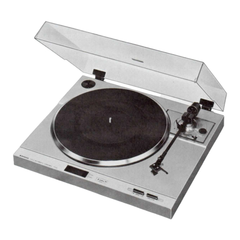
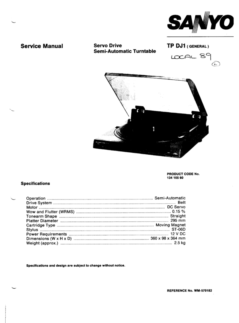
Sanyo TP 250 User manual

SERVICE
MANUAL
as
SANYO
STEREO
TURNTABLE
TP
250
SPECIFICATIONS
Motor
DC
servo
motor
Stylus
0.6
mil
diamond
stylus
No.
ATN3601
Drive
system
Belt
drive
Stylus
pressure
1.5—2.59q
Speed
33-1/3
and
45
rpm
Frequency
response
20
—
20,000
Hz
Wow
and
flutter
0.05%
WRMS
Channel
separation
20
dB
Rumble
—70
dB
Power
source
AC:
220V,
50Hz
Turntable
platter
306
mm
(12’’)
Power
consumption
3.5
W
Tone
arm
Static-balance
type
Dimensions
(Approx.)
420(W)
x
370(D)
x
126(H)
mm
Tracking
error
+1.5°
(16-9/16""
x
14-9/16"
x
5”
Overhang
15mm
Weight
(Approx.)
3.8
kg
(8
Ibs.
6
ozs.)
Cartridge
Magnetic
stereo
cartridge:
VM
type
No.
AT3601
*Specifications
and
design
are
subject
to
change
without
notice.
WM-10561

ADJUSTMENT
ADJUSTMENT
OF
HEADSHELL
:
The
headshell
attached
to
the
tonearm
should
not
be
inclined
either
to
the
right
or
to
the
left.
If
necessary,
loosen
the
two
screws
on
the
bottom
of
the
tubular
arm
and
adjust
the
headshell.
Be
sure
that
the
stylus
is
normal
to
the
record
surface.
ADJUSTMENT
OF
AUTO-RETURN
Remove
the
turntable
to
set
the
tone
arm
in
the
reset
position
(1).
Under
this
state,
move
the
gear
so
that
the
tip
of
lever
M16
intermeshes
with
the
withdrawn
part
of
cam
for
main
gear.
Besides,
lower
trip
lever
M13
and
trip
lever
M24
pushed
toward
the
arrow
marks
A
and
B,
respectively.
Turn
pipe
assy.
M6
toward
the
arrow
mark
C
to
set
so
that
the
convex
part
of
pinion
and
the
tip
of
claw
for
the
egagement
lever
M12
contact
each
other
(arrow
mark
a).
Next,
move
the
tone
arm
(toward
arrow
mark
D).
When
the
distance
between
the
center
shaft
of
turntable
and
the
needle
tip
becomes
64
thru
65
mm
(2),
insert
a
blade
screwdriver
into
part
C,
and
adjust
by
turning
it
clockwise
or
counterclockwise
so
that
the
tip
of
trip
lever
M24
begins
to
contact
with
lower
trip
lever
M13
(arrow
mark
b).
Finally
put
on
the
turntable,
and
check
the
performance
of
auto-return.
STYLUS
HEIGHT
ADJUST
'
TONE
ARM
LIFT
LEVER

ADJUSTMENT
__
ADJUSTMENT
OF
STYLUS
HEIGHT
Setting
the
record
disk
in
place,
raise
the
tonearm
lift
lever.
Bring
the
tonearm
to
above
the
disk,
and
insert
a
screw-
driver
into
the
“stylus
height
adjust’’
hole
(see
drawing
for
ADJUSTMENT
OF
AUTO-RETURN)
and
turn
it
right
or
left
until
the
distance
between
the
disk
and
stylus
becomes
8+
1mm.
RECORD
DISK
aa
——
|
fi
&8+imm
=
a
ADJUSTMENT
OF
TURNTABLE
SPEED
Setting
the
pitch
control
in
the
middie
position,
place
the
speed
select
switch
in
the
45
rpm
position.
Insert
a
screw-
driver
from
the
bottom
of
deck
pane!
and
turn
SVR2
until
the
stroboscope
pattern
appears
dead.
Similarly,
change
to
33
rpm
position,
and
adjust
by
turning
SVR1.
SVR1
33rpm
ADJUST
SVR2
45rpm
ADJUST
PITCH
CONTROL
VOLUME
STROBO
SPEED
SELECT
SCOPE
SWITCH

ZARINET
EXPLODED
VIEW
ae,
©
Bios

PARTS
LIST
pao
oa
i
Ref.
No.
Part
No.
Description
Q'ty
||Ref.
No.
Part
No.
Description
Q'ty
eee
L
|
CESS
1ES
PACKING
&
ACCESSOR
pelarens
~
141-6-133T-47901
Individual
Carbon
1
5
aaa
Pan Hd.
Tapping
Screw
7
27
141-6-144T-85500
|
Foam
Plastic
Case,
Right
1
w/washer
3
x
10
141-6-144T-85600
|
Foam
Plastic
Case,
Left
1
Y
2
Pan Hd.
Tapping
Screw
5
141-6-317T-41900
|
PAD,
Top
1
w/washer
3
x
12
141-6-317T-06700
|
PAD,
Turntable
1
Y
3
Pan Hd.
Tapping
Screw
1
141-6-410T-95201
Instruction
Manual
1
2.6
x
12
141-6-231T-15250
|
Inner
Polye
Cover,
Cord
1
Y4
Pan Hd.
Tapping
Screw
5
141-6-231T-10100
|
Inner
Polye
Cover,
Cartridge
4
2.6x6
141-6-231T-35400
|
Inner
Polye
Cover,
Turntable
1
Y5
Pan Hd.
Tapping
Screw
1
141-2-135T-87001
Cover
1
3x8
141-6-235T-60500
|
Inner
Polye
Lamina
Cover,
Set
1
Y
6
Pan
Hd.
Tapping
Screw
5
141-6-317T-69500
|
PAD
1
w/washer
3
x
6
Y
7
Pan Hd.
Tapping
Screw
1
|
3x14
Y8
Pan Hd.
Tapping
Screw
|
[SABINER
&
CHASSIS
w/washer
3
x
14
nanos
YQ
Pan
Hd.
Screw
w/spring
2
1
141-0-121T-18706
|
Deck
Panel
Ass‘y
1
washer
3
x
6
2
141-0-194T-01702
|
Dust
Cover
Ass’y
1
Y10
Square
Nut
4mm
1
3
141-2-125T-30203
|
Bottom
Lid
1
Y11
Hexagon
Socket
Set
Screw
2
4
141-0-174T-11900
|
Stand
Ass’y
4
4x6
5
141-2-445T-29000
|
Rubber
Cushion
4
Y12
Washer
3
x
13
x
It
9
6
141-2-118T-02800
|
Turntable
1
7
141-2-247T-09601
|
Sheet
1
Y13
Washer
6
x
13
x
It
4
8
141-2-873T-00900
|
Rest
1
Y14
Washer
5
x
10
x
It
1
9
141-2-873T-00700
|
Rest
1
Y15
Washer
7.2
x
11
x
0.13t
1
10
141-2-352T-52500
|
Spacer
1
Y16
Washer,
3.1x
4.5
x0.25t
Nylon}
4
11
141-2-445T-26600
|
Rubber
Cushion
2
Y17
123-2-453R-10500
|
Plastic
Washer
1
12
141-2-251T-07200
|
Hinge
2
Y18
Spring
Washer
4
x
7.6
x
It
1
13
141-2-122T-49800
|
Front
Panel
1
y19
Hexagon
Nu
4mm
1
14
141-2-247T-20200
|
Sheet
1
Y20
Set
Screw
2
x
4
1
15
141-2-447T-00801
|
Cushion
2
Y21
Pan
Hd.
Tapping
Screw
1
16
141-2-163T-85100
|
Rotary
Knob
1
w/washer
2.6
x
8
17
141-2-742T-08901
|
Lever
1
Y22
Pan
Hd.
Tapping
Screw
1
18
141-2-246T-95400
|
Sheet
1
w/washer
3
x
8
19
141-2-855T-86000
|
Spring
Coil
1
Y23
Pan
Hd.
Tapping
Screw
1
20
141-2-683T-26300
|
Ring
1
3x18
21
141-2-131T-42200
|
Clear
Window
1
Y24
Hexagon
Nut
4mm
1
22
141-2-210T-49900
|
Bracket
1
Y25
Bind
Hd.
Forming
Screw
1
23
peered
Mirror
1
Washer
4.5
x
7
x
0.25t
1
24
141-2-161T-98402
|
Push
Button,
Reject
1
indin
i
25
141-2-210T-31500
|
Bracket,
Reject
1
Sinaia
Bese
©
taping
ergs
all
26
141-2-352T-60200
|
Spacer,
Reject
1
27
141-2-852T-80000
|
Spring
wire,Reject
1
ICAL
PARTS
28
141
oo
Push
Button,
33/45
1
29
141-2-310T-89600
|
Bracket,
33/45
1
:
is
:
30
141-2-210T-50000
|
Bracket,
33/45
1
Te
cee
teria
‘
at
141-2-210T-50100
Bracket,
33/45
1
4-243T-84973
|
Power
Cord
4
32
141-2-210T-49800
Bracket,
33/45
1
4-243T-20800!
Lead
Cord,
Output
1
33
141-2-742T-67100
Lever,
Refter
1
4-231T-61900|
Switch
(S2)
1
34
141-2-156T-30400
Knob,
Refter
1
141-2-464T-20600
|
Fixer
10
35
141-2-671T-06300
|
Cum,
Refter
1
141-2-382T-07000|]
Terminal
1
36
141-2-853T-71500
|
Spring
Plate,
Refter
1
4-231T-61972|
Switch
(S3)
37
441-2-855T-82000
|
Spring
Coil
1
wie
a
38
141-2-445T-05001
Cushion
2
;
39
141-2-855T-87500
|
Spring
Coil
1
|/POWER
AC
PCB
ASS'Y
40
141-2-445T-28600
|
Rubber
Cushion
3
41
141-2-421T-38800
|
Special
Screw
3
58
141-4-280T-01600
|
PCB
Ass’y
Power
AC
1
42
141-2-461T-48400
|
Pipe
1
R2
FP-Carbon
P
6.8K
+5%
1/2W
1
43
141-2-163T-80632
|
Rotary
Knob
1
+5%
1/2W
44
141-2-421T-33700
|
Special
Screw
2
||C6
4-223T-12100
|
Capacitor
0.01mF
1
141-2-382T-18900
|
Terminal
2
POWER
DC
PCB
ASS'Y
141-4-280T-01700
|
PCB
Ass‘y
Power
DC
1
4-222T-71173
|
Semifyxed
Variable
Resistor
2
2K
ohm
Diode
DS135
E
4
Zener
Diode
GZA13X
1
L
L
|

MECHANISM
EXPLODED
VIEW

PARTS
LIST
Description
POWER
DC
PCB
ASS'Y
141-2-381T-04200
Ri
R3
4-234T-01771
|
Fuse
400mA
Transistor
2SD612K
Bracket
Fuse
RESISTORS
Carbon
180
ohm
+5%
1/2W
Carbon
1.2K
ohm
25%
1/4W
CAPACITORS
Ceramic
0.01uF
+80—20%
50V
Electrolytic
330uF
25V
Electrolytic
33uF
16V
Electrolytic
220uF
16V
Mylar
0.047uF
50V
+20%
LAMP
PCB
ASS'Y
=
4-612T-07071
[eee Sane
60
‘|
141-4-280T-01800
PCB
Ass‘y
Lamp
Lamp
|
VOLUME
PCB
ASS'Y
61
141-4-280T-01900
VR1
|
4-222T-96100
PCB
Ass’y
Volume
Variable
Resistor
|
SWITCH
PCB
ASS'Y
62.
|
141-4-280T-02000
$1
4-238T-69300
141-0-743T-07104
a
141-2-155T-06400
b
141-0-687T-02600
102
141-2-286T-01300
103
4-243T-18200
104
4-243T-18271
105
4-243T-18272
4-243T-18273
PCB
Ass‘y
Switch
Switch
ARM
Ass’y
Ring
Knob
Weight
Ass’y
Head
Sheil
Lead
Cord,
Left
H
Lead
Cord,
Left
E
Lead
Cord,
Right
H
Lead
Cord,
Right
E
ARM
EXPLODED
VIEW
109
102
ZSSSSSSF
WWNOMAWN=
M36
MECHANISM
(PM-250)
Part
No.
141-2-421T-23705
141-2-417T-18100
141-2-453T-32200
4-157T-03801
4-156T-03300
Special
Screw
Stud
Nut
Washer
Cartridge
Assy
Stylus
Description
—
141-2-561T-04201
141-0-872T-00730
141-2-855T-81600
141-0-351T-54800
141-2-754T-45500
141-0-461T-48700
141-2-852T-64600
141-2-457T44100
4-527T-15800
141-2-661
T-76900
141-2-581T-21600
141-2-742T-68500
141-0-742T-88400
141-2-461T-42800
141-2-742T-68700
141-2-852T-70501
141-0-731T-93601
141-2-742T-72200
141-2-855T-84900
141-2-210T-32700
141-2-742T-68400
141-2-852T-70600
141-2-742T-87500
141-2-683T40000
141-2-742T-68800
141-2-855T-87500
141-2-742T-71700
141-2-742T-71800
141-2-855T-55000
141-2-855T-52700
141-2-754T-06800
141-2-210T-34800
141-2-742T-71200
141-2-742T-71300
141-2-742T-71400
141-2-247T-22200
Fiat Belt
Lifter
Ass‘y
Spring
Coil
Bracket
MTG
Assy
Shaft
Pipe
Ass’y
Spring
Wire
Special
Washer
Motor
Pulley,
Motor
Gear
Lever
Lever
Ass'y
Pipe
Lever
Spring
Wire
Slide
Ass’y
Lever
Spring
Coil
Bracket
Lever
Spring
Wire
Lever
Ring
Lever
Spring
Coil
Lever
Lever
Spring
Coil
Spring
Coil
Shaft
Bracket
Lever
Lever
Lever
Sheet
Se
ee
Ss
So
mr
ws
www
vrs
sss
Mita
oe
seemed

SCHEMATIC
DIAGRAM
33rpm
O
SW1-..-.33/45rpm
SELECT
SWITCH
O
SW2-----
POWER
SWITCH
|
|
SW3-----NEON
LAMP
SWITCH
sacar
Q1
25D
612KE
T
400mA
C1
0,01
R1
180(Vv2w)
C4
220u/16V
220V
AC
50
Hz
C3
33y/16V
GZA13X
DI~D4---
DS135E
GND
WIRING
DIAGRAM
NEON
LAMP
220V
AC
50
Hz
SANYO
ELECTRIC
TRADING
CO.,
LTD.
33,
Hiyoshi-cho
2-chome,
Moriguchi-shi,
Osaka-fu,
570
Japan
ar
ee
July./'83/2200
S$!
Printed
in
Japan
Table of contents
Other Sanyo Turntable manuals

Sanyo
Sanyo TP X2 User manual

Sanyo
Sanyo PLUS Q50 User manual

Sanyo
Sanyo TP M15 User manual

Sanyo
Sanyo TP1005 User manual

Sanyo
Sanyo TP DJ1 User manual

Sanyo
Sanyo LC78626KE User manual

Sanyo
Sanyo TP220 User manual

Sanyo
Sanyo TP 1024 User manual

Sanyo
Sanyo expert TP-1012 User manual
Sanyo
Sanyo TP 1400 User manual