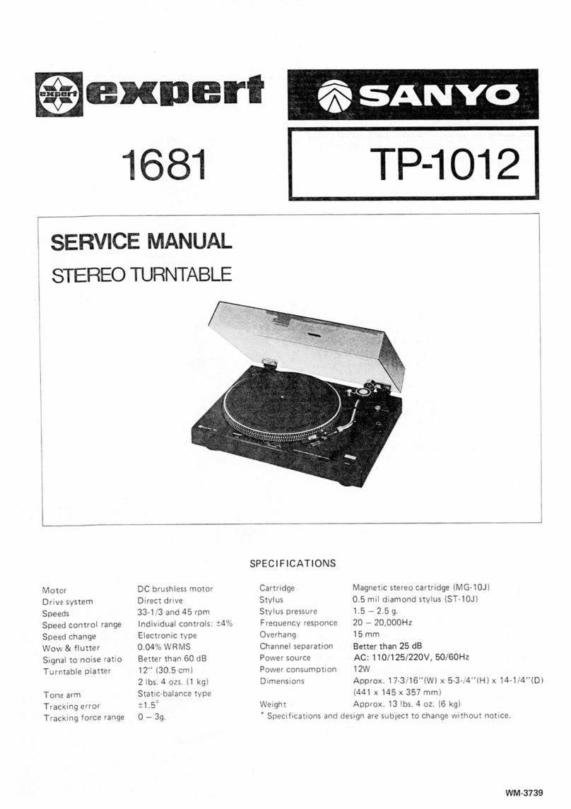
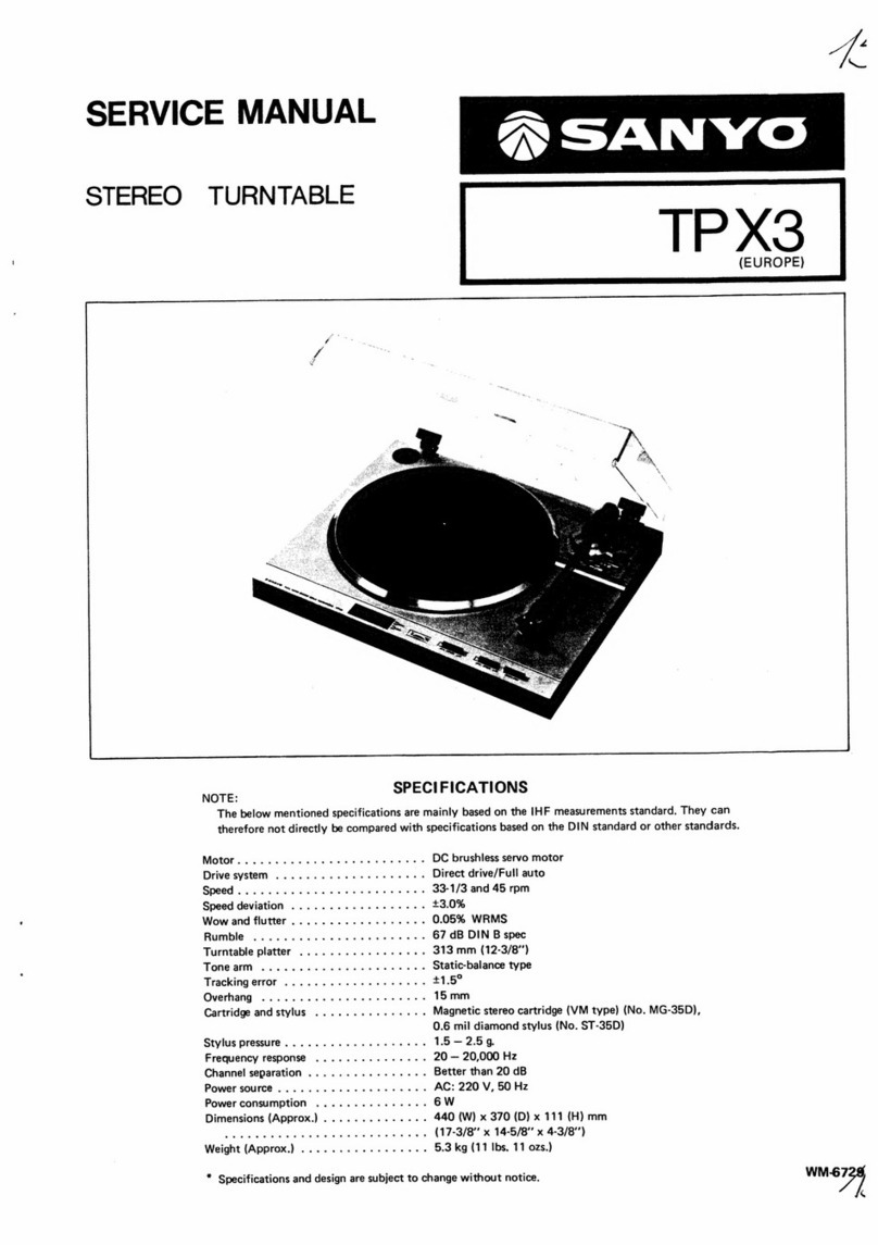
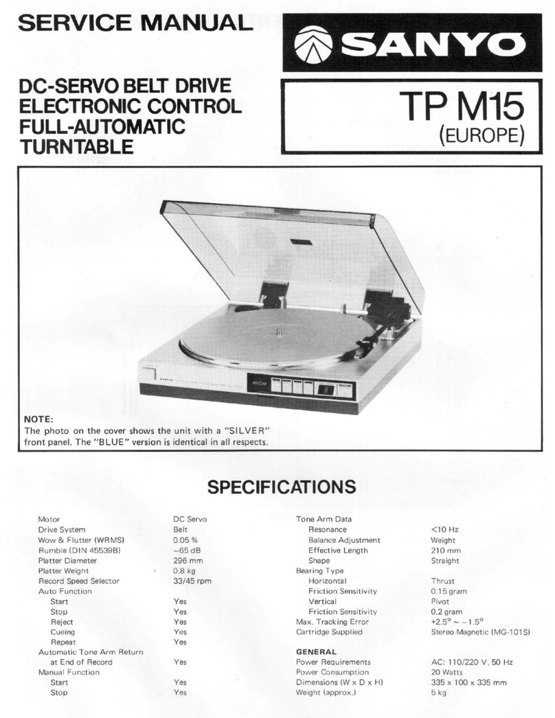
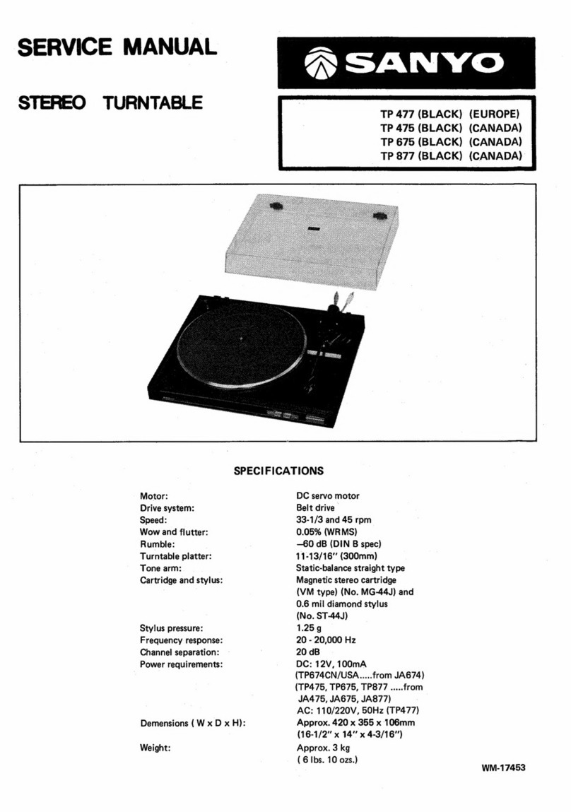
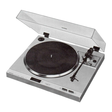
Sanyo TP20 User manual

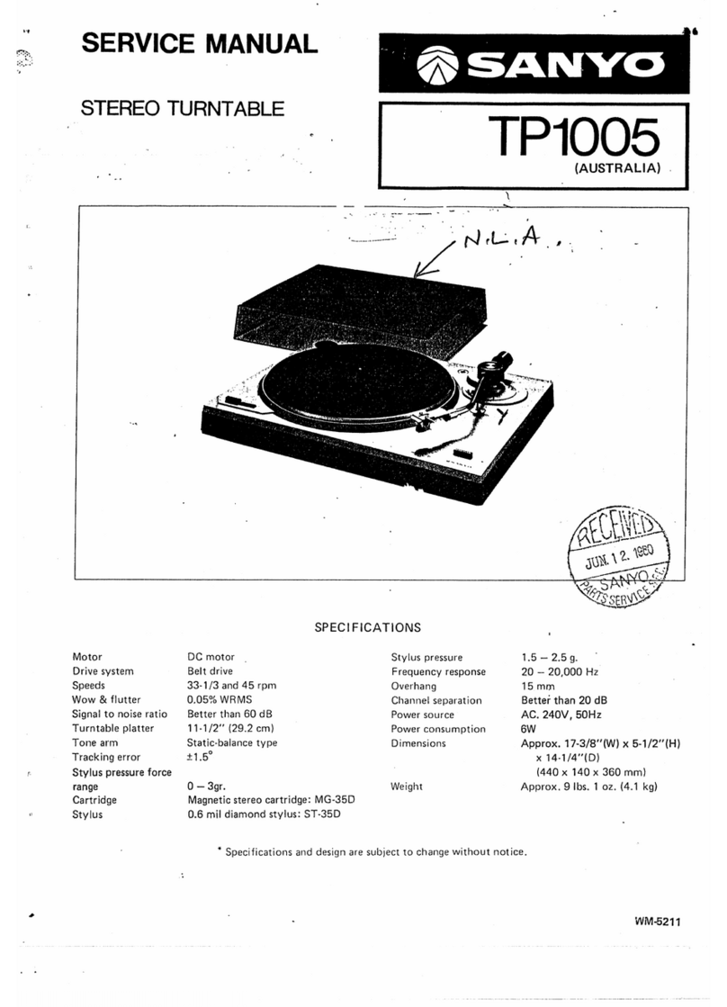
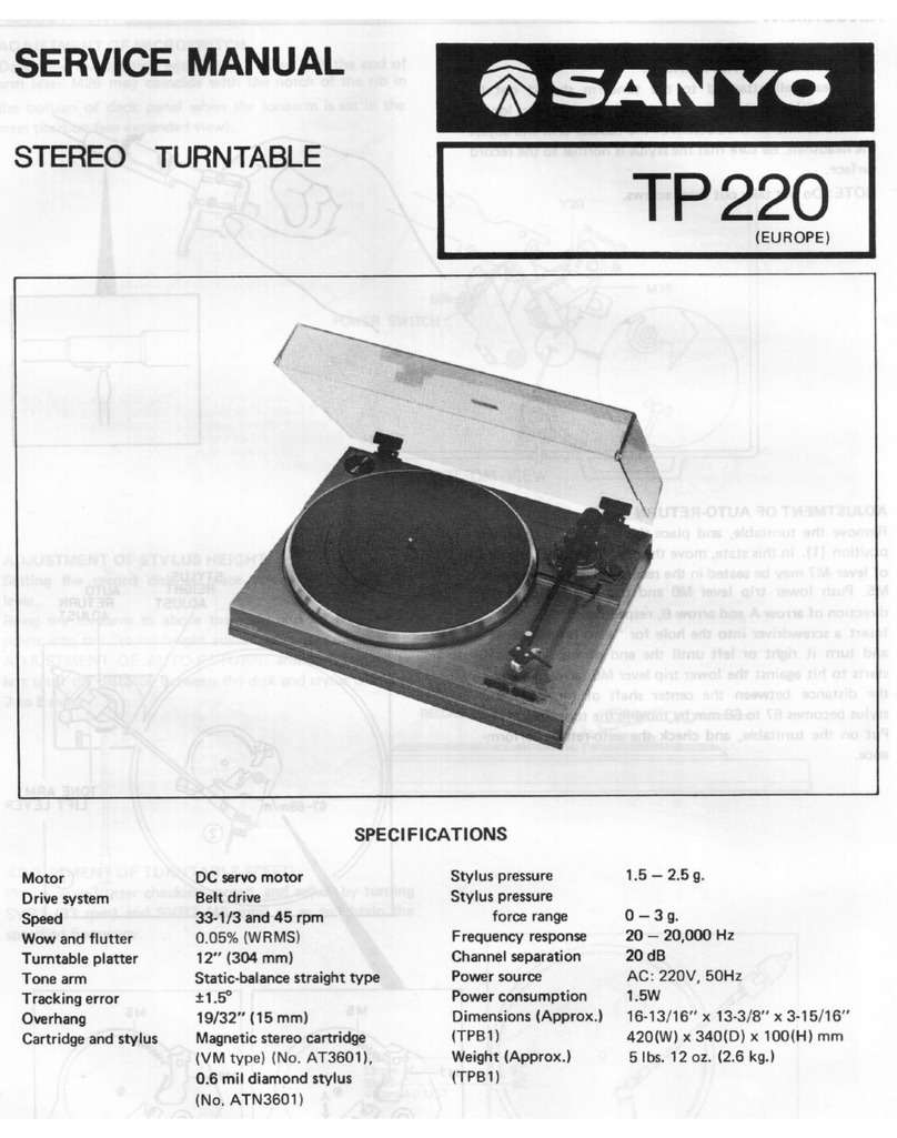
SERVICE
MANUAL
STEREO
TURNTABLE
TP20
(EUROPE)
Motor
Drive
system
Speeds
Wow
&
flutter
Signal
to
noise
ratio
Turntable
platter
Tone
arm
Tracking
error
Cartridge
Stylus
SPECIFICATIONS
DC
motor
Belt
drive
33-1/3
and
45
rpm
0.05%
WRMS
Better
than
60
dB
11-1/2"
(29.2
cm)
Static-balance
type
+1.5°
Magnetic
stereo
cartridge:
(MG-10J)
0.5
mil
diamond
stylus:
(ST-10J)
Stylus
pressure
Frequency
response
Overhang
Channel
separation
Power
source
Power
consumption
Dimensions
Weight
1.5—2.5g.
20
—
20,000
Hz
15
mm
Better
than
25
dB
AC:
220V,
50Hz
6W
Approx.
17-1/2’(W)
x
5-5/8'"(H)
x
14-1/4"'(D)
(440
x
140
x
360
mm)
Approx.
9
Ibs.
1
oz.
(4.1
kg)
*
Specifications
and
design
are
subject
to
change
without
notice.
WM-4316

ADJUSTMENT
ADJUSTMENT
OF
TONEARM
LEVER
Set
the
turntable
unit
upside
down
after
putting
the
tone-
arm
on
the
arm
rest
and
securing
it.
Then,
loosen
the
set
screw
(w/hex
hole)
and
position
the
lever
(M18)
in
such
a
way
that
the
protrusion
of
the
micro-
switch
contacts
the
foremost
end
of
the
lever.
ADJUSTMENT
OF
MICRO-SWITCH
Set
the
turntable
unit
back
in
its
normal
position
(the
turntable
platter
at
the
top).
Loosen
the
round
hend
screw
(Y7)
(see
illustration)
with
a
screwdriver
and
adjust
the
microswitch
position
so
that
the
micro-switch
will
be
turned
on
when
the
tonearm
has
moved
a
little
toward
the
turntable
center.
The
micro-switch
should
be
correctly
positioned
at
a
place
where
it
provides
a
rotational
start
for
the
turntable
when
the
tonearm
head
centers
an
area
35
through
38cm
away
from
the
center.
ADJUSTMENT
OF
AUTO-RETURN
There
is
a
shaft
which
is
accessible
with
an
long
shaft
screwdriver
through
the
hole
below
the
tonearm.
(See
illustration
at
right.)
When
the
stylus
has
reached
a
point
approximately
55mm
from
the
turntable
center
turn
the
shaft
clockwise
or
counter-clockwise
and
select
a
position
where
it
actuates
the
auto-return.
ADJUSTMENT
OF
HEADSHELL
The
headshell
attached
to
the
tonearm
should
not
be
inclined
either
to
the
right
or
to
the
left.
If
necessary,
loosen
the
two
screws
on
the
bottom
of
the
tubular
arm
and
adjust
the
headshell.
Be
sure
that
the
stylus
is
normal
to
the
record
surface.

ADJUSTMENT
ADJUSTMENT
OF
TONEARM
LIFTER
Set
the
cuing
lever
to
UP
and
the
distance
between
the
stylus
and
the
record
to
about
9mm
_
by
adjusting
the
arm
lifter
screw.
ADJUSTMENT
OF
LIFT-UP
LEVER
SPRING
Switch
off
power
when
the
auto-return
has
worked
and
adjust
spring
tension
to
provide
a
clearance
of
11mm
between
the
stylus
and
the
record.
ADJUSTMENT
OF
TURNTABLE
SPEED
Set
the
fine
speed
control
dials
to
their
center
positions
(each
has
three
protrusions,
of
which
only
one
can
be
set
to
the
center).
Make
adjustment
by
inserting
a
screwdriver
into
the
holes.
When
properly
adjusted,
the
zebra
strobo-
scope
marks
on
the
turntable
platter
seem
to
be
stationary
at
the
selected
speed.

CABINET
EXPLODED
VIEW

PARTS
LIST
Ref.
hat
:
Ref.
PACKING
141-6-132T-97210
141-6-144T
-49600
141-6-316T-79800
141-2-337T-10400
141-6-410T-22201
141-6-231T-60700
141-6-231T-35400
141-6-231T-25300
141-6-231T-10200
141-6-231T-10100
141-6-316T-80100
141-6-317T-07500
141-6-317T-06700
141-6-317T-07700
141-6-316T
-88500
123-6-453R-00100
CABINET
141-0-121T-14606
141-0-194T-00700
141
-0-873T-00204
141-0-872T-00201
141
-0-365T
-38402
141-0-365T-42102
141
-0-367T
-30601
141
-0-174T-06600
141-2-251T-06102
141
-2-351T-47500
141
-2-352T-19900
141-2-464T-11800
141
-2-445T-16000
141-2-855T-14200
141-2-683T-32401
141-2-246T
-23000
141
-2-118T-00600
141
-2-126T-27900
141
-2-352T-25300
141-2-135T-48501
141-2-135T-53500
141-2-683T
-33800
23
|
141-2-742T-07300
24
|
141-2-683T-28900
25
|
141-2-851T-73300
26
|
141-2-852T-45600
27
|
141-2-447T-45700
28
|
123-2-472R-00401
29
|
141-2-852T-45700
30
|
141-2-461T-30800
31
|
141-2-472T-06800
32
|
141-2-464T-30000
33
|
141-2-352T-24800
34
|
141-2-322T-48900
35
|
141-2-445T-05000
36
|
141-2-461T-30800
37
|
141-2-853T-63000
2-855T-14700
-2-561T-04200
40
|
141-2-351T-47201
42
|
141-2-472T-01201
14
1-2-340T-00200
141-0-742T-07200
14
1-2-853T-59900
141-2-742T-26300
14
1-2-753T-54900
141-2-241T-21300
-2-852T-52500
Individual
Carton
Styrol
Filler,
Set
Pad,
Top
Ribbon,
Arm
Fixer
Instruction
Manual
Inner
Polyethylene
Bag,
Set
Inner
Polyethylene
Bag,
Sheet
Inner
Polyethylene
Bag,
Inst.
Manual
Inner
Polyethylene
Bag,
Cord
Inner
Polyethylene
Bag,
Accessories
Pad,
Side
Set
Pad,
Turn
Table
Pad,
Sheet
Pad,
Dust
Cover
Pad,
Dust
Cover
Inspection
sheet
Deck
Panel
Assembly
Dust
Cover
Assembly
Rest
Assembly
Lifter
Assembly
Bracket
Switch
Assembly,
Reject
Bracket
Switch
Assembly,
Speed
Bracket
Socket,
Cord
Out
Stand
Assembly
Hinge,
Dust
Cover
Mtg.
Brakcet
Mounting,
Hinge
Mtg.
Spacer,
45
Adaptor
Fixer,
AC
Cord
Rubber
Cushion,
Output
Cord
Mtg.
Coil
Spring,
Lifter
Mtg.
Ring,
Stand
Mtg.
Sheet,
Turn
Table
Turn
Table
Back
Lid
Spacer,
Adjust
height
or
leg
Cover,
PT
Cover,
Motor
Ring,
Turn
Table
Shaft
Lever,
Reject
Ring,
Reject
Coil
Spring,
Reject
Wire
Spring,
Reject
Cushion,
Wire
Spring
(26)
Lug,
Wire
Spring
(26)
Wire
Spring,
Earth
Pipe,
Cushion
Lug,
Arm
Shaft
Mtg.
Fixer,
Outnut
Cord
Spacer,
Micro
Switch
Mtg.
Shield
Plate,
Output
P.C.B
Rubber
Cushion,
Bracket
Switch
Pipe,
Bracket
Switch
Plate
Spring
Coil
Spring,
pull
the
Mechanism
Slide
Flat
Belt,
Turn
Table
Drive
Bracket
Mounting,
Switch
Lug,
Lead
Retainer
Rope
0.5¢
x
50mm
Lever
Assembly,
Lift
up
lever
Plate
Spring
Lever
Shaft
Veil
Spring
Wire
ak
ek
ek
es
fL.)
N
Pm
ePrRrNNND
BNUNN
=
|
Bea
W&
2a
a
Bs
BB
BB
BB
BH
BB
HHH
KHNN|
—
2
a
—
eo
eS
PMP
mmr
Lo
ELECTRICAL
PARTS
&
ARM
(JPU1005UM)
141-4-230T-84800
141-2-464T-08700
4-237T-00100
4-222T-39577
4-222T-39576
141-0-230T-44200
4-230T-19400
4-251T-92000
4-243T-77172
4-243T-15171
4-231T-61900
141-2-464T
-08700
123-2-472R-00600
123-2-472R
-00400
141-0-743T-05906
141-2-853T-53901
141-0-687T-01400
141-0-286T-01000
141-2-445T-20300
4-243T-15800
4-243T-15871
4-243T-15872
4-243T-15873
141-2-421T-23700
141-2-417T-18100
141-2-453T-32200
4-157T-00801
4-156T
-00500
141-2-742T-13100
141-2-687T-01600
Description
Printed
Circuit
Board
Assembly,
POWER
Fixer
Terminal,
Wrapper
Pin
Semi
Fixed
Resistor
50kB
Semi
Fixed
Resistor
20kB
Diode
DS18
Diode
DS17
Electrolytic
1000uF
+100
—10%
16WV
Printed
Circuit
Board
Assembly,
AC
Relay
Printed
Circuit
Board,
Output
Relay
Power
Transformer,
110/220V
50Hz
Power
Supply
Cord
Lead
Cord,
Output
Cord
DIN
type
Switch,
Micro
Fixer,
Mylar
(61)
Mtg.
Lug,
Earth
Mylar
Capacitor
0.047uF
+20%
50WV
Lug,
Earth
Arm
Assembly
Plate
Spring
Weight
Assenbly
Tapping
Screw
2
x
4mm,
Plate
Spring
Mtg.
Head
Shell
Assembly
Rubber
Cushion
Lead
Cord,
LH
Lead
Cord,
LE
Lead
Cord,
RH
Lead
Cord,
RE
Special
Screw
Stud
Nut
Washer,
Nyton
Cartridge
Assembly
Stylus
Lever,
Head
Shell
Fingure
Weight,
Sub
Weight
AGREE
Maiev
isc
te:
ln

MECHANISM
EXPLODED
VIEW
M19
yw
M21
5—M18
:
ama
Lee
—M20
v4
v18—s
=
Vi8
wis
a
31
v9
>
M144
ER
a
cae
.
X33
aan
.
|
ym
25
os)
M25
il
s
Y21-@
AINS
fe
Y21
Le

PARTS
LIST
Ref.
Axe
:
ee
ee
MECHANISM
(PM1005UM
Ref.
ae
y
M1
141-0-581T-08900
|
Gear
Assembly,
Main
Gear
1
Screw,
Pan
Head
3
x
6mm
2
M2
141-0-731T-65100
|
Slide
Assembly,
Main
Slide
1
Screw,
Pan
Head
3
x
8mm
1
M3
141-2-453T-30701
|
Washer,
GNW5.2
x
8
x
0.25mm
1
Screw,
Pan
Head
3
x
10mm
2
M4
|
141-2-457T-23200
|
Special
Washer,
‘’E’’
Ring
4mm
2
Screw,
Pan
Head
3
x
14mm
2
M5
141-0-747T-17500
|
Bracket
Lever
Assembly,
Life
Up
1
Screw,
Flat
Head
3
x
10mm
1
Lever
Mtg.
Screw,
Binding
Head
4
x
12mm
4
M6
141-0-741T-20700
|
Lever
Assembly,
Lift
Up
Lever
1
Screw,
Tapping
2.6
x
6mm
1
M7
141-2-853T-51100
|
Plate
Spring,
Lift
Up
1
Screw,
Tapping
3
x
12mm
1
M8
141-2-457T-23100
|
Special
Washer,
‘’E’’
Ring
3mm
1
Screw,
Tapping
3
x
4mm
1
M9
141-2-472T-01001
|
Lug,
Earth
1
Screw,
Tapping
3
x
6mm
2
M10
|
123-2-472R-00600
|
Lug,
Earth
1
Screw,
Tapping
3
x
8mm
16
M11
141-0-351T-47100
|
Bracket
Mounting
Assembly
1
Nut,
Hexagon
2.6mm
1
M12
|
141-0-751T-02800
|
Shaft
Assembly,
Turn
Table
1
Nut,
Hexagon
3mm
7
M13
141-2-742T-06700
|
Lever,
Trip
1
Washer,
Spring
2.6mm
1
M14
141-2-742T-22300
|
Lever,
Switch
Operation
1
Screw,
Headless
3
x
4mm
1
M15
|
141-2-457T-23000
|
Special
Washer,
Lever
(M14)
Mtg.
1
Screw,
Headless
4
x
4mm
2
“E"™
Ring
2mm
Screw,
Headless
with
Hexagon
2
M16
4-527T-10800
|
DC
Motor
1
Hole
3
x
4mm
M17
141-2-661T-71800
|
Pulley,
Motor
Mtg.
1
Screw,
Tapping
with
Washer
M18
|
141-0-742T-25400
|
Léver
Assembly,
Arm
Lever
1
3
x
8mm
M19
141-2-753T-52600
|
Shaft,
AUTO
RETURN
ADJUST
1
Screw,
Tapping
with
Washer
M20
|
141-2-457T-23101
|
Special
Washer,
Shaft
(M19)
Mtg.
1
3
x
10mm
M21
141-2-851T-73500
|
Coil
Spring,
Arm
Lever
Restore
1
Screw,
Tapping
with
Washer
M22
141-0-577T-06100
|
Bracket
Bearing
Assembly,
Lift
Up
1
3
x
12mm
M23
|
141-0-573T-09601
|
Bearing
Assembly,
Arm
Stand
1
Washer,
3
x
10
x
0.5mm
M24
|
141-2-378T-09000
|
Bracket,
Motor
Mtg.
1
Washer,
3
x
8x
0.5mm
M25
|
141-2-447T-38600
|
Cushion,
Motor
Mtg.
6
Hexagon
Nut,
12
x
0.75mm
M26
|
141-2-421T-27300
|
Special
Screw,
Motor
Mtg.
3
or
(141-2-462T-30800
Pipe
3
141-2-453T-01700°)
Washer,
GNW
3
x
10
x
1mm
3
Pan
Head
Screw
2.6
x
8mm
3
M27
123-2-472R-00401
Lug,
Earth
1
ARM
EXPLODED
VIEW
102
SCREW
MOUTING
_
104~107

PARTS
LIST
M27
ARM
Ref.
Part
No.
MECHANISM
(PM1005UM)
141-0-581T-08900
141-0-731T-65100
141-2-453T-30701
141-2-457T-23200
141-0-747T-17500
141-0-741T-20700
141-2-853T-51100
141-2-457T-23100
141-2-472T-01001
123-2-472R-00600
141-0-351T-47100
141-0-751T-02800
141-2-742T-06700
141-2-742T-22300
141-2-457T-23000
4-527T-10800
141-2-661T-71800
141-0-742T-25400
141-2-753T-52600
141-2-457T-23101
141-2-851T-73500
141-0-577T-06100
141-0-573T-09601
141-2-378T-09000
141-2-447T
-38600
141-2-421T-27300
or
(141-2-462T
30800
141-2-453T-01700
123-2-472R-00401
EXPLODED
VIEW
102
)
le:
Gear
Assembly,
Main
Gear
Slide
Assembly,
Main
Slide
Washer,
GNW5S.2
x
8
x
0.25mm
Special
Washer,
‘‘E’’
Ring
4mm
Bracket
Lever
Assembly,
Life
Up
Lever
Mtg.
Lever
Assembly,
Lift
Up
Lever
Plate
Spring,
Lift
Up
Special
Washer,
‘‘E’’
Ring
3mm
Lug,
Earth
Lug,
Earth
Bracket
Mounting
Assembly
Shaft
Assembly,
Turn
Table
Lever,
Trip
Lever,
Switch
Operation
Special
Washer,
Lever
(M14)
Mtg.
“E"
Ring
2mm
DC
Motor
Pulley,
Motor
Mtg.
Léver
Assembly,
Arm
Lever
Shaft,
AUTO
RETURN
ADJUST
Special
Washer,
Shaft
(M19)
Mtg.
Coil
Spring,
Arm
Lever
Restore
Bracket
Bearing
Assembly,
Lift
Up
Bearing
Assembly,
Arm
Stand
Bracket,
Motor
Mtg.
Cushion,
Motor
Mtg.
Special
Screw,
Motor
Mtg.
Pipe
Washer,
GNW
3
x
10
x
1mm
Pan
Head
Screw
2.6
x
8mm
Lug,
Earth
—_
104~107
—
A).
—
2
ot
3
oat
od ot
—
=
—
=
WW
W
WOO
-
-
aS
MP
SB
eae
ee
Ref.
No.
SCREW
MOUTING
Screw,
Pan
Head
3
x
6mm
Screw,
Pan
Head
3
x
8mm
Screw,
Pan
Head
3
x
10mm
Screw,
Pan
Head
3
x
14mm
Screw,
Flat
Head
3
x
10mm
Screw,
Tapping
2.6
x
6mm
Screw,
Tapping
3
x
12mm
Screw,
Tapping
3
x
4mm
Screw,
Tapping
3
x
6mm
Screw,
Tapping
3
x
8mm
Nut,
Hexagon
2.6mm
Nut,
Hexagon
3mm
Washer,
Spring
2.6mm
Screw,
Headless
3
x
4mm
Screw,
Headless
4
x
4mm
Screw,
Headless
with
Hexagon
Hole
3
x
4mm
Screw,
Tapping
with
Washer
3
x
8mm
Screw,
Tapping
with
Washer
3
x
10mm
Screw,
Tapping
with
Washer
3
x
12mm
Washer,
3
x
10
x
0.5mm
Washer,
3
x
8
x
0.5mm
Hexagon
Nut,
12¢
x
0.75mm
Screw,
Binding
Head
4
x
12mm
Q'ty
NN
AAP
yA
ON
HRP
RPRANN-H
ND

SCHEMATIC
DIAGRAM
P.T
33rpm
nov}
atte
a
@
|
45rpm
faa
|
=
=
oO
wh
:
D1
D2
N
/
a
AC
DS-18
|
DS-17
>
=
INPUT
|
CW
Na
=
=
|
|
|
|
i
|
©
-+
50
HZ
|
=~
i
|
ry
|
o)
|
a
d
|
Sf
Z|
>
a
|
YELLOW
MOTOR
R
e
OC)
t @
a
ne
Oe
S]
THERMAL
FUSE
C1
0,047
S1
MOTOR
SWITCH
S2
SPEED
CHANGE
SWITCH
WIRING
DIAGRAM
YELLOW
pe
od
a
Noe
oe
P.T
BLUE
O
AC
INPUT
50
Hz
YELLOW
Lzes
(aa
ame
ae
ee
ee
ee
ee
RED
|
THERMAL
:
Leleetatoyels
ea
I
ect
S1-----—-MOTOR
SWITCH
Cy
ee
SPEED
CHANGE
SWITCH
§3------
VOLTAGE
SELECT
SWITCH
SANYO
ELECTRIC
TRADING
CO.,
LTD.
33,
Hiyoshi-cho
2-chome,
Moriguchi-shi,
Osaka-fu,
570
Japan
Aug./'79/1300
Printed
in
Japan
Table of contents
Other Sanyo Turntable manuals