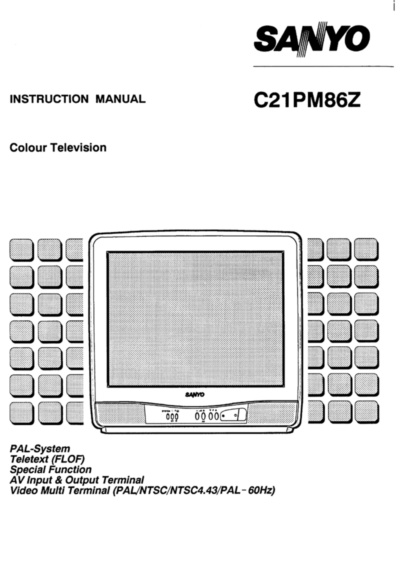
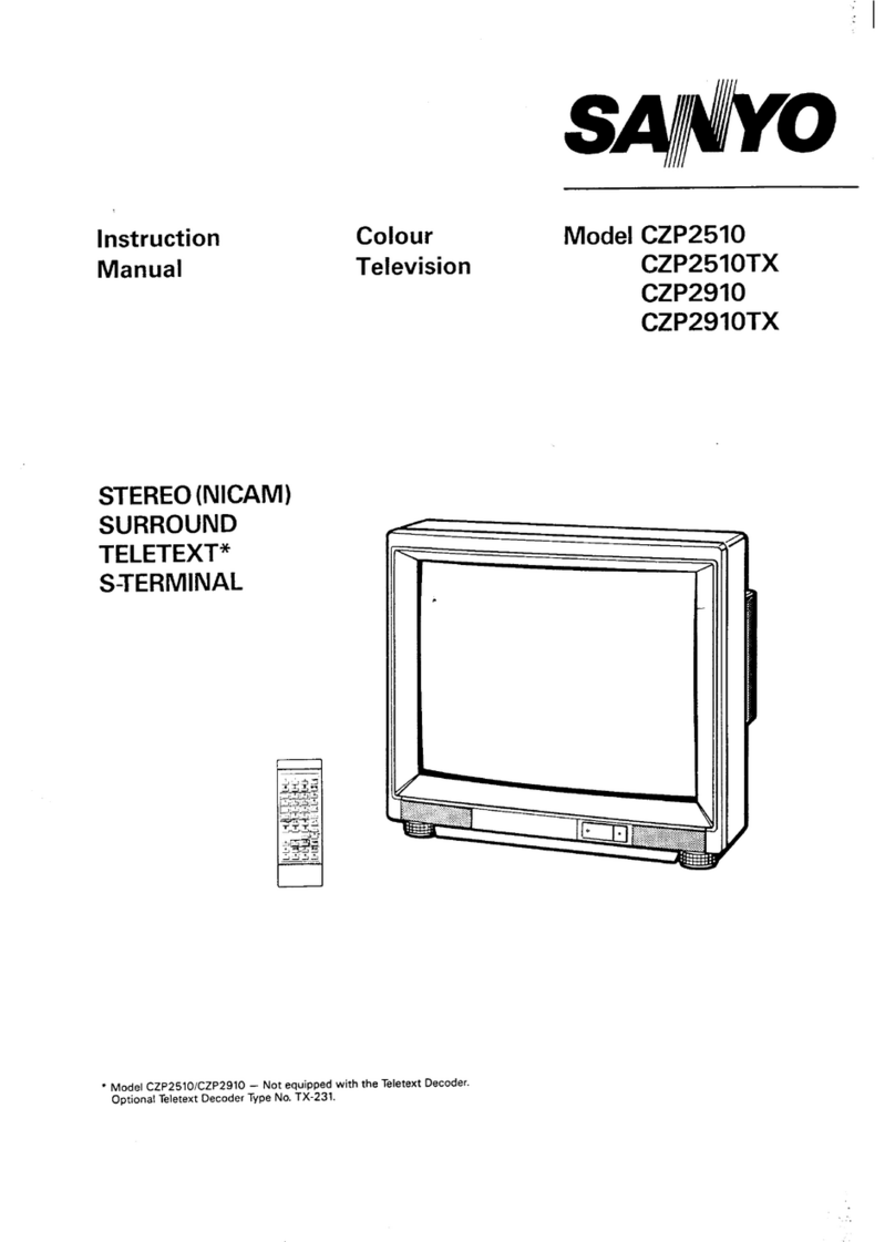
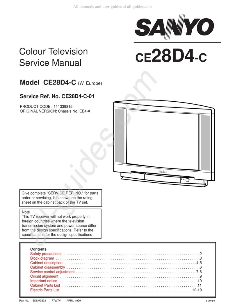
Sanyo C14EA80D User manual

Service
Manual
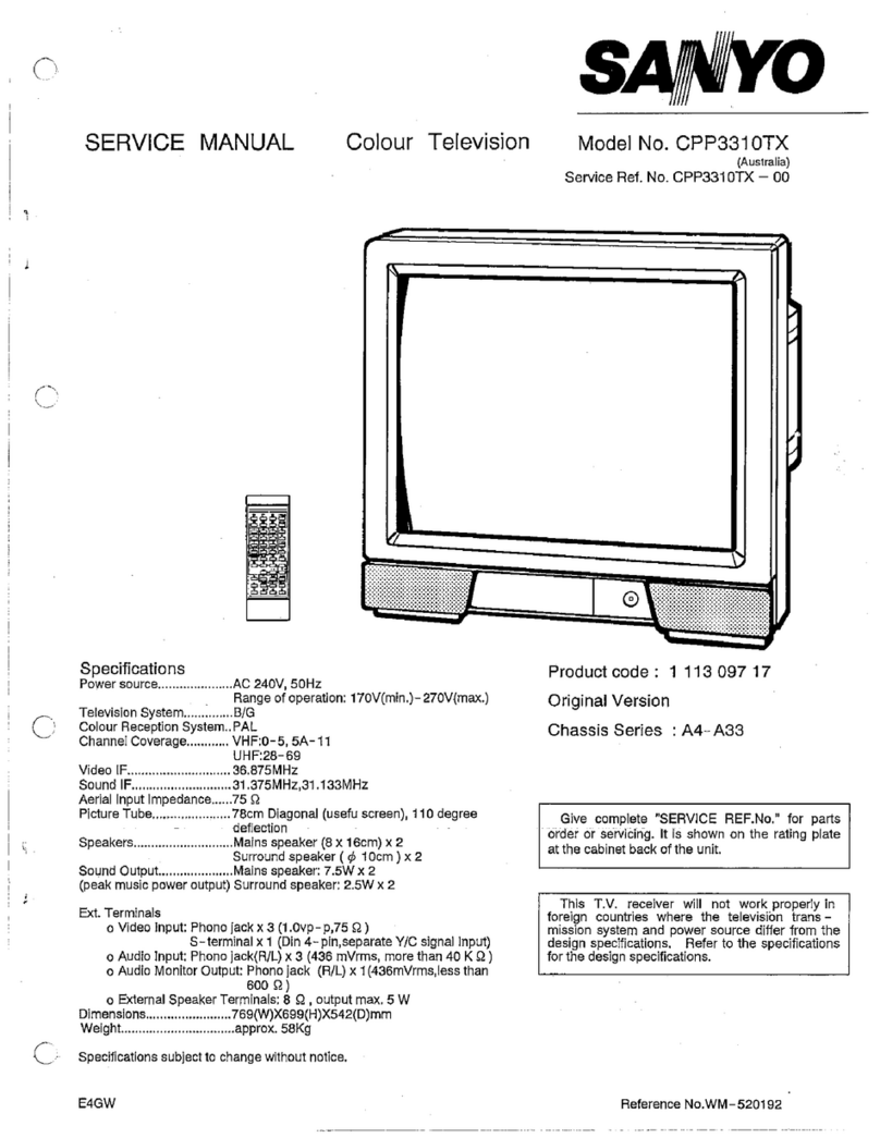
Specification
Power
source
Television
system
Colour
system
Receiving
channel
Aerial
input
impedance
AV
terminal
21
Pin
socket
Sound
output
Picture
tube
(Visible
picture
diagonal)
Dimensions
Weight
SKSMO0055
Colour
Television
S
O
Model
No.
Ci4EA80D
(GERMANY
ITALY)
Service
Ref.
No.
C14EA80D-00
C14EA80D-01
AC
220~240V
50Hz
System
B/G
PAL
VHF
E2~E12,
A-H,
H1, H2,
UHF
21~69
CATV
S1~S20,
X, Y,
Z
750hm
CENELEC
standard
2
watts
37cm
diagonal,
90
degree
34cm
370(W)
X
331(H)
X
381.5(D)mm
9.0
Kg
PRODUCT
CODE
1113
183
03(C14EA80D)
ORIGINAL
VERSION
Chassis
No.
EC2-A
14
Give
complete
"SERVICE
REF.
NO."
for
parts
order
or
servicing
,
it
is
shown
on
the
rating
sheet
on
the
cabinet
back
of
the
TV
set.
Note:
This
TV
receiver
will
not
work
properly
in
foreign
countries
where
the
television
transmission
system
and
power
source
differ
from
the
design
specifications.
Refer
to
the
specifications
for
the
design
specifications.

SAFETY
PRECAUTION
1:
An
isolation
transformer
should
be
connected
in
the
3:
When
replacing
a
chassis
in
the
cabinet,
always
cv.
power
line
between
the
receiver
and
the
AC
line
when
certain
that
all
the
protective
devices
are
installed
a
service
is
performed
on
the
primary
of
the
converter
properly,
such
as,
control
knobs,
adjustment
covers
transformer
of
the
set.
or
shields,
barriers,
isolation
resistor-capacitor
2:
Comply
with
all
caution
and
safety-related
notes
networks
etc.
provided
on
the
cabinet
back,
inside
the
cabinet,
on
the
chassis
or
the
picture
tube.
Before
returning
any
television
to
the
customer,
the
service
technician
must
be
sure
that
it
is
completely
safe
to
operate
without
danger
of
electrical
shock.
X-RADIATION
PRECAUTION
The
primary
source
of
X-RADIATION
in
the
television
receiver
is
the
picture
tube.
The
picture
tube
is
specially
constructed
to
limit
X-RADIATION
emissions.
For
continued
X-RADIATION
protection,
the
replacement
tube
must
be
the
same
type
as
the
original
including
suffix
letter.
Excessive
high
voltage
may
produce
potentially
hazardous
X-RADIATION.
To
avoid
such
hazards,
the
high
voltage
must
be
maintained
within
specified
limit.
Refer
to
this
service
manual,
high
voltage
adjustment
for
specific
high
voltage
limit.
If
high
voltage
exceeds
specified
limits,
take
.'
necessary
corrective
action.
Carefully
follow
the
instructions
for
+B1
volt
power
supply
adjustment,
and
high
voltag
adjustment
to
maintain
the
high
voltage
within
the
specified
limits.
PRODUCT
SAFETY
NOTICE
Product
safety
should
be
considered
when
a
component
replacement
is
made
in
any
area
of
a
receiver.
Components
indicated
by
mark/\in
the
parts
list
and
the
schematic
diagram
designate
|
components
in
which
safety
can
be
of
special
significance.
It
is
particularly
recommended
that
only
parts
designated
on
the
parts
list
in
this
manual
be
used
for
component
replacement
designated
by
mark
/\.
No
deviations
from
resistance
wattage
or
voltage
ratings
may
be
made
|
for
replacement
items
designated
by
mark
A\.

BLOCK
DIAGRAM
Note:
This
is
a
general
diagram
for
all
models
and
therefore
differs
slightly
from
the
actual
block
diagram.
a
ieee
“Ody
'
|
Th
JexvadS
uooaeq
a
LSeOl
‘dV
olpny
(p9ZSNv)
LZLOI
‘dW
‘HOA
(zeszv1)
LSvol
8
6
{AS}
{A8:Za'
\
AV14q
Hk
NOILO31435q¢
(L99pvdl)
/HNO1OO/Al
0LZOl
(L9E8VaL)
LOLOI
(M07
UBW)ASL
SE
CUOA)Ave:bE
(opny)ASt:2
H
URW
)ADES
Id
WNDdIO
1aMOg
‘SNVULI...
YALYSANO9
LLeL
re
>
.
S
vos
AS‘68.
7
Acl:9d
BIOs
:
AYOWSWN
06291
MS
GNV
(OL6ZV1)
OLZOl

CIRCUIT
DESCRIPTION
1.POWER
SUPPLY
The
power
supply
circuit
of
the
EC2-A
chassis
is
composed
of
a
rectifier
smoothing
circuit,
an
oscillation
circuit,
a
control
circuit
and
an
output
rectifier
circuit.
The
AC
input
voltage
is
full-wave
rectified
by
the
rectifier
smoothing
circuit,
and
an
unstable
DC
voltage
is
generated
at
both
terminals
of
the
smoothing
capacitor
C307.
This
voltage
is
input
to
the
oscillation
circuit.
The
oscillation
circuit
is
provided
with
a
blocking
oscillator
circuit
that
switches
the
switching
transistor
Q313
ON
and
OFF,
and
an
oscillation
frequency
and
a
duty
square
wave
pulse
are
generated
in
the
input
windings
according
to
operation
of
the
control
circuit.
A
square-wave
pulse
whose
size
is
dependent
on
the
turn
ratio
of
the
input
and
output
windings
is
obtained
in
the
output
winding.
This
is
rectified
in
the
output
rectifier
circuit,
and
the
desired
DC
voltage
is
obtained.
2.IF
&
DEFLECTION
(TDA8361)
The
IF
output
signal
from
the
tuner
passes
through
the
SAW
filter,
and
it
is
input
to
pin45
and
pin46
of
1C101.
The
signal
input
to
the
IC
passes
through
the
IF
amplifier,
video
detection
and
video
amplifier
circuits
and
is
output
from
pin7
as
a
composite
video
signal.
And
after
this
signal
is
converted
to
impedance
at
Q122,
supplies
to
the
video
and
chroma
amplifier
stages.
The
output
signal
from
pin7
passes
through
the
6.0MH2z(I)/5.5MHz(B/G)
trap
circuit
of
X151,
and
it
is
input
to
pin5
of
1C101.
The
signal
input
to
the
IC
passes
through
the
SIF
amplifier,
FM
detector,
external
audio
switch
and
audio
output
circuit,
and
it
is
then
output
from
pin50
as
audio
drive
signal.
The
sync.-separation
circuit
separates
the
video
signals
applied
to
pint3
or
pin15
to
vertical-
and
horizontal-sync.
signals
respectively.
The
horizontal
oscillator
requires
no
external
components
and
is
fully
integrated.
The
oscillator
is
always
running
when
the
Start-pin36
is
supplied
with
8V.
Horizontal
drive
signal
is
output
from
pin37.
VR401
is
for
adjustment
of
the
horizontal
centering.
The
separated
vertical-sync.
signal
from
sync.
separation
circuit
passes
through
the
vertical-
separation
circuit,
and
applied
to
trigger
divider
circuit.
The
horizontal
oscillation
pulse
and
input
vertical
sync.
pulse
are
monitored
by
the
trigger
divider
circuit,
and
Switching
50Hz
and
60Hz
system,
the
vertical
amplitude
automatically
adjusted
for
50Hz
and
60Hz.
The
output
signal
from
the
trigger
divider
is
triggered
vertical
oscillation
circuit
consisting
of
C401,
R402
and
pin42,
and
vertical
drive
pulse
is
output
from
pin43.
VR431
is
for
changing
the
amount
of
AC
feedback
applied
to
pin41
and
for
adjustment
of
the
vertical
amplitude.
3.VIDEO
CHROMA
&
R.G.B.
(TDA8361)
The
composite
video
signal
output
from
the
pin7
of
IC101
passes
through
Q122/Q124,
and
it
is
supplied
to
pini3.
The
external
video
signal
output
from
SCART
is
supplied
to
piniS.
The
video
signal
input
to
pin13
or
pints
is
separated
to
luminance
(Y)
signal
and
chroma
signal
in
1C101.
These
pins
are
used
in
common
with
H/V-sync.
separation
input.
The
peaking
of
Y
signal
is
adjusted
by
DC
voltage
of
pini4.
(“SHARPNESS”
control)
The
chroma
signal
is
divided
into
R-Y and B-Y
chroma
signals,
demodulated
in
1C101,
and
output
from
pin30
(R-Y)
and
pin31
(B-Y).
These
chroma
signals
pass
through
the
1H
delay
line
circuit
(IC270),
and
they
are
input
to
pin29
(R-Y)
and
pin28
(B-Y).
These
R-Y/B-Y
signals
pass
through
RGB
matrix
circuit
and
RGB
selector
circuit
of
1C101.
The
internal
RGB
signals
are
generated
in
RGB
matrix
circuit
and
the
RGB
selector,
consisting
linear
amplifiers,
clamps
and
selects
either
the
internal
RGB
signals
or
the
external
OSD
signal
from
pin23(G).
In
this
stage,
the
OSD
signal
which
is
switched
by
blanking
signal
from
pin21
is
superimposed
into
internal
RGB
signals.The
colour
gain
is
controlled
by
DC
voltage
of
pin26.
(“COLOUR?”
control)
The
contrast
control
voltage
present
at
pin25,
and
the
brightness
control
voltage
present
at
pint7
controls
DC
level
of
RGB
signals.
The
RGB
signals
are
finally
buffered
before
being
available
at
the
RGB
output
pins
[pin20
(R),
pini9
(G),
pin18
(R)].
4.AUDIO
OUTPUT(AN5265)
The
audio
signal
output
from
pin50
of
IC101
is
input
to
pin2
of
1C171
and
passes
through
the
pre-amplifier
circuit
and
drive
circuit,
after
which
it
is
input
to
the
audio
amplifier.
The
audio
amplifier
is
an
SEPP
(single-ended,
push-pull)
OTL
type
and
output
to
pin8
to
directly
drive
the
speaker.
5.VERTICAL
OUTPUT
(LA7832)
An
IC
(LA7832)
is
used
for
the
vertical
output
circuit
in
this
chassis.
The
vertical
drive
pulse
from
pin43
of
10101
is
input
to
pin4
of
1C451.
This
pulse
drives
1C451,
and
vertical
scanning
is
performed.
In
the
first
half
of
scanning
a
deflecting
current
is
output
from
pin2
and
passes
through
the
following
path:
Vcec(B4)
—~
D451
—
pin3
>
pin2
—
DY
~
C461
—
VR431/R459.
An
electric
charge
is
then
stored
in
C461.
In
the
last
half
of
scanning
the
current
path
is
C461
—
DY
—
pin2
—
pint
~
VR431/R459
—
C461.
In
this
way,
an
amplifying
sawtooth
waveform
current
flows
directly
to
DY
to
perform
electron
beam
defection.
Next,
in
the
first
half
of
the
banking
period
the
vertical
drive
pulse
suddenly
becomes
OFF,
and
in
order
to
reduce
the
current
flowing
to
DY,
the
current
path
becomes
as
follows
by
the
inductance
of
DY:
DY
—
pin2
—
pint
—
VR431/R459
—
C461
—
DY.
Also,
when
the
charge
of
DY
has
dissipated,
the
current
path
becomes
Vcc24V
—
pin6
—
pin7
—
C452
-+
pin3
>
pin2-
DY
—
C461
—
VR431/R459,
and
when
the
prescribed
current
value
is
reached,
the
vertical
drive
pulse
becomes
ON.
This
completes
one
cycle.
6.HORIZONTAL
OUTPUT
A
horizontal
oscillation
signal
is
output
from
pin37
of
1C101
and
switches
the
drive
transistor
Q431.
This
switching
signal
is
current
amplified
by
the
drive
transformer
T431
and
drives
the
output
transistor
Q432.
When
Q432
becomes
ON,
an
amplifying
current
flows
directly
to
DY
through
C441/442
-
DY
—
0432
—
GND,
-4-
ar

and
defection
is
performed
in
the
last
half
of
the
scanning
period.
Next,
when
Q432
becomes
OFF,
the
charge
that
had
been
stored
in
DY
up
to
that
point
releases
a
resonance
current
to
the
resonant
capacitors
C435,
C444
and
C445
and
charges
them.The
current
stored
in
C435,
C444
and
C445
is
then
flowed
back
to
DY,
and
an
opposite
charge
is
then
stored
in
DY.
This
opposite
charge
then
switches
the
dumper
diode
in
Q432
ON,
the
resonance
state
is
completed,
and
an
amplifying
current
is
then
flowed
again
directly
to
DY
through
the
dumper
diode.
By
this
means,
deflection
in
the
first
half
of
the
scanning
period
is
performed,
and
when
Q432
becomes
ON
at
the
end
of
the
first
half
of
the
scanning
period,
deflection
during
the
last
half
is
begun,
thus
completing
one
cycle.
7.CPU
Pin
description
Pint:
H-sync.
input
(Horizontal
pulse
for
OSD)
Pin2:
\V-sync.
input
(Vertical
pulse
for
OSD)
Pin3:
Volume
contro!
output
(6-bit
DAC)
Pin4:
Colour
control
output
(6-bit
DAC)
Pin5:
Brightness
control
output
(6-bit
DAC)
Pin6:
Contrast
control
output
(6-bit
DAC)
Pin7/8:
Not
used
(GND)
Pin9:
TV/AV
output
(L:AV
mode)
Pinti0:
AFT
ON/OFF
output
(L:AFT
ON)
Pini1:
Not
used
(GND)
Pini2:
l2C
bus
SCL
(Serial
clock
for
memory)
Pin13:
12C
bus
SDA
(Serial
date
for
memory)
Pin14:
Tuning
voltage
output
Pini5:
Ident
signal
input
(L:No
signal)
Pin16:
R/C
signal
input
Pini7/18:
Band
select
option
input
Pini9:
Not
used
(Open)
Pin20:
SCART
auto
switch
input
(L:VCR
Play)
Pin21/22:
Band
selector
output
Pin23:
Supply
Ground
Pin24:
Oscillator
input
for
CPU
Pin25:
Oscillator
output
for
CPU
Pin26:
Supply
Ground
Pin27:
Power
supply(+5V)
Pin28:
Oscillator
output
for
OSD
Pin29:
Oscillator
input
for
OSD
Pin30:
Reset
input
Pin31:
Protect
signal
input
(L:Power
circuit
defects)
Pin32:
Sync.
ID
signal
input
Pin33:
AFT
signal
input
Pin34:
Keyboard
scan
2
Pin35:
Keyboard
scan
1
Pin36~45:
Not
used
(GND)
Pin46:
Not
used
Pin47:
Mute
output
in
no
picture(FTZ
mute)
Pin48:
Power
ON/OFF
output
(H:ON)
Pin49:
Blanking
output
for
OSD
Pin50:
Not
used
(Open)
Pin51:
Green
output
for
OSD
Pin52:
Not
used
(Open)

INSTALLATION
AND
SERVICE
ADJUSTMENT
:
TU-AFT
ADJ.
MAIN
BOARD
Bi
POWER
ADJUSTMENT
S
a
a
—
=|
=
{Osos
T
[
TT
J
“TJ
[_fswros
swro2{
[|
jsw7ot
S|
22
|
PE
swe
gwros
swios
Q708
A
<|
ea
w
=:
/|
008
2
a
Leal
oreo
CPU
5
SB
ge
1C701
fe)
o
1C790
0851
ass3
a
-
O17
cc
Memory
ass2
ey
Lava
TRF
10351
1382
$1220
fs}
3
[SERVICE
Sw
5
“pei
=
ee
3
By
12
Reg.
8V
Reg.
as
:
2
a
a
Q836
Ja,
™
N
5
1
erss2
H
Bei
me
@
Teer
[C451
a
i
1C104
ge
oe
=
a?
gud
TP-F
IF/Detiection/Colour
}
:
a
i
i
TP-E2
©
me
:
a
VR120
:
-
das
1H
Delay)
:
3/2]
Dace
i
ae
3
T431
@
size
:
veo:
|?)
.gyor
Ce
i
=
;
aes
(C270
H-CENTER
owe
ai
a
H-drive
Sa
j
a
:
2
be
5
ccenneeseaceaevenescet
ms
n
SE
fF
icetenntttanmnncetcnnnnenntenantcnannnnsnnented
og
K801
é
Kesq
Sé
SCART
=m
bil
TP-H
TP-G
|
|
FOCUS
ADJ.
H-WIDTH
CONFIRM
|v-SIZEADJ.
|
H-CENTER
ADJ.
TU-AGC
ADJ.
GRAY
SCALE
AND
TRACKING
ADu.
B-DRIVE
R-DRIVE
B-BIAS
G-BIAS
R-BIAS
CRT
BOARD
<<
<x
7
<<
7
SV
pei
a
pe]
a
a
a
c~)
X)
=
i)
np
we
Q601
Q621
Q611
Q640
o
ew
@
aaa
K6P
-6-

SERVICE
CONTROL
ADJUSTMENT
B1
POWER
SUPPLY
ADJUSTMENT
1.
Set
VR351
to
be
mechanical
center
before
pressing
the
main
switch.
2.
Tune
the
receiver
to
PAL
circular
pattern.
3.
Set
brightness
and
contrast
controls
to
normal.
4,
Connect
digital
V-meter
to
R351.
5.
By
using
VR351,
adjust
voltage
to
130
=
O5V.
TU-AFT
ADJUSTMENT
1.
Tune
the
receiver
to
the
clearest
station.
2.
By
using
L230,
adjust
AFT
to
obtain
the
best
picture.
AGC
ADJUSTMENT
NOTE:
Do
not
attempt
this
adjustment
with
weak
signal.
+.
Tune
the
receiver
to
the
clearest
station.
2.
Set
AGC
VA(VR120)
in
direction
which
causes
snow
noise
to
appear,
then
in
the
opposite
direction
until
snow
noise
just
disappears.
GREY
SCALE
ADJUSTMENT
[SCREEN
VR
ADJUSTMENT]
1.
Tune
the
receiver
to
black
and
white
pattern.
2.
Set
brightness
control
to
display
centre
and
contrast
control
to
normal.
3.
Set
SW220
to
"SERVICE"
position.
4.
Set
VR6O01and
VR611
to
be
mechanical
center.
5.
Turn
VR602,
VR612
and
VR622
fully
counter-clockwise.
6.
Set
screen
VR
for
one
colour
to
be
just
visible.
[BIAS
VR
ADJUSTMENT]
7.
By
using
VR602,
VR612
or
VR622,
adjust
line
to
be
white.
8.
Set
SW220
to
"NORMAL"
position.
[DRIVE
VR
ADJUSTMENT]
9.
By
using
VR601
and
VR611,
adjust
white
balance.
HIGH
VOLTAGE
&
WIDTH
CONFIRM
[HIGH
VOLTAGE
CONFIRM]
4.
Tune
the
receiver
to
PAL
circular
pattern.
2.
Set
brightness
and
contrast
controls
to
normal.
3.
Connect
digital
V-meter
to
test
point
(+)
“TP-H”
and
{-)
“TP-G",
and
high
voltage
meter
to
CRT
anode.
Confirm
high
voltage
to
be
21.0
+
1
KV
at
beam
current
0.7
+
0.05,
and
less
than
25.0
KV
at
0
beam
current.
4.
[H-WIDTH
CONFIRM]
5.
lf
H-width
is
too
wide
or
narrow,
connect
or
disconnect
AJ1.
6.
Reconfirm
high
voltage.
H-CENTER
ADJUSTMENT
4.
Tune
the
receiver
to
PAL
circular
pattern.
2.
Adjust
H-center
by
using
VR401.
V-SIZE
ADJUSTMENT
1.
Tune
the
receiver
to
PAL
circular
pattern.
2.
Adjust
V-size
by
using
VR431.
FOCUS
ADJUSTMENT
By
using
FOCUS
VR,
adjust
focus
control
for
well
scanning
lines.

CIRCUIT
ALIGNMENT
VIF
ALIGNMENT
SETTING
10kQ
0.002uF
5
75Q
m
b
i
—
Ep
|
Input
probe
Output
probe
Damping
R
DC
15V
AGC
voltage
Output
probe
Input
probe
Tuning
voitage
Band
Damping
R
System
SW
Sweep
ATT
Adjustment
Detector
adjustment
DETECTOR
ADJUSTMENT
1C351-1
1C101-48
p
Tuner
TP
(Side
b)
TP-F
Tuner
TU
By
using
L230,
adjust
"P"
to
be
maximum
amplitude.
&
Tuner
TR
OVERALL
WAVEFORM
1IC351-1
1C101-48
p
Tuner
TP
(Side
b)
TP-F
Tuner
TU
FREE
KV-1
&
KV-2
B/G
30
By
using
Tuner
converter
coil
and
L101,
make
the
marker
positions
‘to
P=35+410%
C=35
+
10%
Tuner
converter
coil

MEMORY
IC
REPLACEMENT:
IMPORTANT
NOTE
When
IC790(X24C01P
or
X24C02P)
is
replaced,
it
is
necessary
to
initialise
the
IC
as
follows.
INITIALISATION
OF
MEMORY
IC
1.
When
you
press
and
hold
the
Function
button
on
the
TV
set
and
press
the
Recall
button
on
the
RC
transmitter,
the
following
picture
will
appear
on
the
screen.
ITEM
-
1
SET—
0
2.
Confirm
SET
number
of
ail
items
is
“O"
by
the
Function
button.
3.
If
it
is
not
"0",
change
to
"0"
by
the
Level
(+/-)
button.
(Changing
the
SET
number,
automatically
memorized.)
4.
Press
the
Recall
button,
to
return
the
normal
TV
mode.
ero
Function
Level
Button
Button
Ee
|
SSE
FE)
|
a+
WS
PoP
Cr.
.C)
Co.
-E
~~
606
o)
Ca)
Cc
om)
Recall
Button
-9-

CHASSIS
ELECTRICAL
PARTS
LIST
Product
safety
should
be
considered
when
a
component
replacement
is
made
in
any
area
of
a
receiver.
Components
indicated
by
a
Av
mark
in
this
parts
list
and
the
circuit
diagram
show
components
whose
value
have
special
significance
to
product
safety.
It
is
particularly
recommended
that
only
parts
specified
on
the
following
parts
list
be
used
for
components
replacement
pointed
out
by
the
mark.
Note
Parts.
order
must
contain
Service
Ref.
No.,
Part
No.,
and
descriptions.
Read
description
in
the
Capacitor
and
Resister
as
follows:
810
248
9613MAIN
PCB
ASSY-E7CE
UE2783B
TRANSISTOR
CAPACITOR
Q101
495
024
2207
TR
2SC25704
CERAMIC
100P
K
50V
Q1ll
406
oo?
2206
TR
veSaGe
4056
0C7
2007
TR
JC5465
Rated
Voltage
405
Ci$
i909
TR
2SC536-E-NP
Toatande
Synibele:
405
O1¢
2708
TR
2SC536-F-NP
Less
than
10PE
405
3304
TR
2SC536-G-NP
A:
Not
specified
8:
+0.1PF
C:
£0.25PF
Q122
406
2108
TR
JC545A4
D:
+0.5PF
F:s1PF
G:
£2PF
406
2007
TR
JCS546B
R:+0.25-0PF
S:+0-0.25PF
E:+0-1PF
405
1909
TR
28C536-F-ND>
More
than
10PF
/
7
405
2708
TR
2SC536-F-NP
H:
£3%
J:
282%
K:
£10%
Q124
405
064
£205
TR
2SA608-E-CTV-NP
L:+15%
M:
+20%
N:
30%
405
004
4309
TR
2SA508-F-CTV-NP
P:
+100-0%
Q:
+30-10%
T:+50-10%
405
023
7303
TR
2S2.508-G-CTV-NP
U:
+75-10%
V:
+20-10%
W:
+100-10%
Q172
406
CO7
2134
TR
JCS46a
X:
+40-20%
Y:
+150-10%
Z:
+80-20%
406
007
2007
TR
GC546B
Rated
value:
P=pico
farad,
U=Micro
farad
405
C25
+303
TR
28C536-E-NP
405
Gi¢$
2703
TR
2SC536-F-NP
Material:
405
Ci
3604
TR
2S5C536-G-N>P
CERAMIC...
.
Ceramic
Q202
406
007
2106
TR
JC546A
MT-PAPER........
Metallized
Paper
406
007
2507
TR
JCS46B
POLYESTER.....
Polyester
405
Ci¢
1309
TR
2SC536-E-NP
MT-POLYEST....
Metallized
Polyester
405
C12
2703
TR
2SC536-F-NP
POLYPRO.......22.
Polypropylene
405
025
3204
TR
2SC536-G-NP
DESHI
OMe
Q311
406
007
1901
TR
JC556A
races
aur
406
007
1802
TR
JCSS6B
ee
ore
405
004
4205
TR
2SA508-E-CTV-NP
sun.
Fantalum
Solid
405
002
4309
TR
2SA608-F-CTV-NP
AL-SOLID..
..
Aluminium
Solid
405
622
7309
TR
2SA608-G-CTV-NP
ELECT.......
..
Electrolytic
Q312
405
05¢
6208
TR
2SC3807-R-CTV-YA
NP-ELECT.
..
Non-polarized
Electrolytic
Q313
405
022
2505
TR
2SD17i0-CTV-YB
OS-SOLID.
..
Aluminium
Solid
with
Organic
Semiconductive
Electrolytic
Q351
405
00%
6897
TR
2SB985-S
OL-ELECT..........
Doble
Layered
Electrolytic
405
60
7003
TR
2$3985-T
RESISTER
Q352
406
007
2105
TR
JCS46A
CARBON
47K
3
A
i/4W
405
007
2907
TR
JC545B
i
TS
a
3
405
019
1309
TR
2SC536-E-NP
patentee
405
01$
2708
TR
2SC536-F-NP
Performance
Symbols:
;
405
019
3304
TR
2SC536-G-NP
A:
General
B:
Non
flammable
Z:
Low
noise
Q353
406
007
2106
TR
JGCS46A
ue
coefficient
406
007
2007
TR
J3CS4é6B
n
mbols:
somes
=
-
A:
#0,05%
Br
#0.
1%
C:#0,25%
D:
0.5%
ee
ee
eee
Fitl%
Git2%
Ji=5%
Ki
210%
0s
Uis
2706.
aa
2eC
3a
ee
PNP
M:
420%
P:
+5-15%
405
019
3804
TR
2SC536~G-NP
Rated
vaive,
ohms:
Q354
405
00€
4805
TR
255764-=£
K:
1,000,
M:
1,000,000
Q431
405
014
2406
TR
25C2383-0(SAN)
.
Material:
405
014
2505
TR
2SC2383-R(SAN)
Q432
405
022
6601
TR
2SD1649-CTV-YB
yeaah
0434
406
007
2106
TR
JCS46A
OXIDE-MT
406
007
2007
TR
JCS46B
SOLID.......
405
019
1909
TR
2SC536-E-NP
ested
405
019
2708
TR
2SC536-F-NP
405
019
3804
TR
2SC536-G-NP
Q436
406
007
2106
TR
JCS46A
406
007
2007
TR
JC546B
405
019
1909
TR
2SC536-E-~N>?
2SC536-F-NP
WIRE
WOUND...
Wire
Wound
CERAMIC
RES..
Ceramic
FUSIBLE
RES....
Fusibie
-10-

Ref.
No.
Part
No.
405
405
406
406
405
405
405
406
406
405
405
405
406
406
405
405
405
406
406
405
405
405
406
406
405
405
405
019
007
007
019
019
019
007
007
019
019
019
007
007
019
1
019
019
007
1
007
004
004
028
INTEGRATED
CIRCUIT
Ic1ol
Ic17i
Ic270
Ic351
Ic352
ic451
Ic701
IC710
IC790
CAPACITOR
409
409
409
409
409
409
409
409
410
409
409
409
309
073
291
322
143
026
285
183
184
019
247
281
Description
wu
a
(2)
W4
Ov OV OV
US
BY
OV OV Ov
WD
WY
a)
wi
ur
ZyAWANDAMUUMN
UW
YWMNAANNHNAANNHNHNHHAAAN
”
)
arr
we
a
fm
Ul
Ol
Ue
VNMOGAONNNGAANNNYAUNNNYAGNNYNN
YG
VHYONNOONMNNYNGGNHNW
GY
&
tv
wm
UL
UT
UT
NWA
ANHWMNWNAAWNAMWAANHNHHNAANHHNANA
WANAUMMOAAAWUNAAAUAUWAAAUUAAA
HWW
5
-NP
(
1,
1
woo
mon
-E-CTV-NP
~F~CTV-NP
-G-CTV-NP
R
2SC536
2
250536
2
JC5568
2
JC5563
R
2SA608
2
2SA6038
2SA608
TDA466
TDA466
-E-NP
-F-NP
-G-NP
-E-CTV-NP
-F-CTV-NP
-G-CTV-NP
1/V2
2/V1
AN78M12-LB
L78M12
L78M08
LA7832
-RA
-RA
M37211M2-524SP
LA7910
ST24CO
24C02A
2AB1
/P
|
pete.
|
c1o1l
C102
C103
C104
C105
C1lcs
C108
clos
C110
c113
C114
C18i
C182
C183
C184
c1ss
cis?
c18ss
C202
C203
c204
-11-
am
Qgooooo0o°0oeaooa
90
Pe oS ob OB iy
at
ies
QO
ODDO
DWDWANAAMDDMDANOOBWVWHD
WW
WWW
WW
WWW
WWW
WWW
Ww
Ww
Ww
Ww
Ww
ww
ww
Dos
mom
oP
OR ob
om
OB
os
af
nN
Dis
a
oP
A
Sf
oes
Cn
ea
a
Sa
oOo
O00
WW
WwW
Pr
oo
Www
403
403
403
403
403
403
403
403
403
493
403
603
403
403
403
403
403
403
oO
SO
WW
WW
Ot
Ww
&
&
@
co
a
We
OV
~1 d=
Ov
SEO
OF Gr
OV
ND
bbe
Gd
fae
bef
~PoO
Ww
NN
ONNONNODDMWMWAAMAOWwWN
DH YY tY
bd
OQ
lo
Ww
W>
OY
J
OV
Gy
Lo
OV
dd
a
tO
@
CO
&
WWW
Pt be
s) 4)
0) OF
we
OV
~)
dy
OO
Sw
of
oF
1
O w
©
&
Ww
Mm
OY
~
UI
UI
~J UF
UI
OV
OV
~2
I
Owo
WD
OM
OW
WW
1
O
W
OW
OVO
He
~~
O
Ft
O@®
ue
sD
Co
Ww Ww
A
~)
WO
OV
OV
~)
af
NONHFNONNNNNDNNNFDOONDNANNONEH
NON
HOON
OANNOAN
OHO
~~
nN
Wa
Ww
270
067
243
061
061
179
270
Cc
o)
+4
om)
uo
m
Cte}
Mm
w
ow
m
om
om
Cc
CERAMIC
CERAMIC
CERAMIC
CERAMIC
ELECT
ME=POLYEST
MT-COMPO
MT-COMPO
MT-POLYEST
MT-COMPO
MT-COM2?0
ELECT
POLYESTER
POLYESTER
POLYESTER
CERAMIC
CERAMIC
ELECT
MT-POLYEST
MT
-COMPO
MT-COM?PO
ELECT
MT-POLYEST
MT-COMPO
MT-COMPO
ELECT
ELECT
ELECT
MT-POLYEST
MT-COMPO
MT-COM?PO
ELECT
MT-POLYEST
MT-COM?0
MT-COMPO
ELECT
MT“POLZEST
MT'-COMPO
MT-COM?O
POLYESTER
POLYESTER
POLYESTER
MT-POLYEST
3300
4.70
70
4
4.70
M
1U
4.7U
150°?
120P
47
>
0.01U
0.01U
0.010
220U
6.10
0.1U
0.1U
0.10
0.1U
0.1U
10U
39002
39002
3900
1000>
iN)
ied
GQ
oO
PON:
rR
srr
OV
oo
a
aqagaqt
°
w
GQ
Pope
Ca
Cy
w
uw
oO.
Q
ie)
3300P
3300P
0.10
0.1u
0.iU
1000U
0.47U
0.47U
470
2.2U
120°
0.470
0.47U
0.47U
1000P
1000P
1000P
33U
22U
0.10
0.10
0.1U
1000U
10U
10U
0.22U
0.22U
0.22U
470U
0.22U
0.22U
0.22U
4.7U
0.1U
0.1U
0.10
4700P
4700P
4700P
0.10
MNAYNUGG
ZeaOG
Raa
RK
MN
Ct
HR
PAR
4
Si
a
ow
AAR
aa Ra
waa
RRO
ee
anc
Kaw
=
RARRUOUGN
RUAN
RUGS
Cur
ur
uw
oy
Se)
ee
Se
a
ae
oe
aloe
et ee
ee
a
Sy
ore
ae
ee
ee
me
i
aiict
chef
<p <i
<
sdddggeeacagadadd
<<
cadded
“+
DerRENYNUHH
PUM
HUW
HUW
UU De
VIE
OW
UU UU
DAH
UMW
WOU
UUUUHDUO
De
UU
H
WOM Www
tr
<q
YVOANMOODWWwANODDWDAOWADVDDWOOOWODBODODYANODADVDODODOVDOUAOWNAODCOBAOG
rf
<
a“
at

Description
~t
MT~COMPO
MT-COMPO
a
MT
-POLYEST
10
MT-COMPO
aly,
MT-COMPO
-1U
MT-POLYEST
0.47U
MT-COMPO
0.470
MT-COMPO
0.470
EGECrT
2.2U
ERAMIC
0.01U
MT-POLYEST
0.1U
MT-COMPO
0.10
MT
-COMPO
0.10
CERAMIC
0.01U
ELECT
10U
CERAMIC
i50P
MT-POLYEST
0.470
MT
-COMPO
0.470
T-COMPO
0.470
MT-POLYEST
0.10
MT-COMPO
0.1U
MT-COMPO
0.10
4.75
10U
100
0.022U
0.022U
0.0220
1000P
1000P
100
0.10
0.1U
0.1U
MT
-COMPO
0.1U
CERAMIC
1000P
CERAMIC
1000
CERAMIC
1000P
CERAMIC
1000P
ELECT
100U
}
ELECT
1000
ELECT
100U
ELECT
100U
POLYEST
0390
POLYEST
0390
POLYEST
.035U
-012U
.012U
-012U
6802
RAMIC
680P
ERAMIC
680P
CERAMIC
680P
POLYESTER
.022U
POLYESTEE
-022U
POLYESTER
-022U
CERAMIC
1LO00P
CERAMIC
1000P
CERAMIC
1OQ00P
CERAMIC
1OQ00P
CERAMIC
470P
CERAMIC
470P
CERAMIC
470>
CERAMIC
470P
CESaMic
470P
CERAMIC
4702
4702
470P
220U
10U
10U
10U
HA
We
Hn
+
OW
nw
a
~
vi
>
a
a
salad
a
SPE
Gt
Omood
©
>
1
43-0"
.
2Q0000
WW
Www
out
os
ION
OAWE
Ds
oOo
ww
PR
O00
pes
Obra
6
oe
Ch
Cle
Oi
Cle
el
a>
OV
OV
~)
do
NEGUOGUOA
GUO
ROG
a>
oO
Ww
+
‘
wWmoann
2W
aWw
an
Ww
OVW
WOW
WO
WO
W
OVO
W
Or
oOo
00
00
0200000
Wb
U1
Ls
AKNGAG
#
woop
~)
°
nes
>
Mm
WOO
WwW
WOW
2O
WOW
@
Ww
+O
Ww
OV
oe)
we
NNONNON
DN ON
DWNANNONNONN
O&O
we
oS
do
OH
+)
Ov
Oy
~)
+}
WO
es
OO
~)
OV
WwW
IO
Zana
an
rs
roy
o
ur
4
Dod
us
—oK
tH
~)
©
ws
ue]
n
3
nay
~
Lo
J
Ha
iv)
4
my
ory
my
oe]
nyt
Qn
yi
Ww
WO
WwW
Dire’
Ww
.
ty
tg
ty
OoOOmMmrooaooeoKo
C
ome
area
of
DOOD
“5
ty
ty
vl
wn
vi wt
ut
Ub
Gi
OU)
UF
UE UF Un Ut
UT
OF UF
UT
Oy
UR
Re et Pe
tm
tN
ot
ote
>»
Co
o>
'g
K
Ny
(OB
oe
de
op
SOKDDDDDDOKDOOORBOTDONDODKAXDVOO0O0
Ww
WwW
&
RR
Aaa”
WWW
WWW
WW
WWW
WWW
WW
WWW
WW
ay
ny
i
wooSt
isl
ect
QO
rs
AMM
M
mm
mM
fa
io)
rec
ts
ae
@
©
HaAavAt
Ww
BRR
SARA
RA
KS
0)
_
Www
oe
OOdVDOAa
NAA
A
fh
OM
Cy
Cr
Ge
POOH
OOUWU
OO
OO
@
~INM
WW
O
<
~
rc
>
oe
os
fe
OOM
mw
Wt}
Ca
Mm
os
oP
s)osd
om
Oy
sds)
WG OV
~)
OV
+}
FE
UD
YY
On
OV
OD
I
OV OF
UD
NONNWOWNAAA
HP
WMA
UA~IOW
WN
OW
WWW
OO
OVO
BB
OV
eacqaa
Pat
vi
vi
©
©
UIrul
OV UI
GA
Ut
Un
Vs
G2
Ub
Ul
UL
©)
©
>
©)
G2
>
9
©
Woete
oe
CERAMI
ELECT
ua
SOreEsd
ss
a
an
es
Ca
2:2
(1)
Oa
oS
Us WI
Ld
GL)
WI
LW
Us
US
UW)
da de
i
w
ur
ie
a
or
+
NPA
w
PS
Ww
ea
Des
s
PS
we)
wa
<I
w
bY OY G1 my
r
ta
ty
>
m0
homer
os
Sak
CLS
a>
<!
mS
OO
69
3
OD
Ww
<
<
Ce ee
oo
Qo00
2
OI
W
OD
wm
MW
#4
00
0%
Oro
&
Ui
UI
OV
AAS
RAR
KGa
a
PN
@D
WwW
~~)
OW
OW
OV
OV
~}
©
W
OV
OV
Pt
2
OS
=
<
a
wn
OO
UU
O
Wr
WwW
Wd
oS
<q
<
AAG
CERAMIC
ELECT
ELECT
ELEC
MT-POLYEST
0.220
MT-POLYEST
0.220
CERAMIC
220P
CERAMIC
100°
CERAMIC
100°
CERAMIC
100P
ELECT
1U
WWIA
WH
WW
HW
WYO
a
UN
uIUl
ic
ONNNDODOONNOPRPNNEF
POODAONONKrFPNN
FP
ODNODOWNONEFHHOOrF
-
Oooraooddraaonoan
—
ce
co)
he
@m
oO,
ou
S
C
E
Ee
=
L
L
SRR
RRRAKRAKRARARE
RRR
ANRAKRNRKRBGUGUGA
RK
KH
RS
RARRAARA
SER
mtd
oy

248
ELECT
M
25V
R207
401
024
6709
2BON
100
SA
1/64:
242
1400
ELECT
iM
SOV
R208
402
624
6705
2
BON
100
JA
1/6W
248
1400
ELECT
iM
5O0V
R209
401
027
$502
2BOM
6.8K
SA
1/6y
223
1507
ELECT
M
50V
R210
401
025
1902
20N
15K
JA
1/64
063
9006
CERAMIC
K
50V
R213
402
025
3208
BON
22K
SA
1/6N
072
5606
CERAMIC
K
sov
R214
401
624
7403
20N
LOK
JA
l/éw
059
0597
CERAMIC
K
S0¥v
R215
401
025
4269
2BON
Lesrogs:
Sipe
270
2901
MT-POLYEST
K
63V
R219
402
626
6503
5ON
390
JA
1/6
067
5603
MT-COMPO
3
Sov
R220
401
014
2903
.BON
150
JA
1/4
243
6805
MT-COMPO
3
50v
R221
402
612
7003
BON
10K
JA
1/4
248
1608
ELECT
M
16v
R222
401
024
9702
.20N
12K
JA
1/6¥
026
0700
CERAMIC
723
50V
R230
401
016
4205
30N
22K
SA
1/4
026
CERAMIC
472
5
-
50V
R231
402
015
5803
BON
220K
JA
l1/aw
069
CERAMIC
0.01u
zZ
50Vv
R232
401
012
5703
30N
LK
SA
1/407
270
MT-POLYEST
0.10
K
63V
R233
402 009
7503
ID
1.5K
KA
1/2W
087
MT-COMPO
O.1u
J
50V
R234
401
Gid
3102
SON
470
JA
1/2W
243
MT-COMPO
O0.1Uu
J
SOV
R235
402
O17
3004
-3ON
39K
TR
1/4w
248
ELECT
10uU
M=s-i16v
R236
401
O17
1204
SON
2.7K
IR
L/
4
270
MT-POLYEST
0.220
K
63V
R237
401
C1E
3803
30N
2.2K
SA
067
MT-COMPO
0.220
3
Sov
R275
401
016
2604
30N
220
JA
263
MT-COMPO
0.220
5
50V
R301
401 008
8607
3
220K
JA
270
MT-POLYEST
0.1U
K
63V
R302
402
660
810$
=
3.9
KA
067
MT-COMPO
O.iu
5
Sov
R311
401
022
3009
5.8K
SA
243
MT-COMPO
0.10
5
Sov
R315
401
015
4805
22K
JA
068
CERAMIC
1002'K
50V
R317
401
622
1905
560
JA
06S
CERAMIC
0.015
Z
50Vv
R319
401
026
2604
CARB
220
SA
026
CERAMIC
472
5
50V
R320
401
607
$805
CARSON
120K
JA
068
CERAMIC
1002
K
50V
R321
401
007
5805
CARBON
120K
JA
248
ELECT
10U
Ms
-16v
R322
401 014
520i
CARBON
15K
SA
969
CERAMIC
0.01u
Z
50V
R324
401
059
6000
82
GA
248
ene
2.20
M
50V
402
G63
6208
82
JR
276
-POLYEST
0.470
K
63V
R325
401
059
1703
68
JA
2
067
os
ud
50v.
R326
401
015
3304
CARBON
2.2K
GA
1/4u
264
MT-COMPO
470
5
50V
JXR332
402 600
8305
SOLID
S.6M
KA
1/26
RESISTOR
L\R332
402
000
8305
sozLiD
5.6M
KA
1/26
F101
025
7805
CARBON
JA
1/68
R350
402
012
8105
CARBON
100K
GA
i/4w
R103
0i2
CARBON
JA
1/4W
R351
401
066
7901
OXIDS-MT
22K
JA
ui
RLOG
027
CARBON
SA
1/
6H
401
066
8007
OXIDE-MT
22K
JA
20
R105
024
CARBON
JA
1/64
R352
401
066
$004
OXIDE-MT
27
JA
ow
BLOG
025
CARBON
JA
1/60
401
066
$103
OXIDE-MT
27
3A
9
2H
R107
026
CARBON
Ja
1/6W
R353
401 020
2003
CARBON
4.7K
JA
1/40
RL21
020
CARBON
JA
1/40
R354
401
014
6109
CARSON
150K
JA
1/4W
R122
25
CARBON
CJA
1/64i
R355
401
019
4307
CARSON
47K
SA
1/26
R123
401
025
CARBON
TA
1/68
R356
401
025
8203
CARBON
22K
JR
1/6W
Rl24
CARBON
JA
1/6W
R357
402 064
4404
FUSIBLE
PRES
10
J-
lw
R125
5
CARBON
JR
1/6
R359
401 005
7602
CARBON
1
GR
i/2w
R126
CARBON
JA
1/66
R350
401
059
3903
OXIDE-MT
1.5K
JA
in
R127
4
4
CARBON
JA
1/68
601
065
7505
OXIDE-MT
2.5K
JA
i
R128
CARBON
SR
1/44
R361
401
064
6104
OXIDE-MT
10
JA
R129
CARBON
CSR
1/4u
401
064
6302
OXIDE-MT
Lax
20
R131
5
CARBON
CJA
1/6u
R362
401
065
5601
OXIDE
15
oA
20
R132
1
02
CARBON
JA
1/6W
401
065
5809
OXIDE-MT
15
TA
26
R133
3
CARBON
JA
1/6W
R364
401
012
7008
CARBON
LOK
JA
1/48
R134
4
CARBON
JA
1/6%
R365
401 019
1901
CARBON
3.9K
JA
L/4u
R135
CARBON
JA
L/6W
R366
401
012
7009
CARBON
10K
GR
1/4W
2138
CARBON
JR
1/64
R367
402
013
5301
CARBON
1.2K
JA
i/4W
R147
CARBON
JA
1/40
R369
401
012
5708
CARBON
1K
JA
ls4w
R152
CARBON
JA
1/68
R370
401
023
2802
CARBON
8.2K
JA
1/460
R153
6
CARBON
cm
1/6w
R381
401
065
5907
OXIDE-MT
220
JA
QW
R194
6
CARBON
cA
1/6W
401
065
6102
OXIDE-MT
220
SA
QW
R170
CARBON
SA
1/44
R400
401
027
0305
CAPBON
47K
SA
1/8W
R171
6
CARBON
JA
1/6n
R401
401
024
6700
CARSON
100
JA
1/6W
R172
CARBON
>
1/44
R402
401
024
8001
CARSON
IM
JA
1/6W
R173
2
CARBON
3
i/6W
R403
401 024
6700
CARBON
100
JA
1/6W
R177
CARBON
4
1/4w
R404
401
025
8208
CARBON
22K
JA
1/6W
R178
CARBON
:
1/44
R405
40i
024
6700
CARBON
100
JA
1/6W
R183
CARBON
i
1/6W
R406
401
025
7606
CARBON
390K
JA
1/6W
R184
CARBON
K
JA
1/6W
R407
401
025
8208
CARBON
22K
JA.
1/6W
R185
CARBON
:
1/4wW
R408
401
024
6700
CARBON
100
JA
1/6W
R202
CARBON
K
1/64
R409
401 026
9907
CARBON
4.7K
JA
1/6W
R204
CARBON
1/40
R410
401 025
8208
CARBON
22K
JA
1/6W
R206
CARBON
1/6W
R412
401
027
0309
CARBON
ATK
JA
1/6W
-13-

w
Dm
wD YO
wm
AO
OB OB
me
Be
oe
Dw
ww
wD
1B
OB
OB ap
Dm
dem
Ww
LI
Ww
RR
fr
FP
RP
mW
NM
OU
BW
dH
OY
OW
Bw
Dw
BUDD
www
Sk
S
NAW
BWP
O
vs)
as
ADA
DUUNUMUWM
MU
wu
wm
Ao
OB
oa
OB
OB
oa
BP
“NOP
OW
Dw
mw
Sop
[omnes]
sR
R708
R709
R710
R7il
R712
R713
R715
R716
R717
R718
R720
R721
R723
R724
R726
R727
R728
R729
R734
R735
R736
R738
R743
R744
R745
R746
R747
R748
R749
R750
R758
R759
R760
R761
R762
R763
R764
R766
R767
R768
R769
401
026
9907
01
026
10090
401
026
4605
401
012
7093
401
025
8203
401
626
1307
4021
024
7004
401
007
1104
40i
009
0397
402
058
6008
402
014
S2Gi
401
068
8807
401
016
5803
401
058
3705
402
064
8603
401
027
3003
401
021
4306
491
025
1902
401
027
8802
402
025
1398
401
027
2609
401
020
20903
401
027
2€09
402
006
8401
402
008
0903
402
020
2003
401i
020
2003
401
007
11604
401
057
4704
401
012
4563
401
024
9701
491
023
3700
401
024
7004
401
025
4308
491
025
4290
401
025
1902
402
012
7009
401
026
4605
401
024
9305
402
026
7902
402
012
7vd09
402
018
4903
402
024
7004
401
025
i902
402 012
7009
402
027
9005
402
025
1902
202 026
3905
401 026
9907
401
027
8602
401
025
1605
402
017
2801
401
025
1308
401
025
9907
4031
025
1308
401 026
$907
402 024
6700
401
024
6700
401
026
7002
401
025
4308
401
021
3009
401
016
3809
401
019
1901
401 064
9907
401
024
7400
401
025
1902
402
025
4903
401
027
2600
401
026
9907
401
020
0801
401
025
8208
401
ription
On
;
OXIDE-MT
OXIDE-MT
CARBON
CARBON
CARBON
CARBON
CARSON
CARSON
CARBON
CARBON
CARBON
CARBON
CARBON
CARBON
CARSON
CARBON
CARBON
CARBON
CARBON
CARBON
CARBON
CARBON
CARBON
CARBON
CARBON
CARBON
CARBON
CARBON
CARBON
CARBON
ARBON
CARBON
CARBON
CARBON
CARBON
OXIDE-MT
CARBON
CARBON
CARBON
CARBON
CARBON
CARBON
CARBON
CARBON
ae
33K
10K
22K
27K
1K
1K
270
12
15K
5.5K
220K
a>
Wis
Ul
a
:
(Sie
Ege
yaw
ey
An
OWrw~I~
I
@-
Ayan
MNM
Us:
Nt
ROU
KAN
OR
RUA
A
ns
GaaQGQGagaganraGgaagaaaanaagaanaegaagnqggy
OWN
RK
hee
12K
82K
La2k
3.9K
10K
33K
1K
15K
10K
82K
15%
330
7K
.2K
5K
27K
150
4.7K
150
4.7K
100
100
9K
3K
-6K
.2K
9K
10K
10K
1SK
180K
5.6K
4.7K
470
22K
Ma
bh
oO
WN
WW
Ww
-
wy
ye
wo
yee
we
oe
oe
A
a
on
Co
So
wy
59)
woe
JA
1/6W
1/6W
1/68
1/48
1/64
1/6W
1/64
1/26
1/26
SW
1/40
aw
1/4W
lw
20
1/6W
1/24
1/648
1/6W
1/6W
1/6W
1/4N
1/6W
1/28
L/2W
1/4W
1/4W
1/2W
lw
1/4
L/6W
1/4W
L/6W
1/6w
1/6W
1/6w
1/40
1/6W
1/8a
1/6W
1/4w
1/4
1L/dW
L/6W
1/443
L/OW
1/6W
L/6W
1/6W
1/6W
1/60
1/4W
1/6W
1/6w
1/6W
L/6W
1/6W
1/6W
1L/6W
L/6w
1/40
1/40
1/4W
2Ww
1L/6Ww
1/6W
1/6W
1/6W
1/6W
1/4W
1/6W
1/4W
mop
NM
Ww
aw
oo
www
OW
OWN
DIR
WH
WF
OV
UN
OOtI
aaj»
nahbamuumn
wn
www
oO
R835
Part
No.
401
012
401
025
401
024
401
026
Ca
a
er
SSS
oOoOoOg9O0
GO
wD
wo
Pe ee Pr
0
DO
OOOWIDAOWOBWDADVAVDVDBOVDNAY
“AS
oD
OB OB OR OB
OB
di
OB
ob
ib
ray
Ga:
ra
401
OV OV
UF
dae
we
GV
Uh
ge
#=
t-*
OV
Ss)
OU
Or.
UI
Dio
oe
Se
me
od
i
a
POVDOVDVDDAADADADDWDADDADADVADDAVIAAVVDVAMVOOOVVWGAAGCAOO
PNrRNNNNMNNNNNY
WN
WY
NNN
NYDN
WN
NH
MW
MY
MN
HM
ty
to
NM
th
ooo
oo
Ww
ods
VARIABLE
RESISTOR
VR120
VR351
VR401
VR431
TRANSFORM
/NT3iL
T431
INTATE
COIL
L101
L103
“125
L141
L161
L204
L230
L220
L301
L304
L305
L441
L442
L702
L703
L704
L705
L706
619
PPR
RP
eR
OADR2X00
O_O
oy
oy
HI
ay
oy
oy
oy
oy
oy
oy
ee
ee
nNoOaIOQ
QorONOWUWODOODOODVDAMOAVDVDIVOOAA
ANKNHHAHADAAKAHAAHDAHAAHHAAN
PRP
PB
RP
RP
PRR
RRR
Re
te
oO
237
239
237
233
0c2
032
210
230
029
029
029
029
029
5708
8208
7707
20903
8208
7460
ar
OVO
oo
won
oO
OQ
ws
~~)
W
fa
~)
10
m
OO
W
OV
IB
WO
OV
~)
OV
“mM
avn
OoOo
a
~
~)W
OO
UI
wna
ONM
OC.
0
OO
Oo
Oo
©
©
.0o
Oo
O@:.Oo
OOO
4
Oo
Oo
a6
0
a
WH
OV OV
Ud
OO
st
OV
+I
10
10
FH
OD
PDO
ODOM
FOI
Wer
OMOW
OWMWANA
A
WM
WO
Oy
“om
~)
©
~)1
MM
~}
Ww
ui
Oo
uw
~)
ow
YW
+)
Ww
Wor
UWN
AIO
UN
Q
NWODW
FW
O
OV
be
4534
2084
1053
1060
60
0089
5727
4177
3873
3373
3019
6329
4522
5926
5945
5976
4511
4511
1243
1250
9689
7078
6367
6367
6121
6725
5926
CARBON
CARBON
CARBON
CARBON
CARBON
CARBON
CARSON
'
CARBON
CARSON
CARBON
CARBON
CARBON
CARBON
CARBON
CARBON
CARBON
CARBON
CARBON
CARBON
CARBON
CARBON
CARBON
CARBON
CARBON
CARBON
CARBON
CARBON
CARBON
CARBON
CARBON
CARBON
CAP.3BON
CARBON
CARBON
ARBON
VR
VR
VR
VR
VR
VR
VR
VR
1
wn
NP
bh
!
v7
Oo
wow
ww
ow
DD
Description
x
y
v2
”
1K
JA
22K
JA
LOOK
JA
4.7K
JA
22K
JA
10K
JA
15k
JA
390
Ja
470
JA
100K
JA
18K
JA
18K
JA
LOK
JA
100K
JA
18K
JA
6.8K
JA
4.7K
TA
$.6K
JA
10K
Ja
22K
JA
2.7K
JA
12K
JA
12K
JA
560
JA
100K
JE
75
JA
1K
JA
1.2K
GA
680
JA
78
5%
75
GA
3.6K
JA
3.3K
JA
1K
JA
1.2K
JA
CONVERTER
TRANS
CONVERTER
TRAN
DRIVE
TRANS
DRIVE TRANS
TRANS,
FLYS
S
TRANS
PEAKING
PEAKING
PEAKING
PEAKING
PEAKING
Wy
ACK
LOUHK
LOUHK
LOUHK
4.708
K
1OUH
K
INDUCTOR
150UHK
INDUCTOR
150UHK
COIL
COIL
PEAKING
PEAKING
PEAKING
PEAKING
PEAKING
COIL
COIL
COIL
COIL
COIL
5.6UH
K
5.6UH
K
22UH
K
1.5UH
M
10UH
K
L/au
1/6W
1/6W
L/4w
1/6w
1/6W
1/6W
1/6W
L/W
L/6W
1/6W
1/4
1/éw
L/EW
L/éW
L/ow
1/éW
1/4
L/6W
L/6w
L/6W
4
/OW
L/6W
L/6W
1/64
ary
ry
\
y
'
OV
ay
y
b
y
i
oat
pe
ene
pet
eel
Ny
OY Or
OV
¥
+
Y
es
aN
2
y
“L/6W
ry
y
L/6W
1/6W
L/éw
1/6W
1/3W
1/6W
1/4W
1/6W
1/4%
3
Landes
y
Gy Or
OV
y
.

CARBOL
JA
1/4w
408
099
9008
DIODE
BYD235
D452
408
007
8607
DIODE
1nN4142
407
ZENER
DIODE
EQAQ3-11AV3
407
013
1206
DIODE
151555
407
ZENER
DIODE
EQAO3-11A
D471
467
118
2207
ZENER
DIODE
1275
40S
DIODE
iN4148
D703
407 055
7907
ZENER
DIODE
RD3.5EL
407
DIODE
151555
D704
409
013
0104
IC
HZT33
407
1
ZD
BZX55C12-GPS-26
409 026
8005
IC
L5630
407
048
6900
ZENER DIODE
EQA02-12%
409
057
5103
PCS745
407
045
7105
ZENER DIODE
EQA02-123
D712
408
007
8607
LN4142
407
127
3400
ZD
BZX55C12-GPS-26
407
013
1206
1Si555
407
042
6900
ZENER
DIODE
EQA02-12A
D720
407 013
1206
1$1555
407
048
7105
ZENER
DIODE
EQAO2-123
D803
407
116
6504
P-i313-Si
407
127
3400
ZD
BZx55C12-GPS-26
D806
407
127
3400
55C12-GPS-26
407
048
6300
ZENER DIODE
EQA02-12A
407 048
6900
DIODE
EQA62
407
048
7105
ZENER
DIODE
EQAQ2-123
407 048
7105
DIODE
EQAG2
408
007
8607
DIODE
iN4148
D851
407
127
3460
X5§C12-GPS
407 023
1008
DIODE
191553
407
048
6300
DIODE
EQA
408
067
3607
DIODE
1N4148
407
048
7105
DIODE
EQR
407.012
2206
DIODE
isis55
D855
407
127
3400
X55Ci2-G>s
408 007
3607
DIODE
1N4148
407
0438
6900
DIODE
EQA
407 013
1008
DIODE
181553
407
046
7105
ZENER
DIODE
£
408
067
8607
DIODE
1N4148
D856
407
127
3460
ZD
BZx55Ci2-G
407
913
1266
DIODE
is1555
407
048
6900
Z
DIODE
E
407
048
1202
ZENER
DIODE
EQA02-05=
407
045
7105
2
DIODE
=
407
005
6300
pres
ERCO5-10B
D873
407 127
3400
2D
(55C12-G
407
00%
6901
DIODE
RMLIC
407
048
6900
ZENER
DIODE
407
054
$908
DIODE
TVR4N(x)
407
048
7105
ZE
DIODE
E
407
006
6300
DIODE
=RCO5-108
D875
407
127
3400
2D
55C12-G
407
002
6901
DIODE RMi1C
407
048
6900
ZE
DIODE
=
6407
054
6908
DIODE
TVR4N(X)
407
043
7105
ZE
DIODE
=
407
905
6300
DIODE
ERCO5-108
MISCELLANEUS
407
0603
6901
DIODE
RMi1C
£87301
423
622
2102
FUSE
45
£07
064
6908
DIODE
TVR4N(X)
.
ALOL
610
229
0110
UV
VARA
407
906
$300
DIODE
=RCO5-108
A701
610
224
5806
RC
PREAM
407
00S
6901
DIODE
PMilc
K801
610 069
8275
SOCKET
407
054
6908
DIODE
TVR4N(X)
610
218
6673
SOCKET
408 007
860
DIODE
1N4148
610
225
2361
SOCKET
4C7
O23
206
DIODE
181553
K801A
610
081
9887
SOCKET
32C
407
105
8700
PHOTO
COUPLE
C1133
K80131
412.002
8107
SCR
TAF
=
408 009
8407
PHOTO
COUPLE
CNY1L7F-30P75
K801B2
422 003
8107
SCR
TA
=
408
007
DIODE
1N4148
PS30i
408
003
68065
THERMIST
E1L80MRi4
407
013
DIODE
1$1553
408
000
3906
TH
PTH4
1806270
497
007
DIODE
ES1
$220
610 011
2728
LEVER
Si
407
007
DIODE
ES
LNSW301
645 003
6811
SWITCH,
2P-2T
4028
009
DIODE
BY
SW701
610
011
2698
PUSH
SWI
4907
907
DIODE
EU
SW702
620
011
2698
PUSH
£08
005
DIODE
BY:
SH703
610
011
2698
PUSH
SWITCH
407
054
DIODE
1
SW704
610 O11
2698
PUSH
SWITCH
£07
007
DIODE
£
Swi705
610 011
2698
PUSH
SWITCH
608
009
DIODE
8
SW706
610
011
2693
PUSH.
SWITCH
497
013
DIODE
1
X101
421
004
8401
SAW
F
5
407
007
DIODE
=
X124
610 015
2854
407
007
DIODE
£
610
015
3547
497
048
ZENER
D
EQA02-06E5
XiS1
645
003
23806
F
Rg
407
048
ZENER
EQA02-06F
£400
645
000
2502
ose,
CRYSTAL
ae
633619MHZ
408
007
DIODE
i
610
239
3347
CRYSTAL
OSCILLATOR
407
013
DIODE
1s}
X701
645
000
6692
OSC,CERAMIC
cee
408
DIODE
1
645 002
1039
OSC,CERAMIC
8.00MHZ
407
DIODE
408
DIODE
1N
407
DIODE
ist
610
248
8036
CRT
SUB
PCB
ASSY-E7CD
UE2783A2
408
DIODE
1N4148
407
DIODE
151555
TRANSISTOR
407
ZENER
DIODE
EQA02-05E
Q601
406
005
1902
TR
BF422
408
DIODE
1N4148
405
040
5600
TR
28C2228-D
DIODE
281555
405
029
6901
TR
2SC2228-E
ZENER
DIODE
EQAQ3-11AVv3
Qé11
406 005
1902
TR
BF422
ZENER
DIODE
EQA03-LiA
405
040
5500
TR
2SC2228-D
ZENER
DIODE
EQA02-09A
405
029
6901
TR
2SC2228-E
ZENER
DIODE
EQA02-098
Q621
406
006
1902
TR
BF422
DIODE
TVRIG
405 040
5600
TR
28C2228-D
DIODE
EMO1Z
405 029
6901
TR
25C2228-E
-15-

Ref.
No.
CAPACITOR
C603
Ccéll
C621
C631
Cé34
C635
RESISTOR
R601
R602
R603
R604
R605
R611
R612
R613
R514
R615
R621
R622
R623
R624
R625
R627
R631
R641
R642
R644
Part
No.
mor
Ww
Ww
WN)
oO
Ww
ooona
o
WO
MW
Ww
ss)
oe
WO
WO
wD
oo°o
Or
OONN
NN
id
WO
Or
da
fen}
Owowmnnoona
Qa0a0
Da
el
401
401
401
401
401
401
401
401
401
403
461
401
401
401
401
401
401
401
401
401
401
401
See
O
ww
ee
oon
Ff
UF
@
CO
MW
fw
Ut
OV
@
Oo
VWHWOKRrAUWWOKR
AU
NWO
OO
00
000
0
00
00000
rs
N
P&P
Of
W
UI
VARIABLE
RESISTOR
VR601
VR602
VR611
VR612
VR622
645
002
645
003
645
002
645
003
645 003
MISCELLANEOUS
K6S
LAKE0L
610
012
610
249
5018
3108
Description
2
JCSS6A
JCS56B
2
2SA608-E-CTV-NP
8
2SA6508-F-CTV-ND
2
2S5.508-G-CTV-NP
CERAMIC
CERAMIC
CERAMIC
CERAM
POLYES
POLYEST
POLYEST
ELECT
CARBON
CARBON
CARBON
ww
OQ
y
ye
AOR
Cy
Ce
Gy
Oy
Gy
yy
Prue
=
Si
rad
we
jhe
WWW
NYDN
OVW
wo
IA
OD
w
Cy
Cy
Gy
Cy
Gy
DF
oe
(vs)
oad
las
CARBON
CARBON
wo
.
CARBON
CARSON
CARBON
Cy Cy
Cy Cy
Cy
3
wot
Ne
oe
CARBON
SOLID
CARBON
CARBON
CARBON
Gy
we
4
Wy
oa
Ma
tp
VR,SEMI,1K
§
{[,4.7K
AL
LES
MI
25485
VR,SEMT,4.7K
Ref.
No.
005
*O3*
*QO3*
*O3*
006
009
ate
a
uw
we
eae
a
’
a
fy
tee
ty
©
©
©
©
wb bo
b&
b&b
EQONW
ON
Ww
YP
Qo
Lo
I
ood
[2PO9DKDAOOOGO
Ow
PPP
PPP
Be
PO
wWwwwowwow
wow
wo wo
}
he
pe
iq
620
Part
No.
GOSE7TCC
610
248
610
078
610
248
610
100
610
248
610
248
610
210
610
098
610
100
610
102
610
102
610
225
OO6E7CC
610
235
610
226
OO7ETCC
610
248
610
248
610
248
OO9E7TCE
610
011
610
211
610
217
JTXRA
645
002
10
247
247
247
247
roa)
=F
Oo
vw
Hs
s
a
ee
Ne
te
~}
247
119
107
We
OV OV
OV
O1
GO)
OV OV
a
Oo
~)
ty
NPM
PR
o>
a
00
Yop
wo
ooooocoo
Cc
OF
FADO
ORNC
oO
N
Oo
co
ron
vey
Pn
lee
eel
NO
ee
ec
oe
A
OV
OV
©
OV OV
OD
O)
Ww
~
9)
is)
s}
oS) Ss}
Oo
“mw
Mm
uN
wo
OO
WwW
Mie
Ow
Mm
II
NM
©
PHNOM
OW
WON
FH
sm
vy
Description
CABINET
FRONT-E7CC
CABINET
MTG
BOSS-G
CASINET
BACK-E7CC
WIRE
BAND-L
CHASSIS
PAR’
WIRE
HOLDER
WIRE
BAND-i1
ee
|
KNOBS
BUTTON
UNIT
BUTTON
UNIT
RC
TRANS
R
JOCON
JXRA
RC
PCB
UNIT-JXRA
RC
CASE
TOP-TXRA
RC
CASE
BOTTOM-cXRA
RC
BATTERY
LID-JXRA
DEC
BUTTON
RC-JARA
SPRING-JARA
IND
POLYE
COVER-ZXG
WY
&
OUT
OF
CIRCUIT
BOARD
PICTURE
TUBE
414
007
8905
645
COIL,
DEGAUSSING
610
DEGAUSSING
COIL
610
DEGAUSSING
COIL
MISCELLANEUS
KDY
610
MINI
CONNECTOR
5P-SOCKET
610
SPEAKER
610
SPEAKER
610
AC
CORD
610
GROUNDING
CONNECTOR
610
GROUNDING
CONNECTOR
-16-

MAIN
BOARD
CIRCUIT
SIDE
PANNELLO
PRINCIPAL
LATO
DEL
CIRCUITO
G
F
E
D
c
B
A
O
°°
°
°
°
0°
6
(00
ee
vom
Se
ee
aaa
RS
ia
Se.
26
S
;
:
a
8g
8
swirl
%t
te
"ih
swro2
sw7a3!*
*!swroal®
*
$4705
$9706
Soe
;
&9
o
2
DN
oD
.
oe
.
.
.
.
.
.
.
.
.
f=]
3
3
Ae
nt
]
oe
oeT.
*BLO677A
maar
ra
7
-
=
2.9
ed
o—-e
ome
ome
ome
%
6
ISIS
1
Isls.
te]
Ziel
t
RE2e
R823
.
R822.
gast
°
7
.
oe
7
:
:
ATOL
5030:
6
L301
C302
ee
ee
D
35
40
45°
52
27
39°
o1e3
Smeg
RI83,
78745
ome
"hata?
cos
Vxtetel
oO
ote
ee
Bled
eo
8 6
x 2 2
=
cd
ros
ry
5
o
xf
=f
os
fr)
as
eS)
B10677B~
40790
Bitton
Yatcso
y
CLty
F
.
I
ee
—*
fe
7a
oe
ome
*
€8t3¢
|
.
e208»
.
Ras7*
om
2229
pa
5495
ra)
“
oN
o——!.
zozereso
7.
4
acd
.
.
9233
.
1422
£292
D272
ele
|
oodr
L291
ee
ee
;
sue
‘
.
=
oe
Qa96
6455
oss!
i
‘
eer
B E
2261
2
.
‘p's
ane
fh
oe
“Sask
‘3c
asi
eee
1cast
Tree
7.
‘20a
a2os:
>
=e
Sera
:
—
perc
pad
eye
.
ovy
comment
(gtk
270"
Pa
Mambots
|
&
«C658
ww
omar
enk
ee
To
‘.
Cor
aie
ade
eager
ee
Heliea
8
areata
ab
Steg
|
Vs
|
5
CT
seman
HSER
all
}
HS
em:
2
meGAHO
EPH
aaweniiatd
Sree
een
BEE
aes
Ae
Oe
RCEES!
U
iomieans
too
oe
Med

SERVICE
CONTROL
ADJUSTMENT
A
1.
Set
VR351
to
be
mechanical
center
before
pressing
the
main
switch.
2.
Tune
the
receiver
to
PAL
circular
pattern.
3.
Set
brightness
and
contrast
controls
to
normal.
4.
Connect
digital
V-meter
to
R351.
5.
By
using
VR351,
adjust
voitage
to
130
+
0.5
V.
TU-AFT
ADJUSTMENT
1.
Tune
the
receiver
to
the
clearest
station.
2.
By
using
L230,
adjust
AFT
to
obtain
the
best
picture.
A
AD
TMENT
NOTE:
Do
not
attempt
this
adjustment
with
weak
signal.
1.
Tune
the
receiver
to
the
clearest
station.
2.
Set
AGC
VR(VR120)
in
direction
which
causes
snow
noise
to
appear,
then
in
the
opposite
direction
until
snow
noise
just
disappears.
GREY
SCALE
ADJUSTMENT
(SCREEN
VR
ADJUSTMENT]
1.
Tune
the
receiver
to
black
and
white
pattern.
2.
Set
brightness
control
to
display
centre
and
contrast
control
to
normal.
3.
Set
SW220
to
“SERVICE”
position.
4.
Set
VR601and
VR611
to
be
mechanical
center.
5.
Turn
VR602,
VR612
and
VR622
fully
counter-clockwise.
6.
Set
screen
VR
for
one
colour
to
be
just
visible.
[BIAS
VR
ADJUSTMENT]
7.
By
using
VR602,
VR612
or
VR622,
adjust
line
to
be
white.
8.
Set
SW220
to
“NORMAL
position.
[DRIVE
VR
ADJUSTMENT]
9.
By
using
VR601
and
VR611,
adjust
white
balance.
!
L
DTH
NEIRM
(HIGH
VOLTAGE
CONFIRM]
1.
Tune
the
receiver
to
PAL
circular
pattern.
2.
Set
brightness
and
contrast
controls
to
normal.
3.
Connect
digital
V-meter
to
test
point
(+)
“TP-H”
and
(-)
“TP-G",
and
high
voltage
meter
to
CRT
anode.
4.
Confirm
high
voltage
to
be
21.0
+
1
KV
at
beam
current
0.7
+
0.05,
and
less
than
25.0
KV
at
0
beam
current.
(H-WIDTH
CONFIRM]
5.
If
H-width
is
too
wide
or
narrow,
connect
or
disconnect
AJ1.
6.
Reconfirm
high
voltage.
1.
Tune
the
receiver
to
PAL
circular
pattern.
2.
Adjust
H-center
by
using
VR401.
:
CIRCUIT
ALIGNMENT
VIF
ALIGNMENT
V-SIZE
ADJUSTMENT
1.
Tune
the
receiver
to
PAL
circular
pattern.
2.
Adjust
V-size
by
using
VR431.
AD.
NT
By
using
FOCUS
VR,
adjust
focus
controi
for
well
scanning
lines.
DC
15V
AGC
voltage
Output
probe
Input
probe
Tuning
voltage
Band
Damping
R
System
SW
Sweep
ATT
VIF
waveform
MAIN
BOARD
Detector
adjustment
10kQ
Input
probe
0.002uF
iW
Pe
a
75Q
—
1002
.
1kQ
|
Output
probe
Damping
R
DETECTOR
ADJUSTMENT
1C351-1
1C101-48
p
Tuner
TP
(Side
b)
TP-F
Tuner
TU
By
using
L230,
adjust
*P"
to
be
maximum
amplitude.
adjustment
&
Tuner
TR
OVERALL
WAVEFORM
10351-1
1C101-48
p
Tuner
TP
(Side
b)
TP-F
Tuner
TU
FREE
KV-1
&
KV-2
B/G
30
By
using
Tuner
converter
coil
and
L101,
make
the
marker
positions
to
P=35
+
10%
C=35
+
10%
Overall
waveform
Tuner
converter
coil

'C2-A
CHASSIS
A
©
COMPONENT
LOCATION
MAIN
BOARD
PANNELLO
PRINCIPAL
LATO
DEL
COMPONENTE
SW703
SW702
Sw701
+
sw7oe Sw705
SW704
Q714
a
&
Q722
Ss
3
ep)
Pat)
as
C701
ae
16790
Qgs
@
Q853
Coupler
«
Memory
Q852
eae
|
IC171
|
TP-F
Audio
amp.
%
10351
=
1C352
sw2e20
fl
3
ISERVICE
SW
=
TP-B
1
3
41
3
+—*NORMAL
Sa
12V
Reg.
8V
Reg.
SERVICES*NORMAL
Q711
&
S
0364
|
orreririttt
=
Prerertr
triers
a
aeerevseseee:
=
PPrPrrTiriri
eerie
a
OF
hs
|
Se
Be
ze
a
i
@a7si
a;
ads
436
[IOs
GeO
—
agse
Tp-E1
1451
ae
Sq
Bo:
i)
:
TPF
IF/Deflection/Colour
=
TP-E2
a}
i
vAi20.
i
3
=
i
TP-A
<
0434
yr4ai
1H
Delay/}
2
3
A\acc
i
hi
7431
@
VV-SIZE
vAaor
12)
gio
Cle
i
caer.
1C270
i
H-CENTER
cws
moi
H-drive
:
EN
:
&
«
2
i
=
5
se
:
n
Ol
Bm
Bane
tttectcnrere
crreneeeterenroneres
a
sececeeeneeseeete®
i
ov
K801
5
RS
c
oa
E
COMPONENT
LOCATION
CRT
BOARD
PANNELLO
CINESCOPIO
LATO
DEL
COMPONENTE
<
D
ee
nN
<
eel
a
<)
Q621
Q611
Q640
oe
o
<
D
D
o
no
oa
pat
=
i)
<x
a
Ca
n
<
o
1)
7)
<x
3
a
WwW
2
iva
Q
ac
w
2
ir
9
V5
aV
oO

u
i
es
at
ii
e
BLOCK
DIAGRAM
IC71G
(LA7910)
BAND
SW
{C790
1C701
MEMORY
CPU
GA
af
|
|
cs
eT
SDA
34
21.22
Digital
Control
IC101
(TDA8361)
IF/COLOUR/
DEFLECTION
Power
Circuit
1
B1:130V(Main
High)
i
B2:15V(Audio)
}
B4:24V(Vert.)
¢
BS:15V(Main
Low)
Part
No.
1AA6P2P0156--
E7CD/CDL
1
Ain
Bin
Gin
Rin
SCART
out
Vin
(EXT)
Vin
TV
out
SIF
in
B
out
G
out
R
out
H
out
V
out
Audio
out
1C270
(TDA4661)
+H
DELAY
Q432
1471
FBT
H-OUT
Deflection
1C451_
(LA7832)
Vert.
AMP.
1C171
(AN5265)
Audio
AMP.
Table of contents
Other Sanyo TV manuals

Sanyo
Sanyo LED-46XR123D User manual

Sanyo
Sanyo AVM-1420MA User manual

Sanyo
Sanyo C20PE70 User manual

Sanyo
Sanyo LCD-24XR12F User manual

Sanyo
Sanyo CP28WF2 User manual

Sanyo
Sanyo DS19310 User manual

Sanyo
Sanyo DS25500 User manual

Sanyo
Sanyo CP29EF1 User manual

Sanyo
Sanyo C20VTI I-M User manual

Sanyo
Sanyo CP25SE1 User manual

Sanyo
Sanyo DS27820 User manual

Sanyo
Sanyo CP29EF1 User manual

Sanyo
Sanyo CE30LC3-C User manual

Sanyo
Sanyo C29ZK80 User manual

Sanyo
Sanyo CE28SN3-C User manual

Sanyo
Sanyo CE25DN7-C User manual

Sanyo
Sanyo CE28DWN1-B User manual

Sanyo
Sanyo CE21CM1F-C User manual

Sanyo
Sanyo AVM-2751S User manual

Sanyo
Sanyo CPP3011V User manual