-10-
Service Adjustments
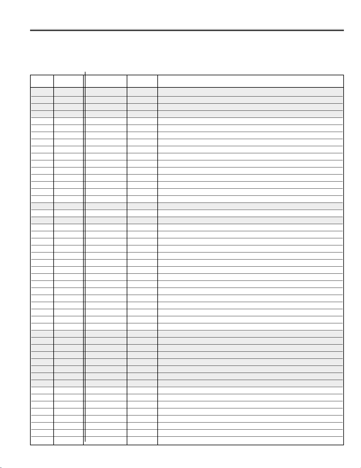
No. Item Initial value Range Description
51 G-YA 00 00,01 G-Y Angle
52 RBGB 10 00~15 R-Y/B-Y Gain Balance
53 RBAG 08→09∗00~15 R-Y/B-Y Angle
54 G-YAN 00 00,01 Difference value of NTSC G-Y Angle
55 RBGBN +4 -8~+7 Difference value of NTSC R-Y/B-Y Gain Balance
56 RBAGN -2→0∗-8~+7 Difference value of NTSC R-Y/B-Y Angle
57 RBADP +2 -8~+7 Difference value of DVD PAL R/B Angle
58 RBDN -2→-5∗-8~+7 Difference value of DVD NTSC R/B Angle
59 RBBDP +2 -8~+7 Difference value of DVD PAL R/B Balance
60 RBBDN 03→00∗00~15 Difference value of DVD NTSC R/B Balance
61 COGV 00→03∗00~03 Coring gain
62 BLKS 01→00∗00~03 BLK. STR. start (W/Defeat)
63 BLKG 00 00~03 BLK. STR. gain
64 BRTA 00 00, 01 BRT. ABL Defeat
65 BRST 00 00, 01 Mid. Stp. Defeat
66 BRTH 00 00~07 Bright. ABL.Threshold
67 WPL 00 00~03 WPL Ope. Point (W/Defeat)
68 YGAM 00 00~03 Y Gamma Start
69 PORW 00 00, 01 AV Mode Pre/Over SW
70 PORS 02 00~03 AV Mode Pre/Over-shoot adjustment
71 RFCO 0 -2~+1 Difference Value of RF Corring Gain
72 PORWN 01 00, 01 RF Pre/Over SW
73 PORSN 03 00~03 RF Pre/Over-shoot adjustment
74 TINT +10 -16~+15 Tint
75 SHRF 00 -16~+15 Difference Value of RF Sharpness
76 SHRFD 00 -16~+15 Difference Value of DVD Sharpness
77 CODP -10 -16~+15 Difference Value of DVD PAL colour
78 CODN 0 -16~+15 Difference Value of DVD NTSC colour
79 RFCOL -7 -16~+15 Difference Value of TV colour
80 TIDN +8 -16~+15 Difference Value of DVD NTSC tint
81 SHRFS 00 -16~+15 Difference Value of S-terminal Sharpness
82 TISN 00 -16~+15 Difference Value of S-terminal NTSC tint
83 COSPN 00 -16~+15 Difference Value of S-terminal colour PAL-N
84 COSPM 00 -16~+15 Difference Value of S-terminal colour PAL-M
85 COSN 00 -16~+15 Difference Value of S-terminal colour NTSC
86 ZOMCOL -6 -16~+15 Difference Value of Colour (Zoom)
87 ZOMCON -6→-8∗-16~+15 Difference Value of Contrast (Zoom)
88 ZOMBRI -6 -16~+15 Difference Value of Brightness (Zoom)
89 TEXC +8 -64~+63 OSD TEXT Contrast
90 AUFL 00 00~01 Auto. Flesh
91 COOP 07 00~07 Colour Killer option
92 Y-APF 01 00, 01 Y-APF Select
93 DEEM 00 00, 01 De-emphasis TC
94 V-LVL 04 00~07 Video Level
95 FMLVL 16 00~1F FM Level
96 TTEST 00 00~07 Trap Test
97 IFOM-S 00 00, 01 Over Modulation SW
98 IFMN-S 00 00, 01 Audio Monitor SW, Monitor or FM
99 IFTRPS 00 00, 01 IC Built-in SIF Trap ON/OFF
100 IFMLVL 136 00~255 Video Level Coarse Adjustment & Modulation Operating Dot Setting
101 VBSW 00 00, 01 VBLK SW
102 FBTS 00 00, 01 FBP Blanking SW
103 HBLKL 05 00~07 H-Blanking Control Left
104 HBLKR 03 00~07 H-Blanking Control Right
105 AFCRF 00 00, 01 Adjustment of AFC Gain & Gate (RF)