-10-
Service Adjustments
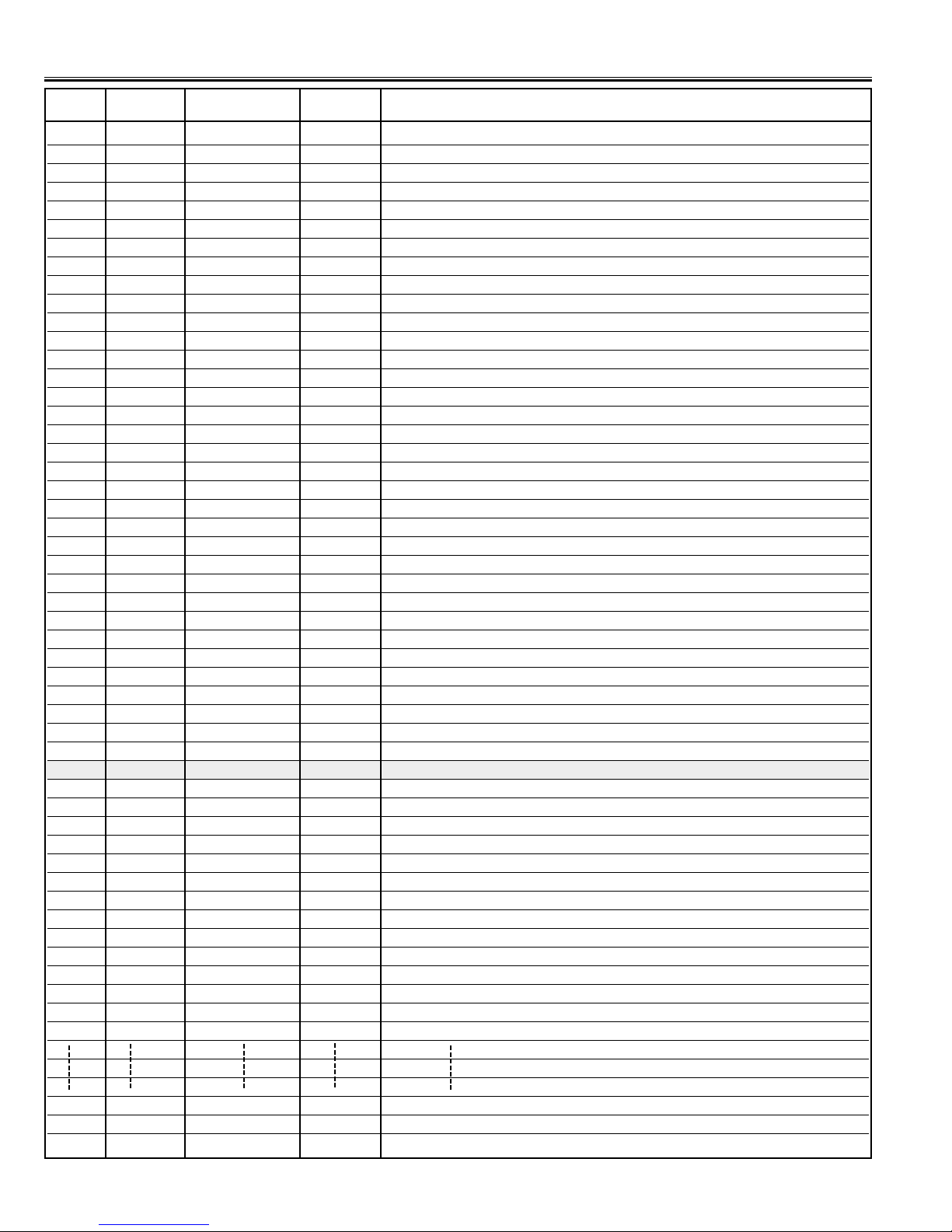
No. Item Initial value Range Description
51 COOP 07 00~07 Colour Killer
52 Y-APF 01 00, 01 Y-APF Select
53 DEEM 00 00, 01 De-emphasis TC
54 V-LVL 04 00~07 Video Level
55 FMLVL 16 00~31 FM Level
56 TTEST 00 00~07 Trap Test
57 IFOM-S 00 00, 01 Over Mod. SW
58 IFMN-S 00 00, 01 Audio Monitor SW, Monitor/FM
59 IFTRPS 01 00, 01 IC Built-in SIF Trap ON/OFF
60 IFMLVL 136 00~255 Video Level Coarse Adjustment & Mod. Operating Dot Setting
61 VBSW 00 00, 01 VBLK SW
62 FBTS 00 00, 01 FBP Blanking SW
63 HBLKL 06 00~07 H-Blanking Control Left
64 HBLKR 04 00~07 H-Blanking Control Right
65 AFCRF 00 00, 01 Adjustment of AFC Gain & Gate (RF)
66 VSURF 00 00, 01 Adjustment of Vertical Sync. Separation Sensitivity (RF)
67 CDMRF 00 00~07 Vertical Count Down Loop Adjustment (RF)
68 AFCAV 00→01* 00, 01 Adjustment of AFC Gain & Gate (AV)
69 VSUAV 00 00, 01 Adjustment of Vertical Sync. Separation Sensitivity (AV)
70 CDMAV 00 00~07 Vertical Count Down Loop Adjustment (AV)
71 HLK-T 00 00, 01 H-lock, V-Det. (RF)
72 HLK-V 00 00, 01 H-lock, V-Det. (AV)
73 VCO-SW 00 00, 01 C. VCO Adjustment SW
74 VCOADJ 03 00~03 C. VCO Adjustment
75 GRAY 00 00, 01 Gray Mode
76 CROSS 00 00~03 Cross Black/White
77 HL-SW 01 00, 01 Half Tone ON/OFF
78 HL-TON 00 00~03 Half Tone Level
79 AVNCON 64 00~127 Contrast (No Signal in AV)
80 AVNBRI 64 00~127 Brightness (No Signal in AV)
81 POMT 12→08* 00~127 Power Mute Time
82 CHMT 12→05* 00~31 Channel Mute Time
83 SYST 03 00~255 System-N
84 RELAY 80→20* 00~255 Power Relay Time
85 CCD 26→31* 00~31 Horizontal Remark Position Compensation Register
86 TVAVTM 00 00~255 AV/TV Mute Time
300 R00 FF→93* 00~FF ROM CORRECTION
301 R01 FF→0E* 00~FF ROM CORRECTION
302 R02 FF→00* 00~FF ROM CORRECTION
303 R03 FF→00* 00~FF ROM CORRECTION
304 R04 FF→01* 00~FF ROM CORRECTION
305 R05 FF→00* 00~FF ROM CORRECTION
306 R06 FF→00* 00~FF ROM CORRECTION
307 R07 FF→00* 00~FF ROM CORRECTION
308 R08 FF→21* 00~FF ROM CORRECTION
309 R09 FF→95* 00~FF ROM CORRECTION
310 R10 FF→50* 00~FF ROM CORRECTION
311 R12 FF→00* 00~FF ROM CORRECTION
312 R13 FF→00* 00~FF ROM CORRECTION
370 R72 FF→00* 00~FF ROM CORRECTION
371 R72 FF→00* 00~FF ROM CORRECTION
372 R72 FF→A2* 00~FF ROM CORRECTION