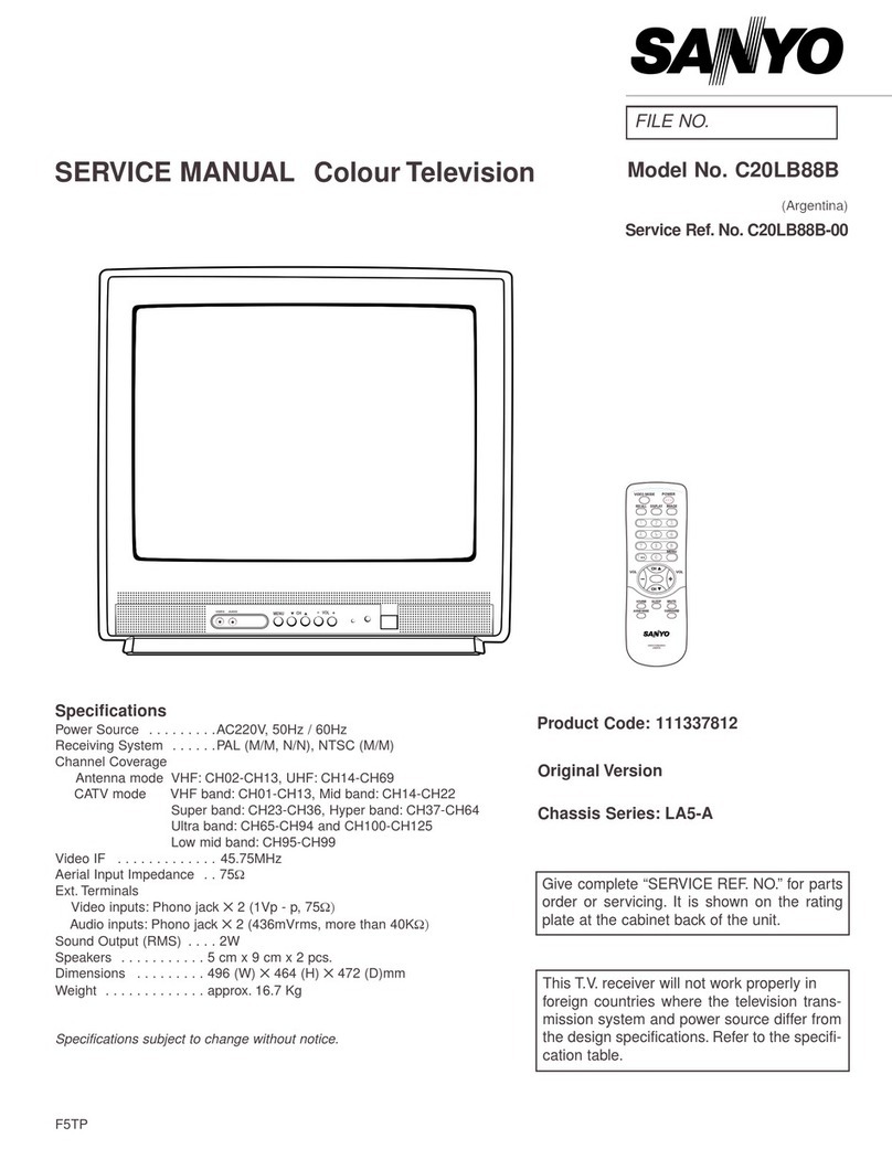
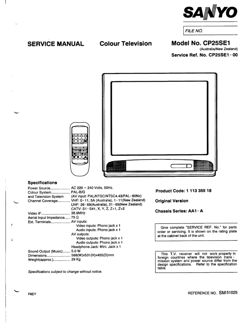
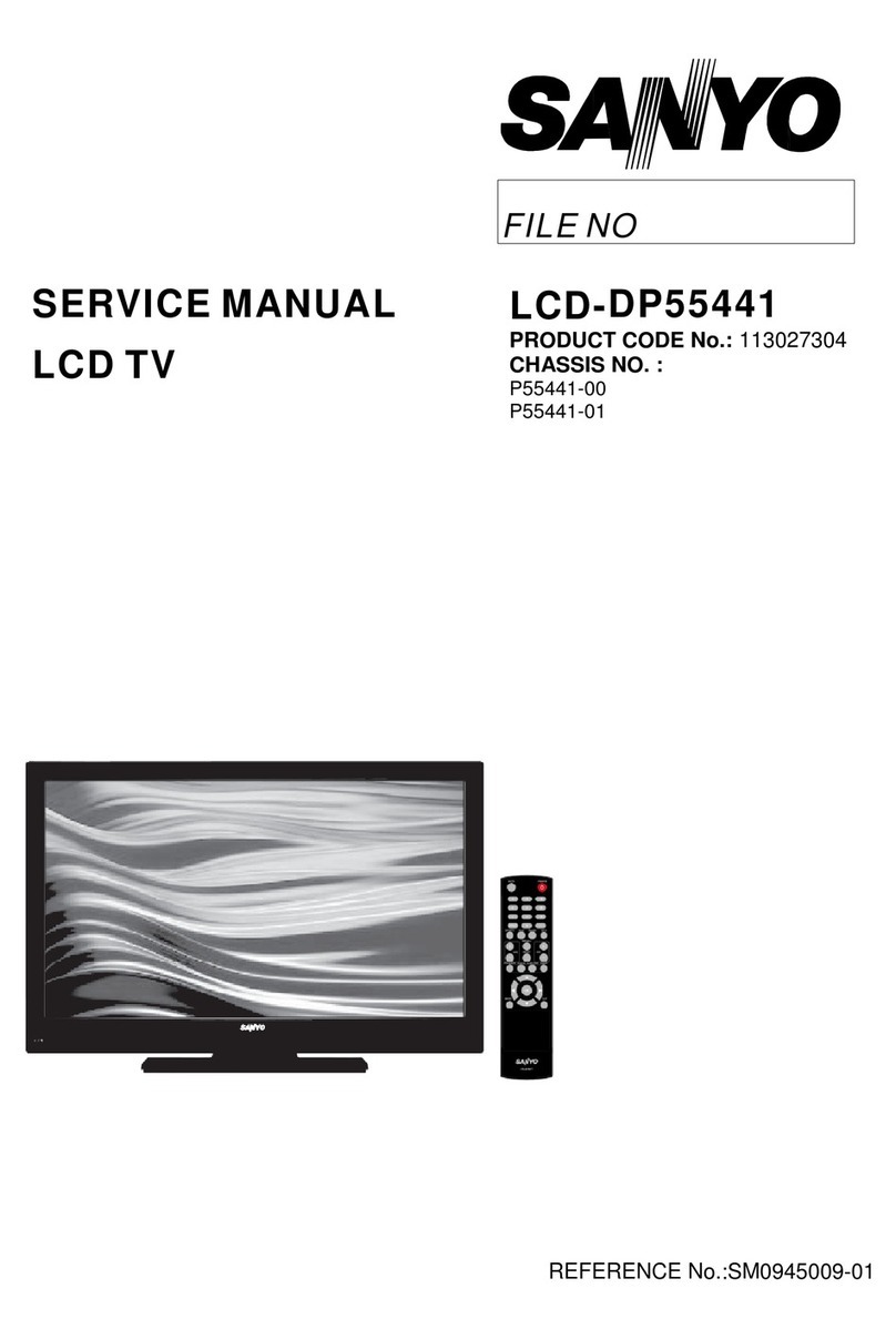
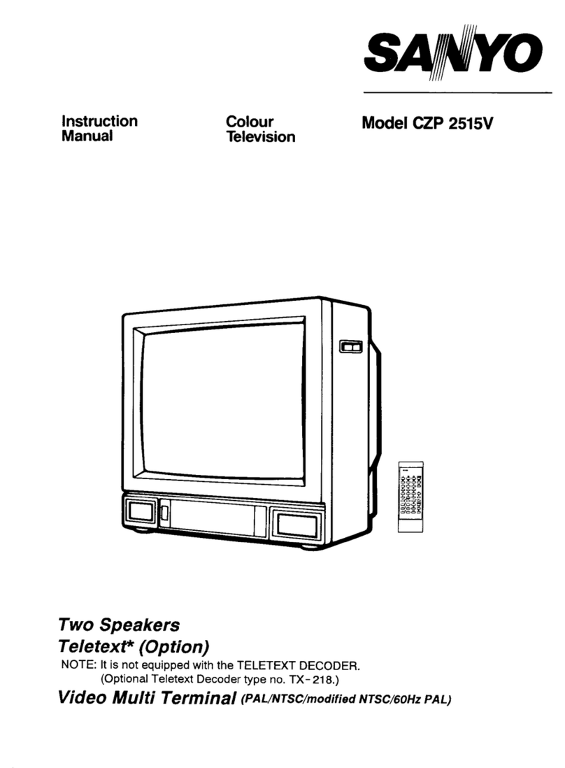
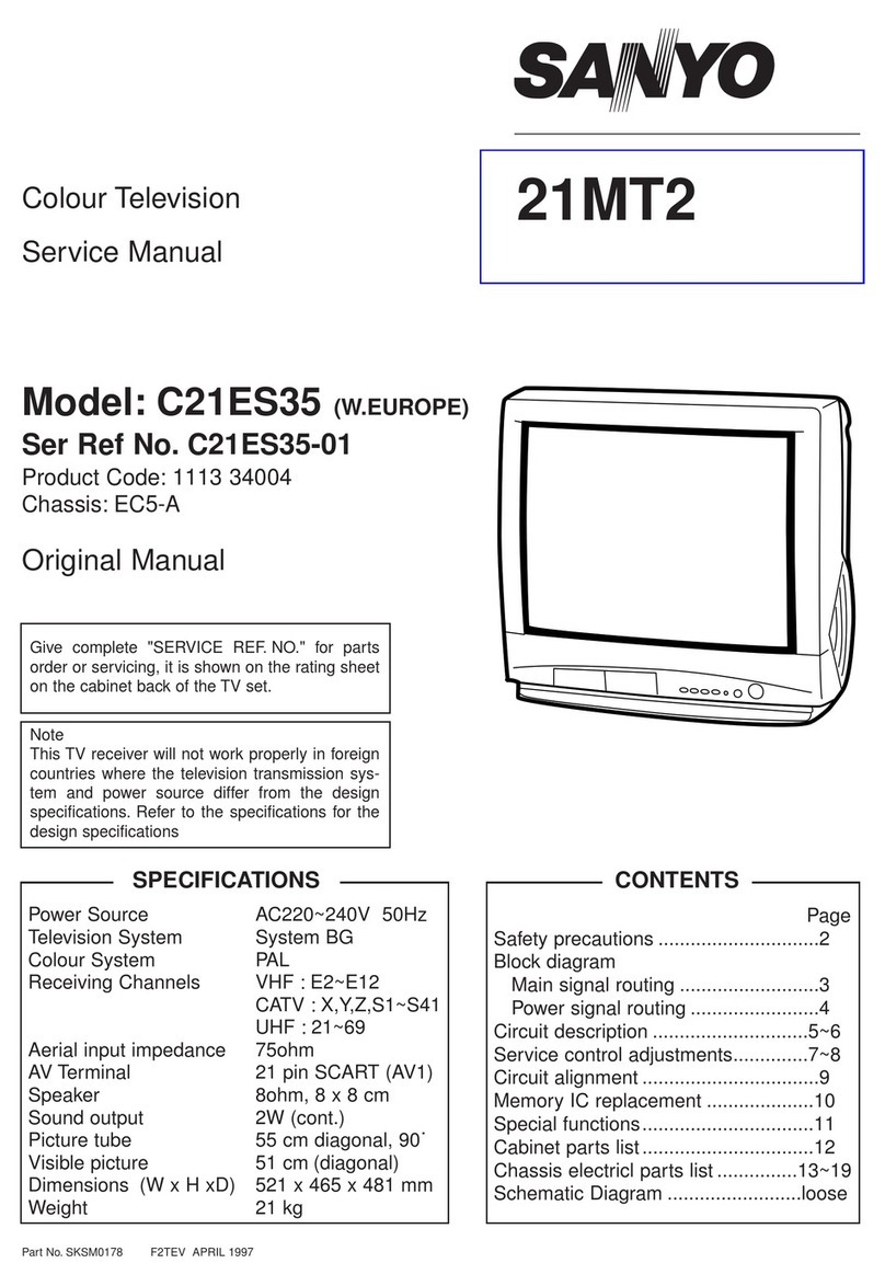
Sanyo CP29EF3 User manual

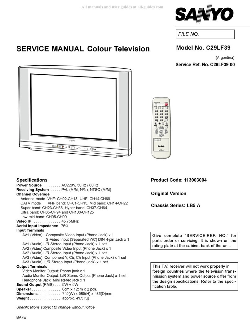
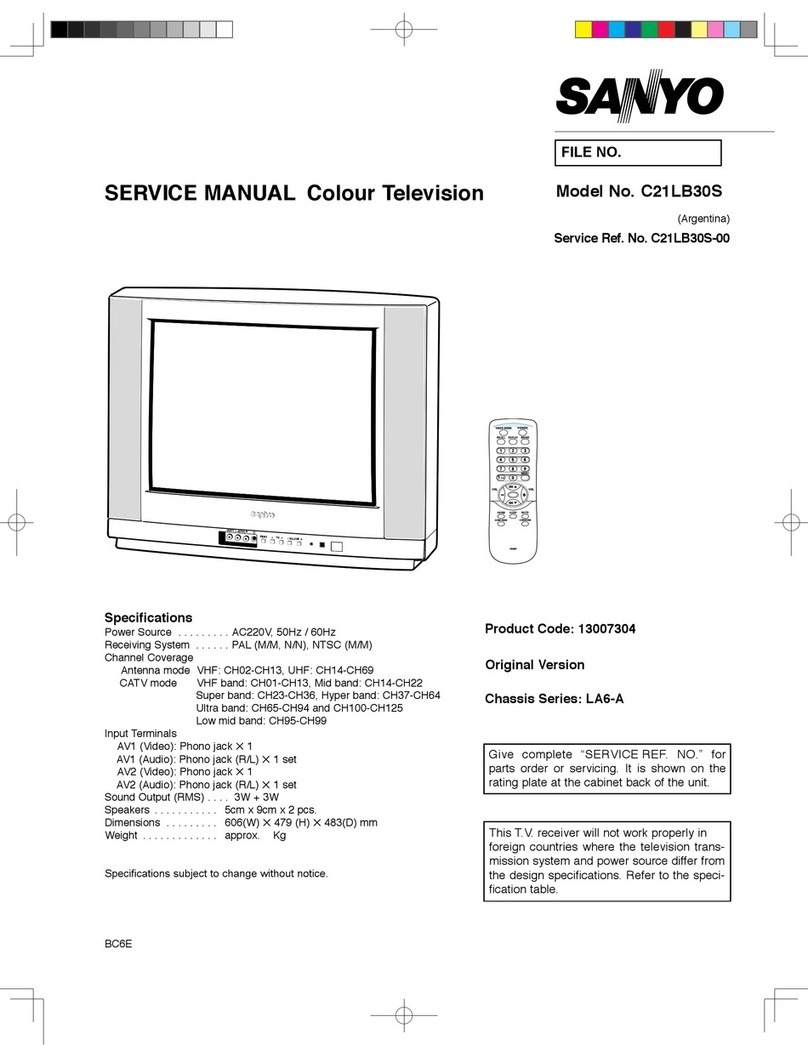
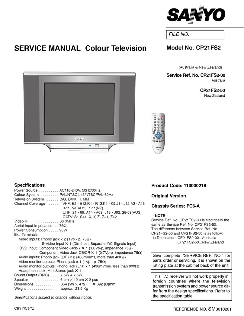
SERVICE MANUAL Colour Television
Specifications
Power Source . . . . . . . .AC110
-
240V, 50/60Hz.
Colour System . . . . . . . .PAL, SECAM, NTSC4.43, NTSC, PAL 60Hz
Television System . . . . .B/G, D/KK’, I, M/M
Channel Coverage . . . . .VHF: E2-E12, R1-R12, K1-K9, J1-J12, A2-A13, 1-11
UHF: 21-69, A14-A69, J13-J62
CATV: S1-S41, X, Y, Z, Z+1, Z+2
Video IF . . . . . . . . . . . . . .38.0 MHz
Aerial Input Impedance .75Ω
Ext. Terminals
Video inputs: Phono jack 2 (1.0Vp
-
p, impedance 75Ω)
S-Video Input 1 (Din 4 pin, Separate Y/C Signals Input)
DVD Input: Component Video Jack-Y 1 (1.0Vp-p, impedance 75Ω)
Component Video Jack CB/CR 1 (0.7Vp-p, impedance 75Ω)
Audio inputs: Phono jack (R/L) 3 (436mVrms, impedance more than 40KΩ)
Video monitor output: Phono jack 1 (1.0Vp
-
p, 75Ω)
Audio monitor outputs: Phono jack(R/L) 1(436mVrms, Impedance less than
600Ω)
Headphone jack: Mini Stereo jack 1
Speaker . . . . . . . . . . . . . . 6 cm 12 cm 2 pcs.
Sound Output . . . . . . . . . 10W + 10W (RMS)
Dimensions . . . . . . . . . . . 750 (W) 581 (H) 497 (D)mm
Weight . . . . . . . . . . . . . . . approx. 47.5 Kg
Specifications subject to change without notice
Original Version
Chassis Series: FB1-A
C7GZ
FILE NO.
Model No. CP29EF3
Service Ref. No. CP29EF3-00
(New Zealand)
Give complete “SERVICE REF. NO.” for parts
order or servicing. It is shown on the rating plate
at the cabinet back of the unit.
This T.V. receiver will not work properly in
foreign countries where the television
transmission system and power source dif-
fer from the design specifications. Refer to
the specification table.
Product Code: 111379518
REFERENCE NO. SM3010109
TV/AV MENU - + CH
POWER
123
456
789
0
TV/AV
TIMER
?
x
-/--
SWAP
SOUND
MENU
BASS
TXT/TV
S. SYS
SURROUND
PICTURE
CH
CH
A B
.
PP
i
JXPSB
SM_29-C7GZ(NZ) 9/8/05 4:25 PM Page 1

Contents
-2-
Safety Notice . . . . . . . . . . . . . . . . . . . . . . . . . . . . . . . . . . . . . . . . . . . . . . . 2
Chassis Block Diagram . . . . . . . . . . . . . . . . . . . . . . . . . . . . . . . . . . . . . . . 3
IC Block Diagrams . . . . . . . . . . . . . . . . . . . . . . . . . . . . . . . . . . . . . . . . . 4-6
CPU Port Functions . . . . . . . . . . . . . . . . . . . . . . . . . . . . . . . . . . . . . . . . 7-8
Option Setting . . . . . . . . . . . . . . . . . . . . . . . . . . . . . . . . . . . . . . . . . . . . . . 9
Service Adjustments with Replacing Memory IC (IC802) . . . . . . . . . . 10-14
Dealer Mode . . . . . . . . . . . . . . . . . . . . . . . . . . . . . . . . . . . . . . . . . . . . . . .15
Adjustment . . . . . . . . . . . . . . . . . . . . . . . . . . . . . . . . . . . . . . . . . . . . . .16-17
Purity and Convergence Adjustment . . . . . . . . . . . . . . . . . . . . . . . . . 18-19
Mechanical Disassembly . . . . . . . . . . . . . . . . . . . . . . . . . . . . . . . . . . . . . 20
Protection Circuit . . . . . . . . . . . . . . . . . . . . . . . . . . . . . . . . . . . . . . . . . . . 20
Cabinet Parts List . . . . . . . . . . . . . . . . . . . . . . . . . . . . . . . . . . . . . . . . . . 21
Chassis Electrical Parts List . . . . . . . . . . . . . . . . . . . . . . . . . . . . . . . . 22-30
Component Locations . . . . . . . . . . . . . . . . . . . . . . . . . . . . . . . . . . . . . 31-33
Voltages and Waveforms Charts. . . . . . . . . . . . . . . . . . . . . . . . . . . . . 34-35
Safety Notice
SAFETY PRECAUTIONS
1: An isolation transformer should be connected in the
power line between the receiver and the AC line
when a service is performed on the primary of the
converter transformer of the set.
2: Comply with all caution and safety-related notes pro-
vided on the cabinet back, inside the cabinet, on the
chassis or the picture tube.
3: When replacing a chassis in the cabinet, always be
certain that all the protective devices are installed
properly, such as, control knobs, adjustment covers
or shields, barriers, isolation resistor-capacitor net-
works etc.. Before returning any television to the
customer, the service technician must be sure that
it is completely safe to operate without danger of
electrical shock.
X-RADIATION PRECAUTION
The primary source of X-RADIATION in television receiver is the picture tube. The picture tube is specially con-
structed to limit X-RADIATION emissions. For continued X-RADIATION protection, the replacement tube must be
the same type as the original including suffix letter. Excessive high voltage may produce potentially hazardous X
- RADIATION. To avoid such hazards, the high voltage must be maintained within specified limit. Refer to this
service manual, high voltage adjustment for specific high voltage limit. If high voltage exceeds specified limits,
take necessary corrective action. Carefully follow the instructions for + B1 volt power supply adjustment, and high
voltage check to maintain the high voltage within the specified limits.
PRODUCT SAFETY NOTICE
Product safety should be considered when a component replacement is made in any area of a receiver.
Components indicated by mark in the parts list and the schematic diagram designate components in which
safety can be of special significance. It is particularly recommended that only parts designated on the parts list
in this manual be used for component replacement designated by mark . No deviations from resistance
wattage or voltage ratings may be made for replacement items designated by mark .
SM_29-C7GZ(NZ) 9/8/05 4:25 PM Page 2

TUNER
VIDEO
L/R
INPUT-1 INPUT-2
INPUT-3
MONITOR
OUT
Y-IN
Cb-IN
Cr-IN
L/R
VIDEO
VIDEO
L/R
L/R
Y/C
VIF/SIF
IC201
PROCESSOR
IC001
AUDIO AMP.
IC1401
WOOFER AMP.
KEY SW RC
RECEIVER LED
H-PHONE SPEAKER WOOFER
IC802
EEPROM
IC701
TRIPLE
VIDEO
OUTPUT
AMP
IC501
VERTICAL
T431
H-DRIVE
TRANS
Q431
H-DRIVE
Q901
CRT
T471
FBT
Q432
H-OUT
PCC
CIRCUIT
-3-
Chassis Block Diagrams
IC1401<Woofer Pre-Amp. IC> is not used
SM_29-C7GZ(NZ) 9/8/05 4:25 PM Page 3

IC Block Diagrams
-4-
11
12
COLOUR SYSTEM OPTION INPUT
KEY SWITCH IN KEY
SWITCH
SCL
2
1
106
SDA
POWER ON/OFF
PHOTO COUPLE
(ON=HIGH, OFF=LOW)
IC201
UOCIII
QXXAVC534M
18
17
127
9998
7
6
112
99
26
33
DEFLECTION
CIRCUIT
HORIZ. SYNC IN (ACTIVE=LOW)
VERT. SYNC IN (ACTIVE=LOW)
POWER PROTECT IN
(POWER ERROR=LOW) POWER CIRCUIT
etc.
SCL
SDA
IC802
MEMORY
OSC
X801
32.768KHz CPU OSC OUT
CPU OSC IN
LED ON-TIMER LED OUT (ON TIMER ON=Low)
RC SIGNAL IN
(ACTIVE=HIGH)
RC PRE-AMP.
9
122
SOUND MUTE
IC001
AUDIO AMP.
VIF-M OUTPUT (HIGH=NTSC, LOW=OTHER)
A101
F/S TUNER
RESET INPUT (RESET=LOW) 13
VIDEO SELECTOR
(LOW=AV1, H=AV2)
56
SECAM KILLER INPUT (HIGH=SECAM)
IC1201
VIDEO SELECTOR 2
16
BILINGUAL OUTPUT (LOW=S-1, HIGH=S-2)
IC3701
AUDIO CONTROL/
SURROUND
10
13 14
5
4
System Control
QXXAVC534C7JAS
SM_29-C7GZ(NZ) 9/8/05 4:25 PM Page 4

-5-
IC201 < CPU/IF/Video/Chroma/Def.> QXXAVC534C7JAS
IC Block Diagrams
SWITCH
QSS SOUND IF
AGC
QSS MIXER
AM DEMODULATOR
QSSO/AMOUT
REFO SSIF
SIFIN/DVBIN
DVBO/IFVO/
FMRO
DVBO/FMRO
AGCOUT
VIFIN
IFVO/SVO/
CVBSI
YSYNC
CVBS2/Y2
CVBS3/Y3
CVBS4/Y4
C2/C3
C4
CVBSO/PIP
VISION IF/AGC/AFC
PLL DEMOD.
SOUND TRAP
GROUP DELAY
VIDEO AMP.
VIDEO SWITCH
VIDEO IDENT.
VIDEO FILTERS
H/V SYNC SEP.
H.OSC. + PLL
2nd LOOP
H-SHIFT
H.DRIVE
HOUT
H/V
Y
C
SOUND PLL
DEEMPHASIS
PAL/SECAM/NTSC
DECODER
DIGITAL
2H/4H
COMB FILTER
Y DELAY ADJ.
VERTICAL
& EAST-WEST
GEOMETRY
V-DRIVE
EWD EHTO BL
R/PR
G/Y
B/PB
B/PB
SWO1BL
Vo Uo Ui ViYo Yi
G/Y R/PR
RGB/YPRPBINSERT
YUV INTERFACE
BASE-BAND
DELAY LINE
A/D CONVERTER
ALL-STANDARD
STEREO
DECODER AM
SCART/CINCH IN/OUT
AUDIO SELECT
ADC/DAC
12S
AUDIO CONTROL
VOLUME
TREBBLE/BASS
FEATURES
DACS
LS-OUT HP-OUT
LR LR
RDS
I/OS
µ-PROCESSOR AND TELETEXT DECODER
DIGITAL SIGNAL PROCESSING FEATURES
SCAVEM
ON TEXT
YUV IN/OUT
PEAKING
SCAN VELOCITY
MODULATION
U/V DELAY
YUV
CON.
BRI
BL RGBCR
RGB CONTROL
OSD/TEXT INSERT
CONTR/BRIGHTN
CCC
WHITE-P.ADJ.
RO
GO
BO
BCLIN
BLKIN
SVM
RGB MATRIX
BLUE STRETCH
BLACK STRETCH
GAMMA CONTROL
SAT
SKIN TONE
U/V TINT
SATURATION
(CVBSX/YX)(CX)
REF
29
30
39
43
44
31
24
25
48
73
55
58
59
51
64
52
67 22 23 32
65
84
83
87
86
85
63
6261
60
78 79 80 76
33
SM_29-C7GZ(NZ) 9/8/05 4:25 PM Page 5

-6-
IC Block Diagrams
IC001 < Audio AMP.> TDA8947J/N3
1
2
3MUTE
REFERENCES
NON INVERTING INPUT (1)
INVERTING INPUT (1)
SUR/MUTING
TURN ON
AND OFF
9
5
10
8
4
6
Vcc
NON INVERTING INPUT (2)
INVERTING INPUT (2)
L
R
-
+
-
+
GND
RF I 27K
RF I 27K
SC
PROTECTION
Tj
TH
PROTECTION
OUTPUT-L
OUTPUT-R
IC501 < Vertical Output > LA78041
Thermal
Protection
-
+AMP
Pump
Up
1
INVERTING
INPUT
2
Vcc
3
PUMP UP
OUT
4
GND
5
Ver. OUTPUT
6
OUTPUT
STAGE Vcc
7
NON INV.
INPUT
SM_29-C7GZ(NZ) 9/8/05 4:25 PM Page 6

-7-
CPU Port Functions
Pin No. Function Name Function
1VSSP2 Ground
2VSSC4 Ground
3VDDC4 Digital supply to SDACs (1.8V)
4VDDA3(3.3V) Supply (3.3V)
5VREF_POS_LSL Positive reference voltage SDAC (3.3V)
6VREF_NEG_LSL+HPL Negative reference voltage SDAC (0 V)
7VREF_POS_LSR+HPR Positive reference voltage SDAC (3.3 V)
8VREF_NEG_HPL+HPR Negative reference voltage SDAC (0 V)
9VREF_POS_HPR Positive reference voltage SDAC (3.3V)
10 XTALIN Crystal oscillator input
11 XTALOUT Crystal oscillator output
12 VSSA1 Ground
13 VGUARD/SWIO V-guard input / I/O switch
14 DECDIG Decoupling digital supply
15 VP1 1st supply voltage TV-processor (+5 V)
16 PH2LF Phase-2 filter
17 PH1LF Phase-1 filter
18 GND1 Ground 1 for TV-processor
19 SECPLL SECAM PLL decoupling
20 DECBG Bandgap decoupling
21 EWD/AVL (1) East-West drive output orAVL capacitor
22 VDRB Vertical drive B output
23 VDRA Vertical drive A output
24 VIFIN1 IF Input 1
25 VIFIN2 IF Input 2
26 VSC Vertical sawtooth capacitor
27 IREF Reference current input
28 GNDIF Ground connection for IF amplifier
29 SIFIN1/DVBIN1 (2) SIF input 1 / DVB input 1
30 SIFIN2/DVBIN2 (2) SIF input 2 / DVB input 2
31 AGCOUT Tuner AGC output
32 EHTO EHT/overvoltage protection input
33 AVL/SWO/SSIF/ Automatic Volume Levelling / swith
REFO/REFIN (2)(3) output / sound IF input / subcarier
reference output / external reference
signal input for I signal mixer for
DVB operation
34 AUDIOIN5L Audio-5 input (left signal)
35 AUDIOIN5R Audio-5 input (right signal)
36 AUDOUTSL Audio output for SCART/CINCH (left signal)
37 AUDOUTSR Audiooutput for SCART/CINCH(rightsignal)
38 DECSDEM Decoupling sound demodulator
39 QSSO/AMOUT QSS intercarrier output / AM output
/AUDEEM (2) / deemphasis (front-end audio out)
40 GND2 Ground 2 for TV processor
41 PLLIF IF-PLL loop filter
42 SIFAGC/DVBAGC(2) AGC sound IF / internal-external
AGC for DVB applications
Pin No. Function Name Function
43 DVBO/IFVO/FMRO (2) Digital Video Broadcast output / IF
video output / FM radio output
44 DVBO/FMRO (2) Digital Video Broadcast output / FM
radio output
45 VCC8V 8 Volt supply for audio switches
46 AGC2SIF AGC capacitor second sound IF
47 VP2 2nd supply voltage TV processor (+5 V)
48 IFVO/SVO/CVBSI (2) IF video output / selected CVBS
output / CVBS input
49 AUDIOIN4L Audio-4 input (left signal)
50 AUDIOIN4R Audio-4 input (right signal)
51 CVBS4/Y4 CVBS2/Y4 input
52 C4 Chroma-4 input
53 AUDIOIN2L/SSIF (3) Audio 2 input (left signal) / sound IF
input
54 AUDIOIN2R Audio 2 input (right signal)
55 CVBS2/Y2 CVBS2/Y2 input
56 AUDIOIN3L Audio 3 input (left signal)
57 AUDIOIN3R Audio 3 input (right signal)
58 CVBS3/Y3 CVBS3/Y3 input
59 C2/C3 Chroma-2/3 input
60 AUDOUTLSL Audio output for audio power ampli-
fier (left signal)
61 AUDOUTLSR Audio output for audio power ampli-
fier (left signal)
62 AUDOUTHPL Audio output for headphone channel
(left signal)
63 AUDOUTHPR Audio output for headphone channel
(Right signal)
64 CVBSO/PIP CVBS / PIP output
65 SVM Scan velocity modulation output
66 FBISO/CSY Flyback input/sandcastle output or
composite H/V timing output
67 HOUT Horizontal output
68 VSScomb Ground connection for comb filter
69 VDDcomb Supply voltage for comb filter (5V)
70 VIN (R/PRIN2/CX) V-input for YUV interface (2nd R
input / PR input or Cxinput)
71 UIN (B/PBIN2) U-input for YUV interface (2nd B
input / PB input)
72 YIN(G/YIN2/CVBS-Yx) Y-input for YUV interface (2nd G
input / Y input or CVBS/Yx input)
73 YSYNC Y-input for sync separator
74 YOUT Y-output (for YUV interface)
75 UOUT (INSSW2) U-output for YUV interface (2nd
RGB / YPBPRinsertation input)
76 VOUT (SW01) V-output for YUV interface (general
purpose switch output)
77 INSSW3 3rd RGB / YPBPRinsertion input
78 R/PRIN3 3rd R input / PRinput
SM_29-C7GZ(NZ) 9/8/05 4:25 PM Page 7

-8-
Pin No. Function Name Function
79 G/YIN3 3rd G input / Y input
80 B/PBIN3 3rd B input / PBinput
81 GND3 Ground 3 for TV-processor
82 VP3 3rd supply for TV processor (5V)
83 BCLIN Beam current limiter input
84 BKLIN Black current input
85 RO Red output
86 GO Green output
87 BO Blue output
88 VDDA1 Analog supply for TCG µ-Controller
and digital supply for TV-processor
(+3.3V)
89 VREFAD_NEG Negative reference voltage (0 V)
90 VREFAD_POS Positive reference voltage (3.3 V)
91 VREFAD Reference voltage for audio ADCs
(3.3/2 V)
92 GNDA Ground
93 VDDA(1.8V) Analogue supply for audio ADCs
(1.8V)
94 VDDA2(3.3) Supply voltage SDAC (3.3 V)
95 VSSadc Ground for video ADC and PLL
96 VDDadc(1.8) Supply voltage video ADC and PLL
97 INT0/P0.5 External interrupt 0 or port 0.5 (4 mA
current sinking capability for direct
drive of LEDs)
98 P1.0/INT1 Port 1.0 or external interupt 1
99 P1.1/T0 Port 1.1 or Counter/Timer 0 input
100 VDDC2 Digital supply to core (1.8 V)
101 VSSC2 Ground
102 P0.4/I2SWS Port 0.4 or I2S word select
103 P0.3/I2SCLK Port 0.3 or I2S clock
104 P0.2/I2SDO2 Port 0.2 or I2S digital output 2
105 P0.1/I2SDo1 Port 0.1 or I2S digital output 1
106 P0.0/I2SDI1/O Port 0.0 or I2S digital input 1 or I2S
digital output
107 P1.3/T1 Port 1.3 or Counter/Timer 1 input
108 P1.6/SCL Port 1.6 or I2C-bus clock line
109 P1.7/SDA Port 1.7 or I2C-bus data line
110 VDDP(3.3V) Supply to periphery and on-chip voltage
regulator (3.3V)
111 P2.0/TPWM Port 2.0 or Tuning PWM output
112 P2.1/PWM0 Port 2.1 or PWM0 output
113 P2.2/PWM1 Port 2.2 or PWM1 output
114 P2.3/PWM2 Port 2.3 or PWM2 output
115 P3.0/ADC0 Port 3.0 or ADC0 input
116 P3.1/ADC1 Port 3.1 or ADC1 input
117 VDDC1 Digital supply to core (+1.8V)
118 DECV1V8 Decoupling 1.8V supply
119 P3.2/ADC2 Port 3.2 or ADC2 input
Pin No. Function Name Function
120 P3.3/ADC3 Port 3.3 or ADC3 input
121 VSSC/P Digital ground for µ-Controller core
and periphery
122 P2.4/PWM3 Port 2.4 or PWM3 output
123 P2.5/PWM4 Port 2.5 or PWM4 output
124 VDDC3 Digital supply to core (1.8V)
125 VSSC3 Ground
126 P1.2/INT2 Port 1.2 or external interrupt 2
127 P1.4/RX Port 1.4 or UART bus
128 P1.5/TX Port 1.5 or UART bus
CPU Port Functions
SM_29-C7GZ(NZ) 9/8/05 4:25 PM Page 8

-9-
MENU
Option Setting
After replacing the Memory IC (IC802)
The memory IC (IC802), stores the option data of TV set and service adjustments data for each circuit, therefore,
when the memory IC is replaced, it should be programmed to the following settings and “ SERVICE ADJUSTMENT”
on pages 15 to 16.
1) To enter to the Option Mode
Press and hold the MENU on the remote control and Programme down button (CH)on the front panel of
the TV. The option window will appear on the screen.
- + CH
PLUG & PLAY
WELCOME TEXT
AUTO VOLUME
SURROUND
WOOFER
TEXT NO SIGNAL
AFC
MPP
ON
OFF
OFF
ON
ON
ON
ON
OFF
OPTION
HOTEL MODE
OFF
Option Mode
2) To set the Option Mode
Select the desired option item by pressing the Programme down or up button.
To switch the option mode, use the Level up or down button.
The data which is set in the option mode is stored into the memory IC automatically.
The following table shows the available option items and default setting mode.
Option Mode Mode Description & Note
PLUG & PLAY ON or OFF Plug & Play mode, default “ON”
WELCOME TEXT ON or OFF Display message when first set up, default “OFF”
AUTO VOLUME ON or OFF Auto volume, default “OFF”
SURROUND ON or OFF Default “ON”
WOOFER ON or OFF Default “ON”
TEXT NO SIGNAL ON or OFF When no received signal, execution, default “ON”
AFC ON or OFF Automatic Frequency Control (AFC) available, default “ON”
MPP ON or OFF MPP available, devault “ON”
3) Exit from the Service Mode
Press the Menu button or turn off the TV set by using the mains switch.
SM_29-C7GZ(NZ) 9/8/05 4:25 PM Page 9

-10-
Service Adjustments with Replacing Memory IC(IC802)
Note: The CPU (IC201) and memory IC (IC802) store the service adjustments data and controls data for each
circuit.When the Memory IC(IC802) is replaced, some of the service adjustments should be readjusted to
obtain the best performance. The necessary service adjustments are carried out by using the RC handset.
Please set up the TV set with following steps [1] to [2].
[1] Initializing Procedure
1. Put a new memory IC.
2. Turn on the TV set.
3. Enter to the Service Mode as explanation on next page. Select “002 INIT TV 0” mode, then change to “1” by
pressing Volume + button on Remote Control.
4. When initialised the memory IC are completed, TV set will in stand by mode, all of the setting data (option data and
service adjustment data) stored in the IC are reset to the default value. It is necessary to set the option settings and
readjust the service adjustments (listed on page 11-13) and to re-tune all the channels.
This completes the initialization of memory IC.
Following shows the initialized contents of memory data by this procedure.
- Plug & Play : No executed
- Inhibit Data : Cancelled
- Ch Skip Data : Cancelled
- Swap Data : Cancelled
- Surround : OFF
- Woofer : OFF
- Sound Volume Data : 12/63 steps
- Bass Data : 32/63 steps
- Treble Data : 32/63 Steps
- Colour System : AUTO
- Sound System : BG
[2] Required Service Adjustments
Readjust the following service adjustments.
Adjustments Service Mode No. & Item
Vertical slope Item 015, Vert. Slope
Vertical shift Item 016, Vert. Shift
Vertical amplitude Item 017, Vert. Ampl.
Vertical-S correction Item 018, S-Corr.
EW width Item 021, EW Width
Horizontal shift Item 022, Hor. Shift
- - - - - -
Further adjustment please refer to page 12 ~ 14.
SM_29-C7GZ(NZ) 9/8/05 4:25 PM Page 10

-11-
Service Adjustments with Replacing Memory IC(IC802)
1) To enter to the Service Mode
1. Press and hold the Volume + button on the front of TV set and press the Menu button on the Remote Control.
3) Exit from the Service Mode
Press the Menu button or turn off the TV set by using the mains switch.
Adjustment Data
Item No.
SERVICE
001 FB1A 0.92
ZOOM 50HZ
020 V.LINEARITY 39
00111010 00000000
01010000 10001100
10000001 00001010
00011010 00001010
Example
Display for [V.Linearity] Vertical Linearity adjustment
2. Press the Programme up / down button to select the mode required. Then press the Volume + button to
adjust.
- + CH
MENU
MENU
CH
0102030405....96.. 9695949392....01..
Read Status Item
Display for Software Version Information
CH
SM_29-C7GZ(NZ) 9/8/05 4:25 PM Page 11

-12-
DATA INITIAL
No. ITEM RANGE SETUP DESCRIPTION
DATA
01 FB1A x,y Software version information
02 Init TV 0 -1 0 Initialise NVM
03 ISP Mode 0 - 1 0 Set the TV in ISP mode
04 PWT - 00001 Power on time
05 DDLE 0 - 1 1
06 Cut Off 0 - 63 10 Cut off
07 VSD - - Vertical scan disable (1 line adj.)
08 VG2 0 - 1 1 Adjustment Vg2 voltage
10 DCXO 0 - 127 48 DXCO adjustment
11 DXCOAuto 0 0 Automatic DXCO adjustment
(Adjust in NICAM)
12 TUBE-TYPE 0 - 1 1 Picture tube type (0=16:9, 1=4:3)
13 TRACK. MODE 0 - 1 0 Track. Mode (HCO)
14 VERT. ZOOM 0 - 63 25 Vertical Zoom
15 VERT. SLOPE 0 - 63 36 Vertical Slope
16 VERT. SHIFT 0 - 63 33 Vertical Shift
17 VERT. AMPL. 0 - 63 47 Vertical Amplitude
18 S-CORR 0 - 63 29 S-Correction
19 V.LIN.CTRL 0 - 2 0 Vertical Linearity Control
20 V. LINEARITY 0 - 63 35 Vertical Linearity
21 EW WIDTH 0 - 63 36 East West Width
22 HOR. SHIFT 0 - 63 38 Horizontal Shift
23 EWPARABOLA 0 - 63 28 East West Parabola Width
24 TRAPEZIUM 0 - 63 11 East West Trapezium
25 UC PARABOLA 0 - 63 42 East West Upper Corner Parabola
26 LC PARABOLA 0 - 63 53 East West Lower Corner Parabola
27 HOR. BOW 0 - 63 37 Horizontal Bow
28 PARALLEL 0 - 63 30 Horizontal Parallelogram
29 VERT. SCROLL 0 - 63 32 Vertical Scroll
30 H BLK SW 0 - 1 1 R G B Blanking Mode
31 WBF 0 - 15 6 Timing of wide blankingfront(WBF)
32 WBR 0 - 15 9 Timing of wide blanking rear(WBR)
33 OSVE 0 - 1 0 Black current measuring lines in overscan
34 EVB 0 - 1 1 Extended Vertical Blanking
35 I01 TRACK MODE. 0 - 1 0 Track Mode(HCO)
36 I02 VERT.ZOOM 0 - 255 3 Vertical Zoom
37 I03 VERT.SLOPE 0 - 255 0 Vertival Slope
38 I04 VERT.SHIFT 0 - 255 2 Vertical Shift
39 I05 VERT.AMPL. 0 - 255 255 Vertical Amplitudo
40 I06 S-CORR 0 - 255 0 S-Correction
41 I07 V.LIN.CTRL. 0 - 255 0 Vertical Linearity Control
42 I08V.LINEARITY 0 - 255 5 Vertical Linearity
43 I09 EW WIDTH 0 - 255 255 East West Width
44 I10 HOR. SHIFT 0 - 255 5 Horizontal Shift
45 I11EWPARABOLA 0 - 255 1 East West Parabola Width
Following table shows the initial values which have been stored in the CPU ROM, and items for the service adjustments.
Service mode adjustments table in CPU ROM
DATA INITIAL
No. ITEM RANGE SETUP DESCRIPTION
DATA
46 I12 TRAPEZIUM 0 - 255 0 East West Trapezium
47 I13UC PARABOLA 0 - 255 1 East West Upper Corner Parabola
48 I14LC PARABOLA 0 - 255 0 East West Lower Corner Parabola
49 I15 HOR. BOW 0 - 255 0 Horizontal Bow
50 I16 PARALEL 0 - 255 0 Horizontal Parallelogram
51 117 VERT. SCROLL 0 - 255 0 Vertical Scroll
52 118 HBL 0 - 1 1 RGB Blanking Mode
53 119WBF 0 - 255 254 Timing of wide blanking front(WBF)
54 120 WBR 0 - 255 3 Timing of wide blankingRear(WBF)
55 OSVE 0 - 1 0 BlackCurrent MeasuringLinesin overscan
56 EVB 0 - 1 1 Extended Vertical Blanking
57 CL 0 - 15 12 Cathode Drive Level
59 EVG On/Off 0 Enable vertical Guard
60 DFL 0 - 1 0 Disable Flash Protection
61 FBC 0 - 1 0 Fixed Beam Current
62 XDT 0 - 1 0 X-Ray Detection
63 RGB 0 - 15 10 OSD RGB Brightness For Normal Mode
64 WPR-N 0 - 63 20 White Point R For Normal (Not Secam)
65 WPG-N 0 - 63 20 White Point G For Normal (Not Secam)
66 WPB-N 0 - 63 20 White Point B For Normal (Not Secam)
67 BLOR-N 0 - 63 32 BlackLevel OffsetR ForNormal(NotSecam)
68 BLOG-N 0 - 63 32 BlackLevelOffsetGForNormal(NotSecam)
69 WPR-S 0 - 255 0 White Point R For Secam
70 WPG-S 0 - 255 0 White Point G For Secam
71 WPB-S 0 - 255 0 White Point B For Secam
72 BLOR-S 0 - 255 0 Black Level Offset R For Secam
73 BLOG-S 0 - 255 0 Black Level Offset G For Secam
74 BR RF PN 0 - 255 25 RF PAL/NTSC Offset
75 BR AV 0 - 255 25 AV PAL/NTSC Offset
76 BR DVD 0 - 255 15 DVD PAL/NTSC Offset
77 BR S 0 - 255 10 Secam Offset
78 CN RF PN 0 - 255 253 RF PAL/NTSC Offset
79 CN AV 0 - 255 240 AV PAL/NTSC Offset
80 CN DVD 0 - 255 250 DVD PAL/NTSC Offset
81 CN S 0 - 255 10 Secam Offset
82 CN 43 0 - 255 250 Wide Mode 4:3 Offset
83 SH RF PN 0 - 255 64 RF PAL/NTSC Offset
84 SH AV 0 - 255 64 AV PAL/NTSC Offset
85 SH DVD 0 - 255 10 DVD PAL/NTSC Offset
86 SH S 0 - 255 10 Secam Offset
87 CL RF P 0 - 255 15 RF PAL/NTSC Offset
88 CL AVP 0 - 255 10 AV PAL Offset
89 CL N 0 - 255 0 NTSC RF/Video Offset
90 CL S 0 - 255 0 Secam Offset
91 CL RGB 0 - 255 0 DVD PAL/NTSC Offset
Service Adjustments with Replacing Memory IC(IC802)
SM_29-C7GZ(NZ) 9/8/05 4:25 PM Page 12

-13-
Following table shows the initial values which have been stored in the CPU ROM, and items for the service adjustments.
Service mode adjustments table in CPU ROM
DATA INITIAL
No. ITEM RANGE SETUP DESCRIPTION
DATA
92 CL 43 0 - 255 0 Wide Mode 4:3 Offset
93 PV-BR-DY 0 - 63 31 Preset Video Dynamic Brightness
94 PV-CT-DY 0 - 63 63 Preset Video Dynamic Contrast
95 PV-CL-DY 0 - 63 36 Preset Video Dynamic Colour
96 PV-SH-DY 0 - 63 54 Preset Video Dynamic Sharpness
97 PV-BR-ST 0 - 63 32 Preset Video Standerd Brightness
98 PV-CT-ST 0 - 63 50 Preset Video Standerd Contrast
99 PV-CL-ST 0 - 63 32 Preset Video Standerd Colour
100 PV-SH-ST 0 - 63 35 Preset Video Standerd Sharpness
101 PV-BR-EC 0 - 63 31 Preset Video Eco Brightness
102 PV-CT-EC 0 - 63 40 Preset Video Eco Contrast
103 PV-CL-EC 0 - 63 26 Preset Video Eco Colour
104 PV-SH-EC 0 - 63 31 Preset Video Eco Sharpness
105 PV-BR-GA 0 - 63 36 Preset Video Game Brightness
106 PV-CT-GA 0 - 63 25 Preset Video Game Contrast
107 PV-CL-GA 0 - 63 36 Preset Video Game Colour
108 PV-SH-GA 0 - 63 31 Preset Video Game Sharpness
109 CLO S 0 - 1 0 Centre Frequensi of Cloche Filter
110 DTR S 0 - 1 0 Dual chroma Trap
111 YSECAM 0 - 15 11 Y-Delay adjustment for SECAM
112 YNTSC 0 - 15 6 Y-Delay adjustment for NTSC
113YPAL0- 15 4 Y-Delay adjustment for PAL
114 YAV10- 15 4 Y-Delay adjustment for AV1
115 YAV20- 15 4 Y-Delay adjustment for AV2
116 YSVHS1 0 - 15 4 Y-Delay adjustment S-VHS-1
117 ACL 0 - 1 0 Automatic Colour Limiting
118 MUS 0 - 1 1 NTSC Matrix
119 PWLCONTROL 0 - 10Peak White Limiting ON/OFF Control
120 PEAK WHI. 0 - 15 8 Peak White Limiting DAC Control
121 CB 0 - 1 1 Chroma Bandpass Centre Freq.
122 CB PF P 0 - 1 0 CB setting for RF PAL
123 CB AV N 0 - 1 0 CB setting for AV NTSC
124 CBS 0 - 1 1 Control Sequence Beam Current Limiting
125 BSD 0 - 1 1 Black Stretch Depth
126 BPS 0 - 1 0 Bypass Chroma base-band
127 FCO 0 - 1 0 Forced Colour On
128 SVMA 0 - 1 0 Scavem Output Signal
129 SVM 0 - 75Delay of RGB output to SVM output
130 VMA 0 - 3 2 Amplitude of SVM outpit
131 SMD 0 - 3 3 Scan Velocity Modulation Mode
132 SVM-OSD-PW 0 - 33OSD Scavem Pulse Width
133 SMD-OSD-TM 0 - 7 2 OSD Scavem Time
134 PEAK FREQ 0 - 3 3 No Funtion
PAL 443
135 PEAK FREQ AV 0 - 3 3 Peaking Centre Frequency Default
DATA INITIAL
No. ITEM RANGE SETUP DESCRIPTION
DATA
136 SOFT CLIP 0 - 3 0 Soft Clip Level
LEVEL
137 BLUE BACK 0 - 2 0 BLUE BACK MUTE
MUTE
138 TXT MAX 0 - 15 15 OSD RBG Brightness for TEX
BRIGHTNESS MAX
139 TXT CEN 0 - 15 8 OSD RBG Brightness for TEX
BRIGHTNESS CENTER
140 TXT MIN 0 - 15 0 OSD RBG Brightness for TEX
BRIGHTNESS MIN
141 BLACKSTRETCH 0 - 1 1 Enable/Disable Black Stretch
Functionality
142 BLUESTRETCH 0 - 1 0 Enable/Disable Blue Stretch
Functionality
143 WHITESTRETCH 0 - 3 3 Select White Stretch Setting
144 SOFT CLIPPER 0 - 3 0 Set Soft Clipper
145 PEAK RATIO 0 - 3 3 Set Peaking Ratio
0V SHOT
146 TINT DEF 0 - 63 32 Default Tint Value
147 TINT NT 0-255 0 NTSC Tint Value
148 OSO 0 - 1 1 Switch-Off in Vertical Overscan
149 FSL 0 - 10Forced Slicing Level for Vertical Sync
150 HP2 0 - 10Synchronisation of OSD/TEX Display
151 MR VOL L0- 255 240 Master Volume Lower 8 Bit
152 MRVOLH 0 - 7 3 Master Volume Upper 3 Bit
153 OP AUDIO. 0 - 2 2 Mono only Funtions.No Audio
CONFIG SSD Available
157 AVL-LRF 0 - 15 9 AVL RF Level
158 AVL-LAV 0 - 15 5 AVL LV Level
159 AVL-WGT 0 - 1 1 AVLWeight (Automatic Vol Leveling)
160 AVL-MOD 0 - 5 2 AVL Decay Time
161 DVB-CA(DUB) 0 - 255 0 Dyn. Ultra Bass Coeficient Addres
162 DVB-CL 0 -255 0 Dyn. Ultra Bass Coeficient Low
163 DVB-CH 0-15 8 Dyn. Ultra Bass Coeficient Hight
164 OP-CLIP 0 - 4 0 Clip Management
165 DEC-LEV 0 - 31 15 FMStereo Decoder Output LevelAdjust
166 MONO-LEV 0 - 31 15 Mono Output Level Adjust
167 NIC-LEV 0 - 31 16 Nicam Output Level Adjust
168 ADC-AM-L 0 - 31 15 External AM Level Adjust
169 ADC-AV-L 0 - 31 15 External AV Level Adjust
170 E2D 0 - 1 0 Selection of Audio Output Signal
on AUDEEM Pin
171 FFI 0 - 1 0 Fast Filter IF-PLL
172 PA-BA-MU 0 - 63 56 Preset Audio Bass Music
173 PA-TR-MU 0 - 63 46 Preset Audio Treeble Music
174 PA-BA-TA 0 - 63 20 Preset Audio Bass Talk
Service Adjustments with Replacing Memory IC(IC802)
SM_29-C7GZ(NZ) 9/8/05 4:25 PM Page 13

-14-
Following table shows the initial values which have been stored in the CPU ROM, and items for the service adjustments.
Service mode adjustments table in CPU ROM
DATA INITIAL
No. ITEM RANGE SETUP DESCRIPTION
DATA
175 PA-TR-TA 0 - 63 56 Preset Audio Treeble Talk
176 PA-BA-NO 0 - 63 32 Preset Audio Bass Normal
177 PA-TR-NO 0 - 63 32 Preset Audio Treeble Normal
178 DSG 0 - 1 1 Gain Audio IN OUT
179 FMWS 0 - 3 1 Window Size for FM Demodulator
180 AGN 0 - 1 0 FM Sound Output Gain
181 CV2 0 - 1 0 CUBS 2
182 OVMADAPT 0 - 1 1 Over Modulation Adaptation
183 OVMTHR 0 - 15 3 Over Modulation Threshold
184 ASD SC1 THR 0 - 31 0 Threshold for Detection of First
Sound Carrier (SC1)
185 CHSE 0 - 3 3 Colour Sensitivity
187 AGC SPEED 0 - 3 1 IF AGC Speed
188 AGC TAKE OVER 0 - 63 32 AGC Take Over
189 OIF 0 - 63 32 Correction for DC Offset in the IF-PLL
190 IF 0 - 7 3 PLL Demodulator Frequency
191 GD 0 - 1 0 Group Delay CVBS1
192 IFO 0 - 7 0 Set condition IFVO Pin 43 44
195 P MUTE 0-255 0
RELEASE
196 PMUTESTEP 0 - 255 32
198 AKB On/Off 0 Black Current stabilisation
211PMUTE AKB 0 - 255 40 Power Mute AKB
212 PMUTE DEF 0 - 255 15 Power Mute DEF
213 SVO 0 - 1 1 Selected Video Output
214 BPB 0 - 10Bypass Internal sound Bandbass Filter
216 TXT-H-POS 0 - 63 6 Tex Horizontal Position
228 NLEL 0 - 255 100 Nicam Lower Error Limit
229 NUEL 0 - 255 200 Nicam Upper Error Limit
230 L HI CUT 0 - 63 26 Not Used
231 TEX EW OFFSET 0 - 255 4 Tex East Weast Offset
232 INH EW OFFSET 0 - 255 5 Inhibit East Weast Offset
Service Adjustments with Replacing Memory IC(IC802)
(/JE0221A)
NOTE: Item No. 13 ~ 34 is used for freq. 50 Hz
Item No. 35 ~ 56 is used for freq. 60 Hz
SM_29-C7GZ(NZ) 9/8/05 4:25 PM Page 14

-15-
Dealer Mode
MEMORY CLEAR
2. Press the Menu button on the TV set while the above On-Screen Display is still on the screen to reset all
received channel. The display will changed in red colour.
TV/AV MENU - +
(displayed in yellow colour)
1. Press the TV/AV button on the TV set for a about 2 seconds until “MEMORY CLEAR” is displayed.
MEMORY CLEAR
TV/AV MENU - +
(displayed in red colour)
Cautions to the dealer!!
When the TV will distributed to the market, it should be reset all received channel by following these procedure.
3. Wait for a view seconds until the TV is not receive the broadcasting signal. Then turn off the TV.
Note: When the dealer mode is executed, all received channels, picture settings and audio settings will be reset.
Press and hold for more than 2 seconds
SM_29-C7GZ(NZ) 9/8/05 4:25 PM Page 15

-16-
Adjustments
IMPORTANT NOTICE
Do not attempt to adjust the following service adjustments except when adjustments are required in servicing other-
wise it may cause loss of performance and product safety.
+B VOLTAGE ADJUSTMENT
(1) Connect a DC voltmetre to TP-B and the ground.
(2) Tune the receiver to an active channel and synchronized pic-
ture. Select NATURAL picture mode by pressing the Picture
mode selection button on the remote control .
(3) Adjust voltage to 140± 0.5V DC by using VR641.
AGC ADJUSTMENT
NOTE: Do not attempt this adjustment with weak signal.
(1) connect digital voltmeter to TP-A and GND.
(2) Tune the receiver to most clearest (or strongest) VHF station
in your area. Set the brightness and contrast controls to max-
imum. Set the colour control to minimum.
(3) Enter to the service mode item No. 188 “AGC TAKE OVER”
(4) Press the Volume (+) or Volume (
-
)button to adjust voltage
to be 3.25 ± 0.25V DC.
FOCUS ADJUSTMENT
(1) Receive a monochrome circular pattern.
(2) Set the brightness to normal and contrast to maximum.
(3) By using FOCUS VR on the F.B.T., adjust focus control for
well defined canning lines.
SCREEN ADJUSTMENT
(1) Receive cross hatch pattern.
(2) Set the picture mode to Dynamic.
(3) Enter to the service mode item No. 08 “VG2”.
(4) Turn screen VR on F.B.T. from min. to max., then the display
will change from below to above. Turn back the screen VR to
min. side, appear below with OK is displayed then stop turn-
ing.
WHITE ADJUSTMENT
(1) Receive circular pattern.
(2) Set the picture mode to Dynamic.
(3) Enter to the service mode “Red” item No. 64 “WPR-N”.
(4) Adjust white balance by Volume (+) or Volume (
-
)button.
(5) Enter to the service mode “Green” in item No. 65 “WPG-N”.
(6) Adjust white balance by Volume (+) or Volume (
-
)button.
(7) Enter to the service mode “Blue” in item No. 66 “WPB-N”.
(8) Adjust white balance by Volume (+) or Volume (
-
)button.
GREY SCALE ADJUSTMENT
PCC ADJUSTMENT
PCC ADJUSTMENT
(1) Receive cross hatch pattern, set the picture mode to Natural.
(2) Enter to the service mode item No. 23 “EW PARABOLA”.
(3) Press the Volume (+) or Volume (
-
)button to adjust the ver-
tical line to be straight.
TRAPEZOID ADJUSTMENT
(1)Receive cross hatch pattern, set the picture mode to Natural.
(2)Enter to the service mode item No. 24 “TRAPEZIUM” for fre-
quens.
(3)Press the Volume (+) or Volume (
-
)button to correct the
trapezium distortion of the vertical line.
CORNER ADJUSTMENT
(1)Receive cross hatch pattern, set the picture mode to Natural.
(2)Enter to the service mode item No. 25 “UC PARABOLA” for
top corner adjustment or item No. 26 “LC PARABOLA” for bot-
tom corner adjustment.
(3)Press the Volume (+) or Volume (
-
)button to correct the dis-
tortion of the vertical line around the corners..
SM_29-C7GZ(NZ) 9/8/05 4:25 PM Page 16

-17-
Adjustments
HORIZONTAL ADJUSTMENT
HIGH-VOLTAGE CONFIRMATION
VERTICAL ADJUSTMENT
HORIZONTAL CENTRING ADJUSTMENT
(1) Receive circular pattern and set picture mode to “Dynamic”.
(2) Enter to the service mode item No. 22 “HOR.SHIFT”.
(3) Press the Volume (+) or Volume (
-
)button to adjust the hor-
izontal centre.
VERTICAL CENTRING ADJUSTMENT
(1) Receive circular pattern and set picture mode to “Dynamic”.
(2) Enter to the service mode item No. 16 “VERT.SHIFT”.
(3) Press the Volume (+) or Volume (
-
)button to adjust the ver-
tical centre.
Horizontal centre
HORIZONTAL WIDTH ADJUSTMENT
(1) Receive circular pattern and set picture mode to “Dynamic”.
(2) Enter to the service mode item No. 21 “EW WIDTH”.
(3) Press the Volume (+) or Volume (
-
)button to adjust the hor-
izontal width. Note: +B (+140V) Voltage Check and Grayscale Adjustment must
be completed before attempting High Voltage Check.
(1) Connect high-voltage meter to the anode of CRT and the
ground.
(2) Receive circular pattern and set brightness and contrast to
max..
(3) Set controls for brightness and contrast to maximum.
(4) Confirm high voltage is within 28.0 KV and 30.0 KV at maxi
mum beam current.
(5) Eliminate the beam current by adjusting the contast and
brightness controls to minimum. Confirm high voltage does
not exceed 32 KV at zero beam current.
VERTICAL HEIGHT ADJUSTMENT
(1)Receive circular pattern and set picture mode to “Dynamic”.
(2)Enter to the service mode item No. 17 “VERT.AMPL”.
(3)Press the Volume (+) or Volume (
-
)button to adjust the ver-
tical height.
OSD POSITIONING ADJUSTMENT
(1) Receive circular pattern and set bright and Contrast to
Dynamic.
(2) Enter to the service mode and select item No. 216 “TXT-H-
POS”.
(3) Press the Volume (+) or Volume (
-
)button to adjust proper
OSD positioning. (A=B ± 10mm.)
AB
SM_29-C7GZ(NZ) 9/8/05 4:25 PM Page 17

-18-
Signals: Use a pattern generator which can output red,
green, blue and white raster and crosshatch
pattern signals.
Procedure: Carry out purity adjustment first, and then carry
out convergence adjustment.
Preparation: The deflection yoke may have several
correction magnets attached to its outer
edge. If replacing the picture tube, the
positions of the magnets can be changed and
they can be re-used, so remove these
magnets and keep them safely so that they
do not get lost.
PURITY ADJUSTMENTS
1. Place the picture so that its front faces west.
2. Insert the power plug into a wall outlet, and then turn on
the power for the TV and de-magnetize the TV using its
own degaussing circuit.
3. Loosen the screw which is holding the deflection yoke
(with integrated purity magnets), and then move the
deflection yoke forward as far as it will go. Remove the
rubber wedge at this time.
4. Turn off the red and blue raster so that only the green
raster is on.
5. Adjust the angle between the tabs (wings) on purity
magnets to centre the vertical green belt in the picture
tube screen. (See Figures 2 and 3.)
NOTE: This adjustment can only be carried out by
changing the angle, not by rotating the tabs up and
down.
6. Gently move the deflection yoke back to the position
where the green band fills the whole of the picture tube
screen, and then tighten the screw to secure the
deflection yoke in place.
7. If there is any colour distortion around the edges, correct
it by attaching magnets to the outer edge of the
deflection yoke. The magnets should be attached so
that the line running from the position of the distortion to
the centre of the picture tube intersects the deflection
yoke. The colours on the magnets indicate the north
and south poles of the magnets. Attach the magnets in
whichever direction causes the distortion to
disappear.(See Figures 1 and 4. The south and north
pole positions are shown as a guide.)
8. Switch the screen to red and blue raster and check that
there is no colour distortion. If there is any distortion,
adjust the angles of purity magnets tabs or the forward-
back position of the deflection yoke, or change the
attachment positions of the
correction magnets.
Purity and Convergence Adjustment
CAUTION: The Convergence and Purity adjustments have been made at the factory. Readjustment
should be made only after picture tube or deflection yoke replacement, following the steps below:
Deflection yoke
mounting scrrew
Rubber wedge
Correction
magnet
Move the deflection
yoke back and forth to
adjust the purity
GREEN band
Magnet attachment position
Deflection
Yoke outer edge
Color distortion
Figure 1
Figure 2
Figure 3
Figure 4
N
S
1
2
3
4
SIX-POLE
MAGNET TABS
FOUR-POLE
MAGNET TABS
ANGLE
OF TABS
PURITY
MAGNET
TABS
Change the angle to adjust the green band so that it is
centred in the screen.
SM_29-C7GZ(NZ) 9/8/05 4:25 PM Page 18

-19-
Purity and Convergence Adjustment
CONVERGENCE ADJUSTMENT
Preparation: After carrying out purity adjustment and
before proceeding to convergence
adjustment, provisionally insert the rubber
wedge so that there is no vertical or
sideways play in the deflection yoke.
Signals: Display a crosshatch pattern.
1. Red/blue centre adjustment
Adjust the angle between the tabs (1) and (2) in Figure
5 and rotate them together until the lines of the red and
blue crosshatch patterns (vertical and horizontal lines)
are superimposed in the centre of the screen.
2. Green and red/blue centre adjustment
Adjust the angle between the tabs (3) and (4) in Figure
5 and rotate them together until the lines of the green
crosshatch pattern are superimposed with the red/blue
crosshatch pattern (vertical and horizontal lines) which
were superimposed in step 1).
3. Vertical lines at screen centre (Red and Blue)
Use the VR2 control (see Figure 8) at the top of the
deflection yoke to correct the vertical line convergence
at the centre of the screen.(See Figure 9.)
4. Vertical lines at screen top and bottom
Use the VR1 control (see Figure 8) at the top of the
deflection yoke to correct the vertical line convergence
at the top and bottom of the screen. (See Figure 10.)
5. Horizontal lines at screen top and bottom
Rotate the Deflection yoke to the left or right to correct
the horizontal line convergence at the top and bottom of
the screen. (See Figure 11.)
If vertical lines are intersecting at the top and bottom,
use a screwdriver to adjust the Balance coil at the top of
the deflection yoke. (See Figure 12.)
Red
Blue
Figure 6
Red/Blue
Green
Figure 7
Red Blue
Figure 9
Figure 5
Adjust the angle rotation of tabs
(1) and (2) to align the vertical
and horizontal lines.
Adjust the angle and rotation of
tabs (3) and (4) to align the vertical
and horizontal lines.
Use the VR2 control to correct.
Red
Blue
Figure 10
Use the VR1 control to correct.
Blue
Red
Figure 11
Rotate the DY to correct.
Blue
Red
Figure 12
Use the Balance coil to correct
1
2
3
4
SIX-POLE
MAGNET TABS
FOUR-POLE
MAGNET TABS
ANGLE
OF TABS
PURITY
MAGNET
TABS
Balance
coil
VR1
VR2
Figure 8
SM_29-C7GZ(NZ) 9/8/05 4:25 PM Page 19

-20-
ANT. 75Ω
MONITOR
OUT
AV3/DVD
INPUT
AV1 INPUT
AUDIO
CR
CB
VIDEO
AUDIO
RR
LL
(MONO)
Y
AUDIO
R
L
V
I
D
E
O
S-VIDEO
Mechanical Disassembly
CABINET BACK REMOVAL
1. Refer to Figure 1, remove 13 screws.
2. Pull off cabinet back and remove.
Figure 1. Cabinet Back Removal
When an abnormality occurs during TV reception, it causes pin 127 of the CPU to go continually Low (less than
2.0V) for about 2 second. The CPU detects that this has occurred and outputs the signal from pin 107 to switch off
the power supply lines.
Releasing the protective circuit and restoring power supply
To release the protective circuit and restore power supply, turn the power to the TV set OFF and then ON again via
either the main power switch or the ON-OFF button on the remote control. This will work only if the power supply
trouble was temporary. If there is permanent trouble such as a damaged circuit, power cannot be restored and the
circuit will have to be repaired.
This TV set has a built-in power supply protection circuit.
It is provided to protect the TV set in case of a power supply circuit malfunctions. When something abnormality occurs
during TV reception, the TV set goes to the stand-by mode.
Protection Circuit
SM_29-C7GZ(NZ) 9/8/05 4:25 PM Page 20
Other manuals for CP29EF3
1
Table of contents
Other Sanyo TV manuals

Sanyo
Sanyo LCD-47XR8DA User manual

Sanyo
Sanyo DP19649 - 720p 18.5" LCD HDTV User manual

Sanyo
Sanyo CE21D3-C User manual

Sanyo
Sanyo CE28FWN6BK-B User manual

Sanyo
Sanyo CE21B4-C User manual

Sanyo
Sanyo C21LB30S User manual

Sanyo
Sanyo LCD-30CA1Z User manual

Sanyo
Sanyo CE25B5-C User manual

Sanyo
Sanyo C20LB98M User manual

Sanyo
Sanyo C29LF39 User manual

Sanyo
Sanyo CP14CE1 User manual

Sanyo
Sanyo CP25AF2T User manual

Sanyo
Sanyo AVM-3650G User manual

Sanyo
Sanyo CP20SW1Z User manual

Sanyo
Sanyo DS25520 User manual

Sanyo
Sanyo DP32640 - 31.5" Diagonal LCD HDTV 720p User manual

Sanyo
Sanyo CP20SR1Z User manual

Sanyo
Sanyo DP15647 User manual

Sanyo
Sanyo CPP3024W User manual

Sanyo
Sanyo 28DN1 User manual