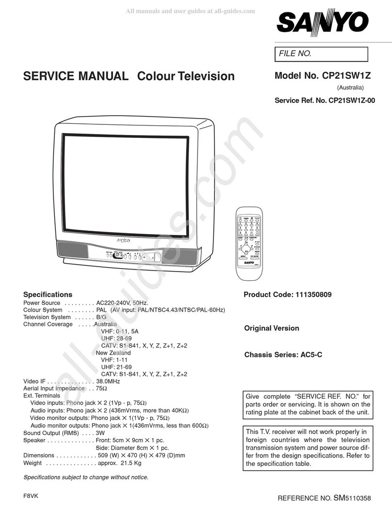
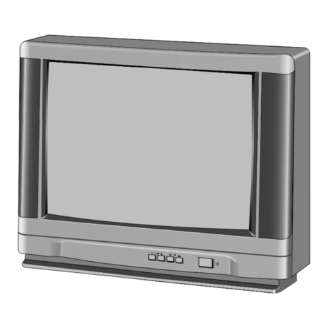
Sanyo CP29ST2 User manual

IFILE NO. I
SERVICE MANUAL Colour Television
Specifications
Power Source ........
Co[our System .......
Television System .....
—. Channel Coverage . . . .
VideolF ............
SoundlF ...........
Aerial Input Impedance
Ext. Terminals
.AC220-240V, 50 Hz.
.PAL (NTSC4.43, NTSC in AV mode)
.B/G
.VHF: O-11, 5A (Australia), 1-11 (New Zealand)
UHF:28-59 (Australia), 21-69 (New Zealand)
CATV S1-S41, X, Y, Z, Z+l, Z+2
.38.9MHz
.33.4 MHZ
.75Q
Video inputs: Phono jack x2(1 Vp -p, 75Q)
Audio inputs: Phono jack (R/L) x2(436mVrms, more than 40KQ)
Video monitor outputs: Phono jack x1(1Vp -p, 75$2)
Audio monitor outputs: Phono jack(R/L) x 1(436mVrms, less than 600Q)
Sound Output(RMS) ...Front speakers: 7.5W +7.5W
(CP29ST2CP29ST2T)
Dimensions ..........763(W) x590(H) x498(D)mm
Weight ..............approx.36 Kg
(CP25ST2)
Dimensions ..........691 (W) x528(H) x448(D)mm
Weight ..............approx.27.6 Kg
Specifications subject to change without notice.
F2DZIF2DYIF2EY
Model No. CP29ST2
CP29ST2T
CP25ST2
Australia, New Zealand
Service Ref. No. CP29ST2-UO
CP29ST2T~
CP25ST240
Product Code: 111338819 (CP29ST2)
111338818 (CP29ST2T)
111338718 (CP25ST2)
Original Version
Chassis Series: AC2-A
~
Give complete “SERVICE REF. NO.” for parts
order or servicing. It is shown on the rating plate
This T.V. receiver will not work properly in
foreign countries where the television
transmission system and power source dif-
fer from the design specifications. Refer to
the specification table.
REFERENCE NO. SM520264

Contents
Safety Notice ................................................’........................2
Chassis Block Diagram ..............................................................3-4
lC Block Diagrams ..................................................................5-7
Protection Circuit .....................................................................8
Service Adjustments Location.. .........................................................9
Service Adjustments with replacing Memory lC(lC802) ....................................10-12
Service Mode Adjustments ..........................................................13-14
Special Functions .................................................................15-18
Purity and Convergence Adjustment .....................................................19
Cabinet Parts List ...................................................................20
Chassis Electrical Parts List.... .........................................(CP29ST2-00) 21-30
(CP29ST2T-00) 31-41
(CP25ST2-00) 41-50
Safety Notice
SAFETY PRECAUTIONS
l: An isolation transformer should reconnected inthe 3: When replacing achassis in thecabinet, alwaysbe
power line between the receiver and the AC line certain that all the protective devices are installed
when aservice is performed on the primary of the properly, such as, control knobs, adjustment covers
converter transformer ofthe set. or shields, barriers, isolation resistor-capacitor net-
works etc.. Before returning any television to the
2: Comply with all caution and safety-related notes pro- customer, the service technician must be sure that
videdon the cabinet back, inside the cabinet, on the it is completely safe to operate without danger of
chassis orthe picture tube. electrical shock.
X-RADIATION PRECAUTION
The primary source of X-RADIATION in television receiver is the picture tube. The picture tube is specially con-
structedtoiimit X-RADIATION emissions. For continued X-RADIATION protection, the replacement tube mustbe
thesametypeas the original including suffix letter. Excessive high voltage may produce potentially hazardous
-RADIATION.TO avoid such hazards, the high voltage must be maintained within specified iimit. Refer tothisser-
vice manual, high voltage adjustment for specific high voltage limit. lf high voltage exceeds specified limits, take
necessary corrective action.Carefully follow the instructions for+Bl voltpowersupply adjustment, and high volt-
age checkto maintain the high voltage within the specified limits.
PRODUCT SAFETY NOTICE
Product safety should be considered when acomponent replacement is made in any area of areceiver.
Components indicated by mark ~in the parts list and the schematic diagram designate components in which
safety can be of special significance. It is particularly recommended that only parts designated on the parts list
in this manual be used for component replacement designated by mark ~.No deviations from resistance
wattage or voltage ratings may be made for replacement items designated by mark ~.
-
-2-
Chassis Block Diagrams
Following diagrams show the fundamental block diagrams for AC2 chassis and therefore differ slightly from actu-
al diagram of each TV set.
MAIN SIGNAL PROCESSING CIRCUIT
L==tt+l
11, .I I I
rl
I
,------
4
5
E
,,,,,,
$
Cu;
-t
A
4‘----h-l’ -------
c1
*_ EJ iiui
.q
%
a
I1
.. #.......
-3-

SYSTEM CONTROL
—
a
m
—
5
m
m
—
o
Em
s
(n
w
s’ Ocnmhc)mxt c90Jl- Oa)cobalnvm CN
=i-tmmmmmm mc9mc9NfNmJN Nmlcdml
7.
*lo CD r- Co 0(0 co 0
N
—
m
c1
z
<
mT
a0
z
z0
II
Q
w
J
-4-

IC Block Diagrams
QXXAVB241 <lF/Video/Chroma/Def. >
EXITAUDI(
IN
GND .
VIF
SIF
Vcc
Vcc
L
Ihkl
. .
42
.kW%cl+Lul 1-
IA
IIlmllll.ll e-1 uI~
HOUTPUT
MUTE
— OUT
—
—
— B-YIN
— R-YIN
_ DEFLECTION
GND
—:WJOMA
— y$o
—
—EXTIN
—WIN
.,, ,,.
IFAGCOUT AFT
-5-

LA7841 <Vertical Output >
LA4270 eSound Output >
II \
STR81 145A <Double Rectifier>
—
—
~1w
rl Z2
ZI
QI Q3* ‘
iSTR81145P
qin ygon
2Tl-
3T2
4Gate
5Common
—
-6-

MM1 369< 3D Surround Processor >
L
Vcc Lin Gll G12 G13 G14 FC Qf1Qf2 Qf3 Qf4 Lout
24 123 I22 121 I20 119 118 117 116 115 114 113
]1 12 13 14 15 16 ]7 18 19 110 ]11 412
Rin Grl Gr2 Gr3 Gr4 M/g Ref SPC Qi S/Q Rout Gnd
TDA8424 cSound Controller>
bass Lbass Rtreble Ltreble R
fihflh++
L-IN -
R-IN
II Vcap SDA SCL D.GND
Vcc GND
+L-OUT
+R-OUT
-7-

Protection Circuit
This TV set has abuilt-in power supply protection circuit.
It is provided to protect the TV set in case of apower supply circuit malfunctions. When something abnormality
occurs during TV reception, the TV set goes to the stand-by mode.
When an abnormality occurs during TV reception, it causes pin 24 of the CPU to go continually Low(less than
0.75V) for about one second. The CPU detects that this has occurred and outputs the signal from pin 15 to
switch off the power supply lines.
HReleasing the protective circuit and restoring power supply
To release the protective circuit and restore power supply, turn the power to the TV set OFF and then ON again
via either the main power switch or the ON-OFF button on the remote control. This will work only if the power
supply trouble was temporary. If there is permanent trouble such as adamaged circuit, power cannot be
restored and the circuit will have to be repaired.
-8-

Service Adjustments Location
_---- n~
“83’@,o’:Mg8kc~w
KCD
“837Q8313 c351cbuo 0
00(-)c355-_j 4
-JX161
)C138 ~
;~c~n g
F
Q137 ~
Q102
140 KK
Ql”l
0JW9
LI02
❑°
I\FOCUSADJ. \+BPOWERSUPPLYCHECK
SCREENVR
HORIZONTALWIDTHADJ.
-9-

Service Adjustments with Replacing Memory IC(IC802)
Note: The CPU (IC801 )and memory IC (IC802) store the service adjustments data and controls data for each circuit.
When the Memory IC(IC802) is replaced, some of the service adjustments should be readjusted to obtain the
best performance. The necessary service adjustments are carried out by using the RC handset. Please set
up the TV set with following steps [1] to [3].
[1] Initializing Procedure
1.Put anew memory IC.
2. Turn on the TV set.
3. Press and hold the ~V/AV] button on the TV set more than 2seconds. The following picture appears on the screen.
CLR
AV
4. Press the [FUNCTION] button on the TV set while the above On-Screen Display is still on the screen. The following
picture appears on the screen.
G
This completes the initialization of memory IC.
Following shows the initialized contents of memory data by this procedure.
-Plug &play :No executed - -
-Inhibit data :Cancelled
-Ch skip data :Cancelled
-Set volume control value to 10/63 steps.
-Set all of control values in PERSONAL mode to initial value shown in below table.
Note: When the memory IC replaced, the CPU writes the controls initial value to the replaced
memory IC as shown in below table.
Controls PERSONAL DYNAMIC NATURAL SOFT GAME
COLOUR 31/63 35/63 31/63 31/63 23/63
BRIGHT 31/63 33/63 31/63 34/63 26/63
CONTRAST 55/63 63/63 55/63 26/63 20/63
TINT 31/63 31/63 31/63 31/63 31/63
SHARPNESS 31/63 48/63 31/63 24/63 10/63
BASS*1 7/1 47/1 47/1 47/1 47/1 4
TREBLE*1 7/1 47114 7/1 47/1 47/1 4
BALANCE*1 7/1 47/1 47/1 47/1 47/1 4
Note: ●1Only available for Stereo decoder equipped model
d
-
-1o-

—
—
[2] Required Service Adjustments
Readjust the following service adjustments.
Adiustmenta Service Mode No. &Item
Horizontal centre adjustment Item 01, H-P
Vertical centre adjustment Item 02, V-P
Vertical size adjustment Item 03, V-S
OSD position adjustment Item 04, OSD
RF AGC adjustment Item 05, AGC
AFT adjustment Item 06, VCO
SIF adjustment Item 07, SIF
Grey scale adjustment Item 23-24, DRV
Further adjustment please refer to “Service adjustment-1” on page 13.
Following table shows the initial values which have been stored in the CPU ROM, and items for the service adjust-
ments.
Service mode adjustments table in CPU ROM
No. Item Initial value Range Description
01 H-P 80-15 Horizontal centre adjustment
02 v-P 40-7 Vertical centre adjustment
03 v-s 80 0-127 Vertical size adjustment
04 OSD 10-15 OSD position adjustment
05 AGC 64 0-127 RF AGC adjustment
06 Vco 128 0-255 VCO (AFT) adjustment
07 SIF o0-3 SIF VCO adjustment
08 SELF o0-15 SELF-adjusting
09 DLT 20-3 DL-time adjustment
10 DLF o0, 1DL-fine adjustment
11 B-ST o0, 1Black stretch on/off setting
12 ABCL 10, 1ABCL adjustment
13 AB-G o0, 1ABCL gain adjustment
14 TRAP 30-3 Trap frequency adjustment
15 WBK o0, 1White back setting
16 BBK o0, 1Blue back setting
17 AFCG 20-2 AFC gain adjustment
18 RBl o0-255 Red bias adjustment
19 GBI o0-255 Green bias adjustment
20 BBI o0-255 Blue bias adjustment
21 RD 64 0-127 Red drive adjustment
22 BD 64 0-127 Blue drive adjustment
23 DRV -- .. White balance adjustment *Grey scale adjustment
24 -- -- .. Y-cut setting
Notes:
+The initial value that the CPU writes down the CPU ROM data to the memory when replaced the memory IC. TV set
may not operate correctly with this initial value. It is required to set up the fine adjustment for service adjustments
described in the above.
-11-

[Entering to Service Mode]
1.Press and hold the [FUNCTION] button on the TV set and press the [1] button on the remote control handset,
Following setting setting items appears on the screen.
Display for [AGC] AGC adjustment
/
0010010
~Read Status
,tegy5-
Item Data value
Display for [DRV] White balance adjustment
~ReadStatus
0010010
23 DRV R64 B64.
/1\Data value for Blue
Item No. Ite’m Data value for Red
2. Select item by pressing the [OFF TIMER] or [MUTE] button on the remote control handset.
3. Adjust value by pressing the [VOLUME +] or [VOLUME -]button on the remote control handset.
To return to normal TV mode, press the [FUNCTION] button on the TV set or on the remote control handset.
[3] Special Function Setting
1.Following items should be set up in the special function mode, please refer to “Special Functions” on page 15 for
actual setting up.
-Volume Lock :OFF
-Tuning Lock :OFF
-AV Start :OFF
-Blue Back :OFF
-Music Mode :OFF
2. Confirm following system setting by pressing [RECALL] button on the remote control handset.
-Colour system :AUTO
-SIF system :s-1
*Note: There may be not available the above function depending on the specification of TV set.
-12-

Service Mode Adjustments
ADJUSTMENT-1
Following adjustments should be carried out when the memory IC is replaced. How to enter the service mode and
adjust values, please refer to” Entering to Service mode” on page 12.
(1) Receive the monochrome circular pattern.
(2) Set the brightness and contrast to normal.
(3) Select [H-P] in the service mode.
(4) Change value to be optimum horizontal centre position.
(5) Exit from the service mode.
‘Q Horizontal centre
.0
(1) Receive the monochrome circular pattern.
(2) Set the brightness and contrast to normal.
(3) Select [V-P] in the service mode.
(4) Change value to be optimum vertical centre position.
(5) Exit from the service mode.
Vertical centre
(1) Receive the monochrome circular pattern.
(2) Set the brightness and contrast to normal.
(3) Select [V-S] in the service mode.
(4) Change value to be optimum vertical size.
(5) Exit from the service mode.
Vertical size
NOTE: Do not attempt this adjustment with weak signal.
(1) Tune the receiver to most clearest (or strongest) VHF
station in your area. Set the brightness and contrast
controls to maximum. Set the colour control to mini-
mum.
(2) Select [AGC] in the service mode.
(3) Change value until the snow noise just disappears.
(4) Exit from the service mode.
(1) Input the SG signal to collector of Q101.
SG signal frequency :38.9MHz
SG signal level :70 dB
(2) connect ashort clip between the baseofQ101 and
ground.
(3) Connect oscilloscope to pin 2of IC201.
(4) Select [VCO] in the service mode.
(5) Change value until the voltage to be 4.5 *1.OV.
(6) Exit from the service mode.
(1) Tune the receiver to the clearest station with System
B/G(5.5MHz) in your area.
(2) Connect DC voltmeter to pin 46 of IC201 and ground.
(2) Select [SIF] in the service mode.
(3) Change value until the voltage to be about 3.0 V.
(4) Exit from the service mode.
(1) Receive the monochrome circular pattern.
(2) Set the brightness and contrast to normal.
(3) Select [OSD] in the service mode.
(4) Change value to be proper OSD position.
(5) Exit from the service mode.
.
-13-

(1) Receive the monochrome circular pattern.
(2) Set the brightness and colour to normal, contrast to
maximum.
(3) Enter to the service mode.
(4) Set each value of [RBI], [GBI], [BBI] mode to O.Set each
value of [RD], [BD] mode to 64.
(5) Select next of [DRV] mode to be one horizontal scan-
ning line and turn the screen volume on the FBT to
obtain just visible one coloured line.
(6) Press the [1], [2], [5], [6], [9] or [0] button to adjust the
brightness of each coiour until adim white line pro-
duced. Please see the control button allocations in this
mode.
(7) Select [DRVl mode to enter the white balance adjusting
mode.
(8) Press the [3], [4], [-/--] or [RECALL] button alternate-
ly to produce normal black and white picture.
(9) Exit from the service mode.
(10) Check for proper grey scale tracking at all brightness
levels.
NOTE: If the grey scale adjustment is made after picture
tube replacement, check the high voltage.
Red Bias ~
Red Bias -_
Green Bias +-
Green Bias --
Blue Bias A
Blue Bias --
LIRROUND BASS VAOB
000
Nton to
exit from service mode
/$H
Red Drive +
s
D-60 r“Red Drive -
G;: ,-Blue Drive+
m-1-- -Blue Drive -
66—0u
A/=T’’F%-P=l*I
—
ADJUSTMENT-2
Following adjustments are not required to readjust when replacing the memory lC.
(1) Connect DC meter to TP-B and the ground. (1) Receive the monochrome circular pattern.
(2) Set the brightness and contrast to normal. (2) Set the brightness and contrast to normal.
Tune the receiver to an active channel and synchro- (3) Adjust VR462 for optimum horizontal width.
nized picture.
(3) The B-voltage must be 140* 1volt DC.
(1) Receive the monochrome circular pattern.
(2) Set the brightness and contrast to maximum.
(3) Connect ahigh voltage probe to anode lead of the pic-
ture tube.
(4) The high voltage must be 29KV *1KV and less than
32KV at Obeam current.
NOTE:
If the picture tube is replaced, check the high voltage.
The horiz. width adjustment affects the high voltage.
Therefore, re-check the high voltage.
-14-

Special Functions
The following special functions can be set up on this TV set.
(1)VOLUME LOCK SETTING
(2) TUNING LOCK SETTING
(3) AV START SETTING
(4) BLUE BACK SEITING
(5) MUSIC MODE SEITING
IVolume Lock setting I
With this function, amaximum volume limit can be set at any level.
1Press the LEVEL button to set the desired maximum volume.
LEVEL (-)
-+
-
,$6#LEvEL(+)
ASOUND
11111111--------
~To enter Special Function setting mode, press and hold the FUNCTION button on the TV set, then press the
<remote control RECALIJCOLOUR SYSTEM button .
TV/AV PT ] F
&
@@
IFUNCTION
VOLUME LOCK OFF
a
@@’@8
@CD “’--
AA YSTEM RECALIJ
COLOUR SYSTEM
3Set VOLUME LOCK to the” ON” position by pressing the LEVEL (+ or - ) button. To cancel, set to the” OFF”
position.
b(d’f
OA= LEVEL
o
F4+
ODE SWAP
o
(+)
VOLUME LOCK ON &
LEVEL ( - )
~Press the RECALUCOLOUR SYSTEM button to return to the normal TV mode.
/
-15-

Once TUNING LOCK is switched on, further channel tuning (Pre-set) is not possible.
●To enter Special Function setting mode, press and hold the FUNCTION button on the TV set, then press the remote
~control RECALL/COLOUR SYSTEM button .
2
TWAV PT F
*
@@
IFUNCTION
‘RECALIJ
COLOUR SYSTEM
VOLUME LOCK OFF
Select” TUNING LOCK” by pressing the FUNCTION button on the remote control or the TV set.
It
FUNCTION
TUNING LOCK OFF
3Set TUNING LOCK to the “ON “position by pressing the LEVEL (+ or -)button. To cancel, set to the” OFF “
position.
LEVEL ( - ) k
CNSCAN
o-4
ODE o
<
FA+
SWAP
ot’
LEVEL (+)
TUNING LOCK ON
/
--
APressthe RECALIJCOLOURSYSTEMbutton to return to the normal TV mode.
-16-

Set AV-START to ON and every time the TV set is switched on, AV1
will be the initial programme position.
1
2
3
L
4
AV1
II
To enter Special Function setting mode, press and hold the FUNCTION button on the TV set. then press the
remote control RECALIJCOLOUR SYSTEM button .
Select” AV START” by pressing the FUNCTION button on the remote control or the TV set.
IP*FuNCTlON
Set AV START to the” ON” position by pressing the LEVEL (+ or - )
tion.
Av STARTOFF
button. To cancel, set to the” OFF” posi-
LEVEL(-,PEHLEVEL(+,
‘vsTARTONi
Press the RECALIJCOLOUR SYSTEM button to return to the normal TV mode,
Blue Back setting )
When BLUE BACK is on, ablue background will appear, if aI
programme position that is not receiving asignal is selected.
l-TVmode~
1To enter Special Function setting mode, press and hold the FUNCTION button on the TV set,
remote control RECALL/COLOUR SYSTEM button .
Turns blue when no
signal is received.
then press the
L2Select” BLUE BACK “by pressing the FUNCTION button on the remote control or the TV set.
1P*FUNCTION F
~Set BLUE BACK to the” ON “position by pressing the LEVEL (+ or - ) button. To cancel, set to the” OFF” posi-
~tion.
‘EvEL(-)&wLEvE
‘LUEBACK
ON x’
4Press the RECALUCOLOUR SYSTEM button to return to the normal TV mode.
L
-17-

IMusic Mode setting I
When Music Mode is ON, Programme position from “91” to “99 and “O”
are set Music Mode. Only sound is provided and any picture is not on
the screen under Music Mode.
MUSIC
A
99
.—
/Turns black
To enter Special Function setting mode, press and hold the FUNCTION button on the TV set. then press the
[remote control RECALUCOLOUR SYSTEM button .
NIAV PT F
FUNCTION
‘RECALIJ
COLOUR SYSTEM
VOLUME LOCK OFF
Select” MUSIC MODE” by pressing the FUNCTION button on the remote control or the TV set.
I‘_FLJNCTION MUSIC MODE OFF
QSet MUSIC MODE to the” ON “position by pressing the LEVEL (+ or -)button. To cancel, set to the” OFF”
-position.
LEVEL ( - )
F
-A
ODE
I!A-J”
o
<
F4+
SWAP
o
4Press the
T’
LEVEL (+)
/
MUSIC MODE ON
RECALUCOLOUR SYSTEM button to return to the normal TV mode.
-18-

Purity and Convergence Adjustment
.
CAUTION: The Convergence and Purity adjustments have been made at the factory. Readjustment
should be made only after picture tube or deflection yoke replacement, following the steps below:
PURITY ADJUSTMENT
1. Demagnetize the picture tube and receiver using an
external degaussing coil. When replacing picture tube or
deflection yoke, mount deflection yoke and purity-con-
vergence magnets assembly properly, see figures 1 and
4.
2. Turn Red and Blue guns off and provide only Green
raster. Rotate Screen control to fully counterclockwise.
Rotate Red and Blue Bias controls fully counterclock-
wise. Slowly rotate Green Bias control clockwise to pro-
duce Green raster.
3. Loosen the screw holding the Deflection Yoke and
remove the 3Rubber Wedges, and slide the Deflection
Yoke fully forward.
4. Rotate and spread the Tabs of the two Purity Magnets
to centre the vertical green belt in the picture screen.
The Purity Magnets are also adjusted to obtain vertical
centring of the raster.
5. Slowly slide the Deflection Yoke backward until auni-
form green screen is obtained.
6. Check the purity of the red and blue screens for unifor-
mity, turn off other colours to check this (use bias con-
trols). Readjust the yoke position if necessary until all
screens are pure.
7. Adjust each Bias control and screen control to obtain
white raster. Refer to Gray Scale Adjustment. If part of
the picture screen is coloured, adjust the Deflection
Yoke position forward or backward slightly.
FOUR- POLE
MAGNET TASS
Figure-1.PURITYAND CONVERGENCE MAGNETS
8. Tighten the mounting screw of the Deflection Yoke.
Adjust Convergence next.
CENTRE CONVERGENCE ADJUSTMENT
1.
2.
3.
4.
Use adot crosshatch pattern signal.
Turn Red and Blue guns on and turn off Green gun.
Adjust the angle between the Tabs of the Four Pole
Magnet 1 and 2, and superimpose the Red and Blue
vertical lines in the centre area of the picture screen.
Refer to figure 2.
Keeping the mutual angle of the Tabs of the Four Pole
Magnet turn them together to superimpose the Blue and
Red horizontal lines in the centre area of the picture
screen. Refer to figure 2.
Turn Green gun on and adjust Six Pole Magnet 3 and 4
that the Gre& line superimposed on the Red/Blue lines.
This is the same procedure used in steps 2 and 3.
Refer to figure 3.
OUTER AREA CONVERGENCE ADJUSTMENT
Slightly loosen the screw holding the Deflection Yoke.
Adjust the Deflection Yoke to converge the detail in the
outer area (left side and right side) of the picture screen by
orbital movement of the front of the Yoke, then secure the
Deflection Yoke in appropriate position by putting the
wedges as illustrated. Tighten screw holding the Deflection
Yoke.
DEFLECTION YOKE
IONYOKE
G SCREW
Fqure-4.ADJUSTMENT DEFLECTION YOKE
Adjust tabs angle to superimpose Adjust tabs angle to superimpose
blue and red vertical line. red/blue and green vertical line.
:*3’:’’” :*-p”
Figure- 2BLUE AND RED LINE MOVEMENT IFigure- 3BLUE/RED AND GREEN MOVEMENT
-19-

Cabinet Parts List F2Dz7F2DY/F2EY
Note: Parts order mustcontain Service Ref. No., Parf No., and descriptions.
1
42 5 I610 9 9
8712
11
\For 29”
13
Key No. Key No. Part No. Description
1610 274 2480 COMPL,CABINETFR-F2DA 9 610275 2335 BUTTONPW-F2EA
(CP29ST2-OO/CP29ST2T-OO) 10 610229 8406 SPRING-E3HA
610 274 2473 COMPL,CABINETFR-F2EA 11 610274 6884 CABINETBACK-F2DY
(CP25ST2-00) (cP29sT2-OO/CP29ST2T-OO)
l-a 610 273 2399 CABINETFRONT-F2DA 610 275 2366 CABINETBACK-F2EY
(CP29ST2-OO/CP29ST2T-OO) (cP25ST2-00)
610274 3883 CABINETFRONT-F2EA 610 102 7823 AC CORD HOLDER-D4VA
(cP25sT2-00) 610 273 5017 HOLDER SOUND PWB A-F2EA
l-b 645 027 7115 HANDLE,33X75,HQS 610 273 5024 HOLDER SOUND PWB B-F2EA
2 645 030 7355 BADGE, SANYO*53.5X12L53. 5 12 645 030 7492 ASSY,REMOCON JXMEB
3 610 273 4430 GRILLE SP R-F2DA (cP29ST2-OO/CP25ST2-OO)
(CP29ST2-00/CP29ST2T-00) 645 030 7485 ASSY,REMOCON JXMEA
610 273 3983 GRILLE SP R-F2F.A (CP29ST2T-00)
(CP25ST2-00) 12-a 610 261 8020 RC-BATTERY LID-JXZA
4 610 273 4447 GRILLE SP L-F2DA 610 274 3739 INSTRUCTIONS MANUAL-F2DY
(cP29sT2-OO/CP29ST2T-OO) 13 610 274 2329 LABEL RATING F2DZ
610 273 3990 GRILLE SP L-F2EA (CP29ST2-00)
(CP25ST2-00) 610 274 2312 LABEL RATING F2DY
5 610 273 4799 DOOR-F2EA (cP29ST2T-00)
6 610 273 4812 DEC IND-F2EA 610 274 2381 LABEL RATING F2EY
7610 273 9275 DEC CONTROL SHEET-F2EA (CP25ST2-00)
8610 104 2505 LATCH PUSH,7.9X6.9BK
645 019 2449 LATCH PuSH,7.9X6.9BK
-20-
Other manuals for CP29ST2
1
This manual suits for next models
2
Table of contents
Other Sanyo TV manuals

Sanyo
Sanyo LCD-39XR12F User manual

Sanyo
Sanyo CZP2510 User manual

Sanyo
Sanyo CPP3011V User manual

Sanyo
Sanyo CE15LC4-B User manual

Sanyo
Sanyo DS32224 User manual

Sanyo
Sanyo CR14SR8 User manual

Sanyo
Sanyo CE 25MT2A-C User manual

Sanyo
Sanyo CA21XS2 User manual

Sanyo
Sanyo 28dn2 User manual

Sanyo
Sanyo LCD-42XF4 User manual

Sanyo
Sanyo DP26746 - 26" LCD TV Product information sheet

Sanyo
Sanyo C28W1 User manual

Sanyo
Sanyo C20PE70 User manual

Sanyo
Sanyo DS19500 User manual

Sanyo
Sanyo CE28WN4J-B User manual

Sanyo
Sanyo HT30746 User manual

Sanyo
Sanyo DS25520 User manual

Sanyo
Sanyo CP28WF1 User manual

Sanyo
Sanyo CE21DN5-C User manual

Sanyo
Sanyo CA29YS2S User manual