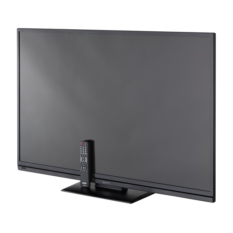
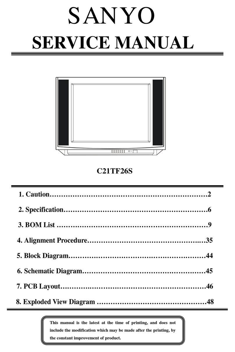
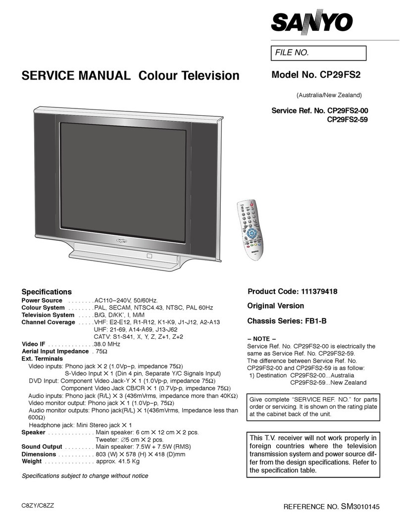
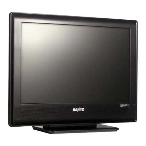
Sanyo DP42142 User manual

This guide is divided into 4 sections/pages depending on type of defect:
page 1)No Green LED Power Light.(LED never turns“ON”)
page 2)Green LED Light is “ON”, but Backlight is not “ON”,or only turn“ON & then OFF”.
page 3)Green LED Light is “ON”, and Backlight is “ON”, but there is no video/OSD.
page 4)Green LED Light turns “ON”, but then turns “OFF”within 10 seconds.
Please select the section/page that matches your defect and follow the flow chart.
These models & chassis versions are in this guide:
P42142-00
PLEASE KEEP THIS GUIDE.
IT WILL NOT BE PROVIDED FOR EVERY REPAIR.
P42142M-00
P42142-02
P42142M-02
SANYO
TROUBLESHOOTING GUIDE
2012 MODELS
P42142-00 / P42142M-00 / P42142-02 / P42142M-02
2012/03/23
2012-4A

Repair Flow Chart:Trouble Condition
Green Power LED does not turn on. The TV is dead.
Green Power LED:
Does not turn ON.
The TV is dead.
For Main board:
Is the “5VSTB” working normally?
(see TABLE*1.0)
Unplug(K7B) connector on
Power board. On Power board:
Is the “5VSTB” working normally?
(see TABLE*2.0)
Power board can not work.
Replace “Power board”.
Replace “Main board”.
Main board can not work.
Replace “Main board”.
No:0v
No:0v
Yes:5v
Yes:5v
Main board can not work.
Page 1
(TABLE *1.0)Main board:5VSTB Test Points
42" Models 5VSTB on Main board Conrmation Voltage
P42142-00 Z5GH
P42142M-00 Z5GHM
P42142-02 Z5GK
P42142M-02 Z5GKM
Main K8B Pin3 5V
(TABLE *2.0) Power board:5VSTB Test Points
42" Models 5VSTB on Power board Conrmation Voltage
P42142-00 Z5GH
P42142M-00 Z5GHM
P42142-02 Z5GK
P42142M-02 Z5GKM
Power K7B Pin3 5V

Repair Flow Chart:Trouble Condition
Green Power is on, but LCD backlight is not on.
Backlight does not turn on, or only turns on and then off.
Power LED turns ON,
but LCD backlight is not ON
or only turns ON and then
OFF.
For Main board:
Is the “BL_SW” voltage (3.3V)
Supplied from “K8B Pin13”?
For Power board:
Is the 0V supplied from “K703 Pin13”
during LED on?
The Panel is broken.
Replace “Panel”.
Main board can not work.
Replace “Main board”.
For Power board:
Is the 24V in “K703 Pin 1/2/3/4/5”
Power board can not work.
Replace “Power board”.
No:0V
Yes:3.3V
Yes:0V
No:over 0.8V
No:0V
Yes:24V
For Power board:
Is the BL-SW voltage (3.3V) supplied
from “K703 Pin12”
Confirm wire harness connection
between Main board and Power board.
No
Yes:3.3V
For Power board:
Is the BL-ADJ wave (PWM)from
“K703 Pin11” normally?
Confirm wire harness connection
between Power board and Main board .
No
Yes
The Panel is broken.
Replace the “Panel”.
Page 2
(TABLE *1.0) Main board: BL-SW Test Points
42" Models BL-SW on Main board Conrmation Voltage
P42142-00 Z5GH
P42142M-00 Z5GHM
P42142-02 Z5GK
P42142M-02 Z5GKM
Main K8B Pin13 3.3V
(TABLE *2.0) Power board: BL-ERR Test Points
42" Models BL-ERR on Power board Conrmation Voltage
P42142-00 Z5GH
P42142M-00 Z5GHM
P42142-02 Z5GK
P42142M-02 Z5GKM
Power K703 Pin13 0V

(TABLE *3.0) Power board: 24V Test Points
42" Models 24V on Power board Conrmation Voltage
P42142-00 Z5GH
P42142M-00 Z5GHM
P42142-02 Z5GK
P42142M-02 Z5GKM
Power K703 Pin1/2/3/4/5 24V
(TABLE *4.0) Power board: BL-SW Test Points
42" Models BL-SW on Power board Conrmation Voltage
P42142-00 Z5GH
P42142M-00 Z5GHM
P42142-02 Z5GK
P42142M-02 Z5GKM
Power K703 Pin12 3.3V
(TABLE *5.0) Power board: BL-ADJ Test Points
42" Models BL-ADJ on Power board Conrmation Voltage
P42142-00 Z5GH
P42142M-00 Z5GHM
P42142-02 Z5GK
P42142M-02 Z5GKM
Power K703 Pin11 PWM Wave

Repair Flow Chart:Trouble Condition
Green Power LED and LCD backlight is ON, but no video or OSD.
LCD backlight is ON,
but TV has NO VIDEO or OSD.
For Main board:
Is the 12V supplied from “K8B Pin 6/7”?
Replace“Power board” and
“Wire harness”.
Is LVDS signal working?
(see TABLE*1.0)
Confirm LVDS cable connection
and then check video or OSD again.
T-Con Board or LCD panel can not work.
1st:Replace“T-Con Board&LVDS Cable”.
If T-Con board&LVDS cable has no
problem, then 2nd:Replace“LCD Panel”.
Main board can not work.
Replace “Main board”.
If LVDS signal output is OK, the Main board is
normally OK, but can not be sure. If
the T-Con Board & LVDS has no problem,
please try the Main Board before changing
the panel.
No:0V
No:0V or 1.1Vconstant
Yes
Yse:12V
Page 3
(TABLE*1.0)Main board:"LVDS Clock"Test Points
42" Models LVDS Clock on Main board
P42142-00 Z5GH
P42142M-00 Z5GHM
P42142-02 Z5GK
P42142M-02 Z5GKM
K5LV Pin10 clock+
K5LV Pin8 clock-
Note:The bandwidth of the oscilloscope and probe must be at least 100MHZ or higher to check if the clock pulse exists.

Repair Flow Chart:Trouble Condition
Power LED turns OFF within 10 seconds after the TV power turns on.
Power LED turns OFF within
10 seconds after TV power
turns on.
For Main board:
Is 3.3V supplied to“K8B Pin1”during
LED power on ?
Unplug cable from Main board
to T-Con board whether the
symptom
changed?
Main board can not work.
Replace “Main board”.
For Power board:
Are the 12V and 24V supplied from “K7B Pin6/7&9 ”
during LED power on?
Main board can not work.
Replace “Main board ”.
T-Con board can not work.
Main board may also can not work.
Replace “T-Con board&Main board”.
Power board can not work.
Replace “Power board.”
No:0V
Yes:3.3V
Yes
No
No:0V
Yes
Page 4
(TABLE *1.0) Main board: Power-on Test Points
42" Models Power-on on Main board Conrmation Voltage
P42142-00 Z5GH
P42142M-00 Z5GHM
P42142-02 Z5GK
P42142M-02 Z5GKM
Main K8B Pin1 3.3V
(TABLE *2.0) Power board: 12V Test Points
42" Models 12V on Power board Conrmation Voltage
P42142-00 Z5GH
P42142M-00 Z5GHM
P42142-02 Z5GK
P42142M-02 Z5GKM
Power K7B Pin6/7 12V
(TABLE *3.0) Power board: 24V Test Points
42" Models 24V on Power board Conrmation Voltage
P42142-00 Z5GH
P42142M-00 Z5GHM
P42142-02 Z5GK
P42142M-02 Z5GKM
Power K7B Pin9 24V

Specifications
POWER RATING . . . . . . . . . . . . . . . . . . . . . . . . . 120VAC
90 W (AVG.)
ANTENNA INPUT IMPEDANCE. . . . . . . . . . . . . . . . . 75Ω
UHF/VHF/CATV
DIGITAL
RECEIVING CHANNEL . . . . . . . . . . . . . . . . . 2 - 13 (VHF),
14 - 69 (UHF),
01, 14-94, 95-135 (CATV)
1-135 (DIGITAL)
REMOTE READY. . . . . . . . . 36 KEY REMOTE CONTROL
SOUND OUTPUT. . . . . . . . . . . . . . . . . . . . . . . 10.0 W/CH
INTERMEDIATE FREQUENCY
PICTURE IF CARRIER . . . . . . . . . . . . . . . . . . 45.75MHz
SOUND IF CARRIER . . . . . . . . . . . . . . . . . . . 41.25MHz
COLOR SUB CARRIER . . . . . . . . . . . . . . . . . 42.17MHz
CABINET DIMENSIONS
WIDTH . . . . . . . . . . . . . . . . . . . . . . . . . . . . . . . . 990mm
HEIGHT . . . . . . . . . . . . . . . . . . . . . . . . . . . . . . . 628mm
DEPTH INCLUDING BASE . . . . . . . . . . . . . . . . 196mm
REFERENCE No. SM780203
DP42142, Z5GH, PRODUCT CODE 113025407
SERVICE MANUAL Remote Control Digital
Color Television DP42142
(U.S.A.) (CANADA)
ORIGINAL VERSION
Chassis No. P42142-00
NOTE: Match the Chassis No. on
the unit’s back cover with
the Chassis No. in the
Service Manual.
If the Original Version
Service Manual Chassis
No. does not match the
unit’s, additional Service
Literature is required. You
must refer to “Notices” to
the Original Service
Manual prior to servicing
the unit.
Servicing should be performed by only trained and qualified service personnel.
Contents
SAFETY INSTRUCTIONS. . . . . . . . . . . . . . . . . . . . . . . . . 2
SERVICE ADJUSTMENTS . . . . . . . . . . . . . . . . . . . . . . . . 3
ON-SCREEN SERVICE MENU . . . . . . . . . . . . . . . . . . . . . 4
POWER FAILURE CIRCUIT . . . . . . . . . . . . . . . . . . . . . . . 5
MECHANICAL DISASSEMBLY . . . . . . . . . . . . . . . . . . . . 6
CHASSIS ELECTRICAL PARTS LIST . . . . . . . . . . . . . . . . 9
COMPONENT AND TEST POINT LOCATIONS . . . . . . 27
BLOCK DIAGRAM POWER LINES. . . . . . . . . . . . . . . . . 30
BLOCK DIAGRAM SIGNAL LINES . . . . . . . . . . . . . . . . 31
IC BLOCK DIAGRAMS . . . . . . . . . . . . . . . . . . . . . . . . . . 32
TROUBLESHOOTING FLOW CHARTS . . . . . . . . . . . . . 36
SCHEMATIC NOTES . . . . . . . . . . . . . . . . . . . . . . . . . . . 39
IC, DIODE, AND TRANSISTOR PIN LAYOUTS. . . . . . . 40
PC BOARD CONNECTIONS AND LOCATIONS . . . . . . 41
CAPACITOR AND RESISTOR CODE CHART . . . . . . . . 42
SCHEMATIC DIAGRAMS. . . . . . . . . . . . . . . . . . . . . . . . 43
© Sanyo Manufacturing Corporation 2012
FILE No.

– 2 –
SAFETY PRECAUTIONS
WARNING: The chassis of this receiver has a floating
ground with the potential of one half the AC line voltage in
respect to earth ground. Service should not be attempted by
anyone not familiar with the precautions necessary when
working on this type of equipment.
The following precautions must be observed:
1. An isolation transformer must be connected in the power
line between the receiver and the AC line before any ser-
vice is performed on the receiver.
2. Comply with all caution and safety-related notes provid-
ed inside the cabinet, on the chassis, and on the back.
3. When replacing a chassis in the cabinet, always be certain
that all the protective devices are installed properly, such
as control knobs, adjustment covers, shields and barriers.
4. Before replacing the back cover of the set, thoroughly
inspect the inside of the cabinet to see that no stray parts
or tools have been left inside.
Before returning any television to the customer, the
service technician must perform the following safety
checks to be sure that the unit is completely safe to
operate without danger of electrical shock.
ANTENNA COLD CHECK
Remove AC plug from the 120 VAC outlet and place a
jumper across the two blades. Connect one lead of an ohm-
meter to the jumpered AC plug, and touch the other lead to
each exposed antenna terminal (UHF and VHF antenna ter-
minals). The resistance must measure between 1M ohm and
5.2M ohm. Any resistance value below or above this range
indicates an abnormality which requires corrective action.
LEAKAGE CURRENT CHECK
Plug the AC line cord directly into a 120 VAC outlet. (Do not
use an isolation transformer for this check.) Use an AC volt-
meter, that has 5000 ohms per volt or more sensitivity.
Connect a 1500 ohm 10 watt resistor, paralleled by a 0.15 μF
150 VAC capacitor, between a known good earth ground
(water pipe, conduit, etc.) and all exposed metal parts of the
cabinet (antennas, handle bracket, metal cabinet, screw
heads, metal overlays, control shafts, etc.). Measure the AC
voltage across the 1500 ohm resistor. The AC voltage
should not exceed 750 mV. A reading exceeding 750 mV
indicates that a dangerous potential exists. The fault must
be located and corrected. Repeat the above test with the
receiver power plug reversed.
NEVER RETURN A RECEIVER TO THE CUSTOMER
WITHOUT TAKING THE NECESSARY CORRECTIVE ACTION.
PRODUCT SAFETY NOTICE
When replacing components in a receiver, always keep in
mind the necessary product safety precautions. Pay special
attention to the replacement of components marked with a
in the parts list and in the schematic diagrams. To ensure
safe product operation, it is necessary to replace those com-
ponents with the exact same PARTS.
SERVICING ELECTROSTATICALLY SENSITIVE DEVICES
Semiconductors (solid-state devices) that can be damaged
by static electricity are referred to as Electrostatically
Sensitive (ES) devices. Examples of typical ES devices are:
Integrated Circuits (IC), Field-Effect Transistors (FET), and
“chip” components. The following techniques should be
observed strictly, to reduce the occurrence of semiconduc-
tor damage due to electrostatic discharge.
1. Immediately prior to handling any semiconductor com-
ponent or an assembly containing a semiconductor
device or devices, discharge the electrostatic buildup on
your body by touching a known earth ground. You may
also obtain and wear a commercially available discharg-
ing wrist strap device.
CAUTION: Be sure to remove the wrist strap before
applying power to any unit being serviced.
2. After removing an ES equipped assembly, place it on a
conductive surface, such as, aluminum foil, to prevent
buildup or exposure to static electricity.
3. Use only grounded-tip soldering irons to solder or unsol-
der ES devices.
4. Use only anti-static solder removal devices. Some suc-
tion-type devices can generate static electricity adequate
to damage ES devices.
5. A replacement ES device will come packaged in protective
material (conductive foam, aluminum foil, or some compa-
rable conductive material). Do Not remove an ES device
from its protective packaging unless you are prepared to
install it immediately.
6. Precisely prior to removing an ES device from its protective
packaging, touch the protective packaging to the chassis or
assembly in which the device will be installed.
CAUTION: Be sure that no power is applied to the chassis
or circuit assembly.
7. Incidental body movements, such as, lifting a foot from
a carpeted floor or the rubbing of fabric together can
generate static electricity sufficient to damage ES devices.
Therefore, minimize all body movements while handling
exposed (unpackaged) ES devices.
SAFETY INSTRUCTIONS
– 3 –
GENERAL
This set has an On-screen Service Menu system included in
the CPU that allows remote operation for most of the
service adjustments.
ON-SCREEN SERVICE MENU SYSTEM
1. Enter the Service Menu:
•Turn off the receiver and disconnect the AC power
supply.
•While pressing the Volume (––) button on the televi-
sion, reconnect the AC power supply. The Service
Menu will now appear. The remote can now be used
to make adjustments. See Figure 1 below.
2. Service Adjustments:
•Press the Cursor and key to select the desired
service menu item you want to adjust. See page 4 for
the On-screen Service Menu.
•Use the Cursor or key to adjust the data.
The or key will increase or decrease the data
sequentially.
3. Exit from the Service Menu:
•Press the MENU key to turn off the Service Menu
display.
Figure 1. Service Menu Display
HEX DATA
Index ParameterName
FACTORY_VOL 0x21 48 0 255
Value Def. MIN MAX
1
ITEM NO. TITLE
POWER
INPUT
ENTER
MENU
VOL
CH
POWER
INPUT
ENTER
MENU
VOL
CH
Volume – :Enter Service Menu
SUB CH
INFO DYN VOL
Menu:
Exit Service Menu
Cursor :
Select Item
Cursor :
Adjust the data
SERVICE ADJUSTMENTS

– 4 –
Table 1. ON-SCREEN SERVICE MENU
When IC5750 (Flash Memory) is replaced, check the bus data to confirm they are the same as below. See page 3 for
On-Screen Service Menu access and adjustments.
PROGRAM CODES
The microprocessor used in this model is a multi-purpose type and is used in several different models. To ensure
proper operation and the correct features for your particular model, the program codes must be correct.
Note 1. Option Data 1 (Index 02) should be hexadecimal 00.
See Index 02 above. If this program code is wrong the TV will not operate properly.
Note 2. Option Data 2 (Index 03) should be hexadecimal 11.
See Index 03 above. If this program code is wrong the TV will not operate properly.
NOTES: Option 2 Data (Display Panel)
Option 1 and Option 2 data is initial and can be set according to adjusment information.
Index ParameterName Value Min Max
02 OP1 00h 0 255
03 OP2 11h 0 255
ON-SCREEN SERVICE MENU

– 5 –
Check the following if the unit is turned off by the power
failure detector.
1. Disconnect the AC power cord (120V AC line) for a short
time.
2. Connect a DC Voltmeter to the circuits shown below.
3. Press the Power key and check for the proper voltage
supplies.
4. If any of these voltages is low, the power failure detec-
tor should turn the unit off within three seconds.
5. Check all circuits shown below.
Note: If power failure is detected 3 times in 15 minutes,
the set will enter the standby mode and cannot be
switched On.To reset the operating programs of the
sub_CPU it is necessary to disconnect the AC cord
for a short time.
Internal sub_CPU on main IC 5500 is programmed so the
set will go to standby mode when there is circuit failure as
described below. (Refer to“Block Diagram Power Lines”.)
This unit is equipped with a Power Failure Detector function
included in the sub_CPU which checks for an abnormal
condition in the chassis power supplies.
If, while the power is on, a failure is caused by any of the fol-
lowing that results in a low voltage supply, the sub_CPU will
turn the unit off in 1.5 seconds to prevent further damage:
•Failure within the power supply circuits.
•A short circuit in the load side from the supply.
Power Failure: Detected voltage failure for circuit.
(Connected to IC5500 pin 234.)
(Normal: High; Failure: Low)
If, while the power is off, the power is switched on and any
of these failures remains uncorrected, the sub_CPU will
shut off the power within three seconds.
IC5500
Power Fail
Power On
Power Board
Main
D6700
D1668
5V STB
Audio Pow
D1613
5V
230 234
POWER FAILURE CIRCUIT

LVDS cable
– 6 –
BACK CABINET REMOVAL
1. Remove 19 screws (C:3x10, 15 pcs.; D:4x8, 4 pcs.)
2. Detach AC cord from cabinet back.
3. Take off the cabinet back.
The board installed in the panel and the speaker are
installed in front cabinet.
CAUTION:
This LCD TV uses several different kinds of screws. Using the correct screw is necessary to prevent damage.
Lead wires must be redressed to their previous locations after servicing. The Earth sheet and gasket are
provided to prevent interference to other radio and television receivers. The Earth sheet and gasket should
be returned to its previous position after servicing.
STAND REMOVAL
Position TV face down on a padded or cushioned
surface to protect the screen and finish.
Remove 4 screws (A:6X30, 2pcs; B:6x40, 2pcs)
and remove the stand legs from the TV.
POWER UNIT REMOVAL
Remove 4 screws (E:3x6) to take the power unit off.
MECHANICAL DISASSEMBLY

– 7 –
MAIN BOARD AND CHASSIS BASE REMOVAL
Remove 4 screws (E:3x6), and one (1) Nut (F) to take the
main board off.
SPEAKER REMOVAL
No screws.
Take off each speaker from Front Cabinet directly.
ATTENTION
– The terminal base and button united
should be returned to their previous
position after servicing.
MECHANICAL DISASSEMBLY (Continued)

– 8 –
ELECTROSTATICALLY SENSITIVE DEVICES
Many solid-state devices (especially Integrated Circuits) are Electrostatically Sensitive,
and, therefore, require special handling techniques as described under “Servicing
Electrostatically Sensitive Devices,” on page two in this service literature.
RC BOARD REMOVAL
Remove 1 screws (C:3x10) to take the RC BOARD off.
MOUNTING WALL REMOVAL
Remove 2 nuts (G) from the cabinet back
ATTENTION
– Confirm Mounting wall wire is installed when you install
the back cabinet.
– Need to use the hot-melt method to remove the mount-
ing wall, generally need not remove the mounting wall
through servicing.
MECHANICAL DISASSEMBLY (Continued)

– 9 –
CAUTION: To Protect against electrical shock and for continued product safety, refer to SAFETY PRECAUTIONS
and PRODUCT SAFETY NOTICE on Page 2
PRODUCT SAFETY NOTICE
PRODUCT SAFETY SHOULD BE CONSIDERED WHEN A REPLACEMENT IS MADE IN ANY AREA OF A RECEIVER.
COMPONENTS INDICATED BY A IN THIS PARTS LIST AND THE SCHEMATIC DIAGRAM DESIGNATE
COMPONENTS IN WHICH SAFETY CAN BE OF SPECIAL SIGNIFICANCE. IT IS PARTICULARLY RECOMMENDED
THAT ONLY PARTS DESIGNATED ON THE FOLLOWING PARTS LIST BE USED FOR COMPONENT REPLACE-
MENT DESIGNATED BY A . NO DEVIATIONS FROM RESISTANCE, WATTAGE, AND VOLTAGE RATINGS MAY
BE MADE FOR REPLACEMENT ITEMS DESIGNATED BY A .
Schematic
Location Part No. Description Schematic
Location Part No. Description
Note: Schematic part location numbers may not always match with the part descriptions.
The part descriptions are correct and should be used.
CAPACITORS RESISTORS
CHASSIS ELECTRICAL PARTS LIST
NOTES:
Read Description of the Capacitor as follows:
(Example)
CERAMIC 100P K 50V
Rated Voltage
Tolerance Symbols:
Less than 10pF
A : Not specified
D : ±0.5pF
G : ±2pF
R : ±0.25-0pF
B : ±0.1pF
E : +0-1pF
H : +0.1-0pF
S: ±0.25-0pF
C : ±0.25pF
F : ±1pF
L : +0-0.1pF
More than 10pF
A : Not specified
D : ±0.5%
H : ±3%
L : ±15%
P : +100-0%
U : +75-10%
X : +40-20%
B : ±0.1%
F : ±1%
J : ±5%
M : ±20%
Q : +30-10%
V : +20-10%
Y : +150-10%
C : ±0.25%
G : ±2%
K : ±10%
N : ±30%
T : +50-10%
W : +100-10%
Z : +80-20%
Rated value: P=pico tarad, U=micro tarad
Material:
CERAMIC . . . . . . .
MT-PAPER. . . . . . .
POLYESTER . . . . .
MT-POLYEST . . . .
POLYPRO . . . . . . .
MT-POLYPRO . . . .
COMPO FILM . . . .
MT-COMPO. . . . . .
STYRENE . . . . . . .
TA-SOLID . . . . . . .
AL-SOLID . . . . . . .
ELECT . . . . . . . . . .
NP-ELECT . . . . . . .
OS-SOLID . . . . . . .
Ceramic
Metallized Paper
Polyester
Metallized Polyester
Polypropylene
Metallized Polypropylene
Composite Film
Metallized Composite
Styrene
Tantalum Solid
Aluminum Solid
Electrolytic
Non-polarised Electrolytic
Alluminum Solid with Organic
Semiconductive Electrolytic
NOTES:
Read Description of the Resistor as follows:
(Example)
CARBON 4.7K J A 1/4W
Rated Wattage
A...0.05%
D...0.5%
J...5%
P...+5-15%
B...0.1%
F...1%
K...10%
C...25%
G...2%
M...20%
Rated value, ohms:
K...1,000 M...1,000,000
Material:
CARBON . . . . . . . .
MT-FILM . . . . . . . .
OXIDE-MT. . . . . . .
SOLID . . . . . . . . . .
MT-GLAZE . . . . . .
WIRE WOUND . . .
CERAMIC RES . . .
FUSIBLE RES . . . .
Carbon
Metal Film
Oxide Metal Film
Composition
Metal Glaze
Wire wound
Ceramic
Fusible
Performance Symbols:
A...General B..Non-flammable
Z...Low noise
Other...Temperature coefficient
Tolerance Symbols:

– 10 –
Schematic
Location Part No. Description Schematic
Location Part No. Description
CABINET PARTS
1JC0BUM0623— BUTTON UNITED-Z5SE
1JC0CAM0772-C CABINET FRONT-Z5GH
1JC0CBM0548A- CABINET BACK-Z5GH
ACCESSORY
1JC0P1P0015— DP42142 ENGLISH SHEET-Z5GH
1JC0P1P0016— DP42142 SPANISH SHEET-Z5GH
MAIN DIGITAL BOARD
CAPACITORS
C001 F1H1H102A219 CERAMIC 1000P K 50V
C002 F1H1H102A219 CERAMIC 1000P K 50V
C003 F1J1E105A213 CERAMIC 1U K 25V
C004 F1J1E105A213 CERAMIC 1U K 25V
C005 F1H1H102A219 CERAMIC 1000P K 50V
C006 F1H1H102A219 CERAMIC 1000P K 50V
C007 F1H1H102A219 CERAMIC 1000P K 50V
C008 F1H1H102A219 CERAMIC 1000P K 50V
C009 F1H1H104A913 CERAMIC 0.1U K 50V
C010 F1H1H104A913 CERAMIC 0.1U K 50V
C011 F1H1H104A913 CERAMIC 0.1U K 50V
C012 F1H1H104A913 CERAMIC 0.1U K 50V
C013 F1H1H104A913 CERAMIC 0.1U K 50V
C014 F1H1H104A913 CERAMIC 0.1U K 50V
C015 F1H1H104A913 CERAMIC 0.1U K 50V
C016 F1H1H104A913 CERAMIC 0.1U K 50V
C018 F1H1H331A792 CERAMIC 330P J 50V
C019 F1H1H331A792 CERAMIC 330P J 50V
C020 F1J1E105A213 CERAMIC 1U K 25V
C021 F1H1H104A913 CERAMIC 0.1U K 50V
C022 F1H1H104A913 CERAMIC 0.1U K 50V
C023 F1J1E105A213 CERAMIC 1U K 25V
C024 F1G1C104A077 CERAMIC 0.1U K 16V
C025 F1G1C104A077 CERAMIC 0.1U K 16V
C026 F1G1C104A077 CERAMIC 0.1U K 16V
C027 F1G1C104A077 CERAMIC 0.1U K 16V
C028 F1G1H150A541 CERAMIC 15P J 50V
C029 F1G1H150A541 CERAMIC 15P J 50V
C030 F1G1H221A737 CERAMIC 220P J 50V
C031 F1G1H681A571 CERAMIC 680P K 50V
C032 F1G1H101A541 CERAMIC 100P J 50V
C033 F1G1H472A571 CERAMIC 4700P K 50V
C034 F1G1C104A077 CERAMIC 0.1U K 16V
C035 F1G1C104A077 CERAMIC 0.1U K 16V
C036 F1J1E105A213 CERAMIC 1U K 25V
C037 F1J1E105A213 CERAMIC 1U K 25V
C038 F1G1C104A077 CERAMIC 0.1U K 16V
C040 F1G1C104A077 CERAMIC 0.1U K 16V
C041 F1G1C104A077 CERAMIC 0.1U K 16V
C042 F1G1C104A077 CERAMIC 0.1U K 16V
C1020 F1J0J106A004 CERAMIC 10U K 6.3V
F1J0J106A020 CERAMIC 10U K 6.3V
C1021 F1G1H390A541 CERAMIC 39P J 50V
C1600 F1J0J106A004 CERAMIC 10U K 6.3V
F1J0J106A020 CERAMIC 10U K 6.3V
C1602 F2G1C2210024 ELECT 220U M 16V
F2G1C221A066 ELECT 220U M 16V
C1603 F1H1H104A913 CERAMIC 0.1U K 50V
C1604 F2G1C2210024 ELECT 220U M 16V
F2G1C221A066 ELECT 220U M 16V
C1607 F2G1C2210024 ELECT 220U M 16V
F2G1C221A066 ELECT 220U M 16V
C1610 F1H1C473A041 CERAMIC 0.047U K 16V
C1612 F1H1H104A913 CERAMIC 0.1U K 50V
C1613 F1H1H104A913 CERAMIC 0.1U K 50V
C1614 F1G1A105A047 CERAMIC 1U K 10V
C1615 F1G1C104A077 CERAMIC 0.1U K 16V
C1616 F1H1H104A913 CERAMIC 0.1U K 50V
C1618 F1G1H472A571 CERAMIC 4700P K 50V
C1619 F2G1V1010030 ELECT 100U M 35V
F2G1V101A058 ELECT 100U M 35V
C1624 F1H1E105A100 CERAMIC 1U K 25V
C1626 F2G1E4710010 ELECT 470U M 25V
F2G1E471A185 ELECT 470U M 25V
C1704 F1H1H103A219 CERAMIC 0.01U K 50V
C1800 F1H1H104A913 CERAMIC 0.1U K 50V
C1801 F1J0J106A004 CERAMIC 10U K 6.3V
F1J0J106A020 CERAMIC 10U K 6.3V
C1803 F1H1H103A219 CERAMIC 0.01U K 50V
C2402 F1H1H104A913 CERAMIC 0.1U K 50V
C5505 F1J0J106A004 CERAMIC 10U K 6.3V
F1J0J106A020 CERAMIC 10U K 6.3V
C5506 F1G1H103A706 CERAMIC 0.01U K 50V
C5507 F1H0J4750004 CERAMIC 4.7U K 6.3V
C5508 F1G1C104A077 CERAMIC 0.1U K 16V
C5509 F1J0J106A004 CERAMIC 10U K 6.3V
F1J0J106A020 CERAMIC 10U K 6.3V
C5510 F1G1C104A077 CERAMIC 0.1U K 16V
C5511 F1G1H1020008 CERAMIC 1000P K 50V
C5512 F1G1C104A077 CERAMIC 0.1U K 16V
C5513 F1G1C104A077 CERAMIC 0.1U K 16V
C5514 F1G1H1020008 CERAMIC 1000P K 50V
C5515 F1G1H1020008 CERAMIC 1000P K 50V
C5516 F1G1H103A706 CERAMIC 0.01U K 50V
C5517 F1G1H221A737 CERAMIC 220P J 50V
C5518 F1G1C104A077 CERAMIC 0.1U K 16V
C5519 F1G1H103A706 CERAMIC 0.01U K 50V
C5520 F1G1C104A077 CERAMIC 0.1U K 16V
C5522 F1G1H390A541 CERAMIC 39P J 50V
C5523 F1J0J106A004 CERAMIC 10U K 6.3V
F1J0J106A020 CERAMIC 10U K 6.3V
C5525 F1G1H221A737 CERAMIC 220P J 50V
C5527 F1G1H103A706 CERAMIC 0.01U K 50V
C5528 F1G1C104A077 CERAMIC 0.1U K 16V
C5531 F1G1C104A077 CERAMIC 0.1U K 16V
C5532 F1J0J106A004 CERAMIC 10U K 6.3V
F1J0J106A020 CERAMIC 10U K 6.3V
C5533 F1G1C104A077 CERAMIC 0.1U K 16V
C5534 F1G1H103A706 CERAMIC 0.01U K 50V
C5535 F1G1H1020008 CERAMIC 1000P K 50V

– 11 –
Schematic
Location Part No. Description Schematic
Location Part No. Description
C5536 F1G1H221A737 CERAMIC 220P J 50V
C5537 F1J0J106A004 CERAMIC 10U K 6.3V
F1J0J106A020 CERAMIC 10U K 6.3V
C5538 F1G1H1020008 CERAMIC 1000P K 50V
C5539 F1G1H103A706 CERAMIC 0.01U K 50V
C5540 F1G1H1020008 CERAMIC 1000P K 50V
C5541 F1G1H103A706 CERAMIC 0.01U K 50V
C5542 F1J0J106A004 CERAMIC 10U K 6.3V
F1J0J106A020 CERAMIC 10U K 6.3V
C5543 F1G1H103A706 CERAMIC 0.01U K 50V
C5544 F1G1A105A047 CERAMIC 1U K 10V
C5546 F1G1C104A077 CERAMIC 0.1U K 16V
C5547 F1G1H392A571 CERAMIC 3900P K 50V
C5549 F1G1C104A077 CERAMIC 0.1U K 16V
C5550 F1G1H103A706 CERAMIC 0.01U K 50V
C5551 F1G1H1020008 CERAMIC 1000P K 50V
C5552 F1G1C104A077 CERAMIC 0.1U K 16V
C5553 F1G1H103A706 CERAMIC 0.01U K 50V
C5554 F1J0J106A004 CERAMIC 10U K 6.3V
F1J0J106A020 CERAMIC 10U K 6.3V
C5555 F1G1C104A077 CERAMIC 0.1U K 16V
C5556 F1J0J106A004 CERAMIC 10U K 6.3V
F1J0J106A020 CERAMIC 10U K 6.3V
C5557 F1G1A105A047 CERAMIC 1U K 10V
C5558 F1G1H1020008 CERAMIC 1000P K 50V
C5559 F1G1H1020008 CERAMIC 1000P K 50V
C5560 F1G1A105A047 CERAMIC 1U K 10V
C5561 F1G1H1020008 CERAMIC 1000P K 50V
C5562 F1G1C104A077 CERAMIC 0.1U K 16V
C5563 F1G1C104A077 CERAMIC 0.1U K 16V
C5565 F1J0J106A004 CERAMIC 10U K 6.3V
F1J0J106A020 CERAMIC 10U K 6.3V
C5566 F1G1A105A047 CERAMIC 1U K 10V
C5567 F1H0J4750004 CERAMIC 4.7U K 6.3V
C5568 F1G1H1020008 CERAMIC 1000P K 50V
C5569 F1G1C104A077 CERAMIC 0.1U K 16V
C5570 F1J0J106A004 CERAMIC 10U K 6.3V
F1J0J106A020 CERAMIC 10U K 6.3V
C5571 F1G1C104A077 CERAMIC 0.1U K 16V
C5572 F1G1A105A047 CERAMIC 1U K 10V
C5574 F1G1A105A047 CERAMIC 1U K 10V
C5576 F1G1A105A047 CERAMIC 1U K 10V
C5577 F1G1A105A047 CERAMIC 1U K 10V
C5578 F1G1A105A047 CERAMIC 1U K 10V
C5579 F1G1A105A047 CERAMIC 1U K 10V
C5590 F1G1E473A091 CERAMIC 0.047U K 25V
C5592 F1G1C104A077 CERAMIC 0.1U K 16V
C5595 F1G1E473A091 CERAMIC 0.047U K 25V
C5597 F1G1H103A706 CERAMIC 0.01U K 50V
C5600 F1G1E473A091 CERAMIC 0.047U K 25V
C5602 F1G1E473A091 CERAMIC 0.047U K 25V
C5605 F1G1H270A541 CERAMIC 27P J 50V
C5608 F1G1H270A541 CERAMIC 27P J 50V
C5613 F1H1H1500009 CERAMIC 15P J 50V
C5614 F1H1H1500009 CERAMIC 15P J 50V
C5615 F1G1C104A077 CERAMIC 0.1U K 16V
C5616 F1G1C104A077 CERAMIC 0.1U K 16V
C5617 D0GA103JA047 MT-GLAZE 10K JA 1/16W
C5618 F1G1C104A077 CERAMIC 0.1U K 16V
C5619 F1G1H150A541 CERAMIC 15P J 50V
C5620 D0GA103JA047 MT-GLAZE 10K JA 1/16W
C5653 F1G1C104A077 CERAMIC 0.1U K 16V
C5661 F1G1C104A077 CERAMIC 0.1U K 16V
C5700 F1G1A105A047 CERAMIC 1U K 10V
C5701 F1G1C104A077 CERAMIC 0.1U K 16V
C5702 F1G1A105A047 CERAMIC 1U K 10V
C5703 F1G1C104A077 CERAMIC 0.1U K 16V
C5704 F1G1C104A077 CERAMIC 0.1U K 16V
C5705 F1G1C104A077 CERAMIC 0.1U K 16V
C5707 F1G1C104A077 CERAMIC 0.1U K 16V
C5708 F1G1C104A077 CERAMIC 0.1U K 16V
C5709 F1G1C104A077 CERAMIC 0.1U K 16V
C5711 F1G1C104A077 CERAMIC 0.1U K 16V
C5712 F1G1C104A077 CERAMIC 0.1U K 16V
C5713 F1G1C104A077 CERAMIC 0.1U K 16V
C5714 F1J0J106A004 CERAMIC 10U K 6.3V
F1J0J106A020 CERAMIC 10U K 6.3V
C5715 F1J0J106A004 CERAMIC 10U K 6.3V
F1J0J106A020 CERAMIC 10U K 6.3V
C5750 F1G1A105A047 CERAMIC 1U K 10V
C5811 F1G1H100A541 CERAMIC 10P J 50V
C5902 F1G1C104A077 CERAMIC 0.1U K 16V
C5903 F1G1A684A047 CERAMIC 0.68U K 10V
C5905 F1G1C104A077 CERAMIC 0.1U K 16V
C6108 F1H1H680A831 CERAMIC 68P J 50V
C6113 F1H1H102A219 CERAMIC 1000P K 50V
C6114 F1H1H680A831 CERAMIC 68P J 50V
C6202 F1G1H2R0A713 CERAMIC 2P B 50V
C6206 F1G0J1050007 CERAMIC 1U K 6.3V
C6207 F1G0J1050007 CERAMIC 1U K 6.3V
C6214 F1G1C104A077 CERAMIC 0.1U K 16V
C6249 F1G1H472A571 CERAMIC 4700P K 50V
C6253 F1G1H472A571 CERAMIC 4700P K 50V
C6261 F1G1C104A077 CERAMIC 0.1U K 16V
C6262 F1G0J1050007 CERAMIC 1U K 6.3V
C6263 F1G0J1050007 CERAMIC 1U K 6.3V
C6268 F1G1C104A077 CERAMIC 0.1U K 16V
C6270 F1G1C104A077 CERAMIC 0.1U K 16V
C6272 F1G1H1020008 CERAMIC 1000P K 50V
C6274 F1G1H181A541 CERAMIC 180P J 50V
C6275 F1G1H101A541 CERAMIC 100P J 50V
C6276 F1G1H1020008 CERAMIC 1000P K 50V
C6277 F1G1H820A541 CERAMIC 82P J 50V
C6278 F1G1H1020008 CERAMIC 1000P K 50V
C6330 F1G1C104A077 CERAMIC 0.1U K 16V
C6332 F2G1C2210024 ELECT 220U M 16V
F2G1C221A066 ELECT 220U M 16V
C6500 F1G1C104A077 CERAMIC 0.1U K 16V
C6501 F1G1C104A077 CERAMIC 0.1U K 16V
C6530 F1G1C104A077 CERAMIC 0.1U K 16V
C6531 F1G1C104A077 CERAMIC 0.1U K 16V

– 12 –
Schematic
Location Part No. Description Schematic
Location Part No. Description
C6560 F1G1C104A077 CERAMIC 0.1U K 16V
C6561 F1G1C104A077 CERAMIC 0.1U K 16V
C6600 F1G1A105A047 CERAMIC 1U K 10V
C6601 F1G1A105A047 CERAMIC 1U K 10V
C6602 F2G1C2210024 ELECT 220U M 16V
F2G1C221A066 ELECT 220U M 16V
C6605 F2G1C2210024 ELECT 220U M 16V
F2G1C221A066 ELECT 220U M 16V
C6701 F1G1C104A077 CERAMIC 0.1U K 16V
C6702 F1G1C104A077 CERAMIC 0.1U K 16V
C6703 F1J0J106A004 CERAMIC 10U K 6.3V
F1J0J106A020 CERAMIC 10U K 6.3V
C6706 F1G1C104A077 CERAMIC 0.1U K 16V
C6707 F2G1C2210024 ELECT 220U M 16V
F2G1C221A066 ELECT 220U M 16V
C6708 F1G1A2240008 CERAMIC 0.22U K 10V
C6709 F2G1C2210024 ELECT 220U M 16V
F2G1C221A066 ELECT 220U M 16V
C6720 F1H0J4750004 CERAMIC 4.7U K 6.3V
C6721 F1G1C104A077 CERAMIC 0.1U K 16V
C6722 F1G1C104A077 CERAMIC 0.1U K 16V
C6723 F1G1A105A047 CERAMIC 1U K 10V
C6724 F1G1H392A571 CERAMIC 3900P K 50V
C6727 F2G1C4710029 ELECT 470U M 16V
F2G1C471A066 ELECT 470U M 16V
C6728 F1G1H103A706 CERAMIC 0.01U K 50V
C6729 F1G1C104A077 CERAMIC 0.1U K 16V
C6730 F1G1H221A737 CERAMIC 220P J 50V
C6733 F1G1A105A047 CERAMIC 1U K 10V
C6740 F1G1A2240008 CERAMIC 0.22U K 10V
C6741 F1G1C104A077 CERAMIC 0.1U K 16V
C6742 F1G1C104A077 CERAMIC 0.1U K 16V
C6743 F2G1C2210024 ELECT 220U M 16V
F2G1C221A066 ELECT 220U M 16V
C6752 F1G1E473A091 CERAMIC 0.047U K 25V
C6753 F1G1A105A047 CERAMIC 1U K 10V
C6754 F1G1A105A047 CERAMIC 1U K 10V
C6764 F1G0J1050007 CERAMIC 1U K 6.3V
C6765 F1G0J1050007 CERAMIC 1U K 6.3V
C6901 F1G1A2240008 CERAMIC 0.22U K 10V
C6903 F1J0J106A004 CERAMIC 10U K 6.3V
F1J0J106A020 CERAMIC 10U K 6.3V
C6906 F1G1C104A077 CERAMIC 0.1U K 16V
C6907 F2G1C2210024 ELECT 220U M 16V
F2G1C221A066 ELECT 220U M 16V
C6952 F1G1C104A077 CERAMIC 0.1U K 16V
C6953 F1G1C104A077 CERAMIC 0.1U K 16V
C6955 F1G1C104A077 CERAMIC 0.1U K 16V
C6995 F1J0J106A004 CERAMIC 10U K 6.3V
F1J0J106A020 CERAMIC 10U K 6.3V
C6996 F1G1A105A047 CERAMIC 1U K 10V
C6998 F1J0J106A004 CERAMIC 10U K 6.3V
F1J0J106A020 CERAMIC 10U K 6.3V
C6999 F1G1C104A077 CERAMIC 0.1U K 16V
DIODES
D002 B0ACCK000005 DIODE 1SS355-TE-17
B0ACCK000019 DIODE 1SS355
B0ACDJ000007 DIODE 1SS352-(TPH3)
B0ACDJ000017 DIODE 1SS352(TH3 F T)
DDDA2J10100LG DIODE DA2J10100L
D003 B0ACCK000005 DIODE 1SS355-TE-17
B0ACCK000019 DIODE 1SS355
B0ACDJ000007 DIODE 1SS352-(TPH3)
B0ACDJ000017 DIODE 1SS352(TH3 F T)
DDDA2J10100LG DIODE DA2J10100L
D007 B0BC6R100010 ZD UDZS-TE-176.2B
B0BC6R2A0384 ZENER DIODE MM3Z6V2B
DZDZ2J062M0LG ZD DIODE DZ2J062M0L
D008 B0BC6R100010 ZD UDZS-TE-176.2B
B0BC6R2A0384 ZENER DIODE MM3Z6V2B
DZDZ2J062M0LG ZD DIODE DZ2J062M0L
D1613 B0ACCK000005 DIODE 1SS355-TE-17
B0ACCK000019 DIODE 1SS355
B0ACDJ000007 DIODE 1SS352-(TPH3)
B0ACDJ000017 DIODE 1SS352(TH3 F T)
DDDA2J10100LG DIODE DA2J10100L
D1668 B0ACCK000005 DIODE 1SS355-TE-17
B0ACCK000019 DIODE 1SS355
B0ACDJ000007 DIODE 1SS352-(TPH3)
B0ACDJ000017 DIODE 1SS352(TH3 F T)
DDDA2J10100LG DIODE DA2J10100L
D1750 B0ACCK000005 DIODE 1SS355-TE-17
B0ACCK000019 DIODE 1SS355
B0ACDJ000007 DIODE 1SS352-(TPH3)
B0ACDJ000017 DIODE 1SS352(TH3 F T)
DDDA2J10100LG DIODE DA2J10100L
D2400 B0JCGD000002 DIODE RB551V-30-TE-17
B0JCGD000014 DIODE DSF05S30U
D6201 B0ACCK000005 DIODE 1SS355-TE-17
B0ACCK000019 DIODE 1SS355
B0ACDJ000007 DIODE 1SS352-(TPH3)
B0ACDJ000017 DIODE 1SS352(TH3 F T)
DDDA2J10100LG DIODE DA2J10100L
D6202 B0ACCK000005 DIODE 1SS355-TE-17
B0ACCK000019 DIODE 1SS355
B0ACDJ000007 DIODE 1SS352-(TPH3)
B0ACDJ000017 DIODE 1SS352(TH3 F T)
DDDA2J10100LG DIODE DA2J10100L
D6700 B0ACCK000005 DIODE 1SS355-TE-17
B0ACCK000019 DIODE 1SS355
B0ACDJ000007 DIODE 1SS352-(TPH3)
B0ACDJ000017 DIODE 1SS352(TH3 F T)
DDDA2J10100LG DIODE DA2J10100L
INTEGRATED CIRCUITS
IC001 C1AB00003628 IC STA333W13TR
IC1600 C0CBAYG00009 IC LM1117S-ADJ
IC1602 C0DBAYY01260 IC MP2303ADN-LF-Z
IC5500 C1AB00003956 IC ZR39748HGCG
IC5700 C3ABSY000102 IC H5PS5162GFR-S6C

– 13 –
Schematic
Location Part No. Description Schematic
Location Part No. Description
IC5750 QXXAAJQ1461— IC S25FL064P0XMFI000-Z6SE
IC5900 C0EBY0001079 IC XC6118N28AMR-G
IC6500 C0JBAA000345 “IC TC7SET08FU(T5L,JF)”
C0JBAA000502 “IC TC7SET08FU(5L,JF,T”
C0JBAA000505 IC 74AHCT1G08GW
IC6530 C0JBAA000345 “IC TC7SET08FU(T5L,JF)”
C0JBAA000502 “IC TC7SET08FU(5L,JF,T”
C0JBAA000505 IC 74AHCT1G08GW
IC6560 C0JBAA000345 “IC TC7SET08FU(T5L,JF)”
C0JBAA000502 “IC TC7SET08FU(5L,JF,T”
C0JBAA000505 IC 74AHCT1G08GW
IC6600 C0DBZYY00485 IC NCP380HSN05AAT1G
IC6700 C0CBAYG00009 IC LM1117S-ADJ
IC6720 C0DBAYY01122 IC BD9328EFJ-E2
IC6750 C0DBGYY02242 IC AP2128K-ADJTRG1
IC6751 C1AB00003905 IC MXL301RF
IC6900 C0CBAYG00009 IC LM1117S-ADJ
IC6991 C0DBGYY02242 IC AP2128K-ADJTRG1
COILS
L001 G1C220MA0445 “INDUCTOR ,22UH”
L002 G1C220MA0445 “INDUCTOR ,22UH”
L003 G1C220MA0445 “INDUCTOR ,22UH”
L009 J0JCC0000371 “INDUCTOR , 120 OHM”
L011 J0JYC0000381 “INDUCTOR , 220 OHM”
L012 J0JYC0000381 “INDUCTOR , 220 OHM”
L013 G1C220MA0445 “INDUCTOR ,22UH”
L017 J0JCC0000371 “INDUCTOR , 120 OHM”
L1617 D0GDR00JA072 MT-GLAZE 0.000 ZA 1/10W
D0GDR00Z0002 MT-GLAZE 0.000 ZA 1/10W
L1624 G1C220MA0445 “INDUCTOR ,22UH”
L1626 D0GDR00JA072 MT-GLAZE 0.000 ZA 1/10W
D0GDR00Z0002 MT-GLAZE 0.000 ZA 1/10W
L1631 D0GDR00JA072 MT-GLAZE 0.000 ZA 1/10W
D0GDR00Z0002 MT-GLAZE 0.000 ZA 1/10W
L1635 J0JCC0000371 “INDUCTOR , 120 OHM”
L1637 J0JYC0000381 “INDUCTOR , 220 OHM”
L1702 D0GBR00JA071 MT-GLAZE 0.000 ZA 1/10W
D0GBR00Z0002 MT-GLAZE 0.000 ZA 1/10W
L1705 D0GDR00JA072 MT-GLAZE 0.000 ZA 1/10W
D0GDR00Z0002 MT-GLAZE 0.000 ZA 1/10W
L1706 D0GDR00JA072 MT-GLAZE 0.000 ZA 1/10W
D0GDR00Z0002 MT-GLAZE 0.000 ZA 1/10W
L1707 J0JYC0000381 “INDUCTOR , 220 OHM”
L1708 J0JYC0000381 “INDUCTOR , 220 OHM”
L1801 D0GBR00JA071 MT-GLAZE 0.000 ZA 1/10W
D0GBR00Z0002 MT-GLAZE 0.000 ZA 1/10W
L1902 D0GDR00JA072 MT-GLAZE 0.000 ZA 1/10W
D0GDR00Z0002 MT-GLAZE 0.000 ZA 1/10W
L1911 D0GDR00JA072 MT-GLAZE 0.000 ZA 1/10W
D0GDR00Z0002 MT-GLAZE 0.000 ZA 1/10W
L5500 J0JCC0000371 “INDUCTOR , 120 OHM”
L5501 J0JCC0000371 “INDUCTOR , 120 OHM”
L5502 J0JCC0000371 “INDUCTOR , 120 OHM”
L5503 J0JYC0000381 “INDUCTOR , 220 OHM”
L5504 J0JYC0000381 “INDUCTOR , 220 OHM”
L5505 J0JCC0000371 “INDUCTOR , 120 OHM”
L5506 J0JCC0000371 “INDUCTOR , 120 OHM”
L5507 J0JCC0000371 “INDUCTOR , 120 OHM”
L5508 J0JCC0000371 “INDUCTOR , 120 OHM”
L5509 J0JCC0000371 “INDUCTOR , 120 OHM”
L5510 J0JCC0000371 “INDUCTOR , 120 OHM”
L5511 J0JCC0000371 “INDUCTOR , 120 OHM”
L5512 D0GB750JA041 MT-GLAZE 75 JA 1/10W
D0GB750JA072 MT-GLAZE 75 JA 1/10W
D0GB750JA089 MT-GLAZE 75 JA 1/10W
L5513 J0JCC0000371 “INDUCTOR , 120 OHM”
L5514 J0JCC0000371 “INDUCTOR , 120 OHM”
L5515 J0JCC0000371 “INDUCTOR , 120 OHM”
L6100 G1C1R0M00007 “INDUCTOR,1U M”
L6101 G1C1R0M00007 “INDUCTOR,1U M”
L6102 D0GDR00JA072 MT-GLAZE 0.000 ZA 1/10W
D0GDR00Z0002 MT-GLAZE 0.000 ZA 1/10W
L6103 J0JCC0000371 “INDUCTOR , 120 OHM”
L6104 J0JCC0000371 “INDUCTOR , 120 OHM”
L6201 G1C15NJA0048 “INDUCTOR,0.015U J”
L6202 G1C15NJA0048 “INDUCTOR,0.015U J”
L6203 G1C2N2ZA0061 “INDUCTOR,0.0022U B”
L6217 G1C3N6ZA0060 “INDUCTOR,0.0036U S”
L6218 G1CR12J00005 “INDUCTOR,0.12U J”
L6219 G1C5N6ZA0068 “INDUCTOR,0.0056U S”
L6220 G1CR39J00009 “INDUCTOR,0.39U J”
L6221 G1CR22JA0048 “INDUCTOR,0.22U J”
L6222 G1CR27JA0048 “INDUCTOR,0.27U J”
L6225 J0JGC0000067 “IMPEDANCE,120 OHM P”
L6238 J0JGC0000067 “IMPEDANCE,120 OHM P”
L6241 J0JGC0000067 “IMPEDANCE,120 OHM P”
L6244 J0JGC0000067 “IMPEDANCE,120 OHM P”
L6246 J0JGC0000067 “IMPEDANCE,120 OHM P”
L6247 J0JGC0000067 “IMPEDANCE,120 OHM P”
L6250 G1C33NJA0048 “INDUCTOR,0.033U J”
L6288 D0GBR00JA071 MT-GLAZE 0.000 ZA 1/10W
D0GBR00Z0002 MT-GLAZE 0.000 ZA 1/10W
L6289 D0GBR00JA071 MT-GLAZE 0.000 ZA 1/10W
D0GBR00Z0002 MT-GLAZE 0.000 ZA 1/10W
L6301 D0GDR00JA072 MT-GLAZE 0.000 ZA 1/10W
D0GDR00Z0002 MT-GLAZE 0.000 ZA 1/10W
L6308 D0GDR00JA072 MT-GLAZE 0.000 ZA 1/10W
D0GDR00Z0002 MT-GLAZE 0.000 ZA 1/10W
L6310 J0JAD0000028 “IMPEDANCE,200 OHM M”
L6311 J0JAD0000028 “IMPEDANCE,200 OHM M”
L6312 J0JAD0000028 “IMPEDANCE,200 OHM M”
L6313 J0JAD0000028 “IMPEDANCE,200 OHM M”
L6314 J0JAD0000028 “IMPEDANCE,200 OHM M”
L6315 J0JAD0000028 “IMPEDANCE,200 OHM M”
L6720 G1C220MA0445 “INDUCTOR ,22UH”
L6721 D0GDR00JA072 MT-GLAZE 0.000 ZA 1/10W
D0GDR00Z0002 MT-GLAZE 0.000 ZA 1/10W
L6722 D0GDR00JA072 MT-GLAZE 0.000 ZA 1/10W
D0GDR00Z0002 MT-GLAZE 0.000 ZA 1/10W
L6931 D0GDR00JA072 MT-GLAZE 0.000 ZA 1/10W
D0GDR00Z0002 MT-GLAZE 0.000 ZA 1/10W

– 14 –
Schematic
Location Part No. Description Schematic
Location Part No. Description
TRANSISTORS
Q1610 B1ABCE000028 TR MMBTSC3928R
B1ABDF000013 TR 2SC3928A1R
B1ABDF000024 TR 2SC3928A1S
Q1611 B1DHDD000041 TR AO3407A
Q1750 B1ABCE000028 TR MMBTSC3928R
B1ABDF000013 TR 2SC3928A1R
B1ABDF000024 TR 2SC3928A1S
Q1751 B1ABCE000028 TR MMBTSC3928R
B1ABDF000013 TR 2SC3928A1R
B1ABDF000024 TR 2SC3928A1S
Q1810 B1ABCE000028 TR MMBTSC3928R
B1ABDF000013 TR 2SC3928A1R
B1ABDF000024 TR 2SC3928A1S
Q1813 B1ABCE000028 TR MMBTSC3928R
B1ABDF000013 TR 2SC3928A1R
B1ABDF000024 TR 2SC3928A1S
Q6329 B1DHDD000041 TR AO3407A
Q6331 B1ABCE000028 TR MMBTSC3928R
B1ABDF000013 TR 2SC3928A1R
B1ABDF000024 TR 2SC3928A1S
Q6700 B1ABCE000028 TR MMBTSC3928R
B1ABDF000013 TR 2SC3928A1R
B1ABDF000024 TR 2SC3928A1S
Q6701 B1DHDD000041 TR AO3407A
Q6720 B1ABCE000028 TR MMBTSC3928R
B1ABDF000013 TR 2SC3928A1R
B1ABDF000024 TR 2SC3928A1S
Q6721 B1ABCE000028 TR MMBTSC3928R
B1ABDF000013 TR 2SC3928A1R
B1ABDF000024 TR 2SC3928A1S
Q6740 B1ABCE000028 TR MMBTSC3928R
B1ABDF000013 TR 2SC3928A1R
B1ABDF000024 TR 2SC3928A1S
Q6741 B1ABCE000028 TR MMBTSC3928R
B1ABDF000013 TR 2SC3928A1R
B1ABDF000024 TR 2SC3928A1S
Q6853 B1CHRD000053 TR AO3400A
Q6854 B1CHRD000053 TR AO3400A
RESISTORS
R001 D0GB5R6JA040 MT-GLAZE 5.6 JA 1/10W
D0GB5R6JA072 MT-GLAZE 5.6 JA 1/10W
D0GB5R6JA090 MT-GLAZE 5.6 JA 1/10W
R002 D0GB5R6JA040 MT-GLAZE 5.6 JA 1/10W
D0GB5R6JA072 MT-GLAZE 5.6 JA 1/10W
D0GB5R6JA090 MT-GLAZE 5.6 JA 1/10W
R003 D0GB5R6JA040 MT-GLAZE 5.6 JA 1/10W
D0GB5R6JA072 MT-GLAZE 5.6 JA 1/10W
D0GB5R6JA090 MT-GLAZE 5.6 JA 1/10W
R004 D0GB5R6JA040 MT-GLAZE 5.6 JA 1/10W
D0GB5R6JA072 MT-GLAZE 5.6 JA 1/10W
D0GB5R6JA090 MT-GLAZE 5.6 JA 1/10W
R005 D0GB470J0002 MT-GLAZE 47 JA 1/10W
D0GB470JA041 MT-GLAZE 47 JA 1/10W
D0GB470JA089 MT-GLAZE 47 JA 1/10W
R006 D0GB470J0002 MT-GLAZE 47 JA 1/10W
D0GB470JA041 MT-GLAZE 47 JA 1/10W
D0GB470JA089 MT-GLAZE 47 JA 1/10W
R007 J0JCC0000371 INDUCTOR 120 OHM
R008 J0JCC0000371 INDUCTOR 120 OHM
R009 D0GB103JA041 MT-GLAZE 10K JA 1/10W
D0GB103JA072 MT-GLAZE 10K JA 1/10W
D0GB103JA089 MT-GLAZE 10K JA 1/10W
R010 D0GB101JA041 MT-GLAZE 100 JA 1/10W
D0GB101JA069 MT-GLAZE 100 JA 1/10W
D0GB101JA089 MT-GLAZE 100 JA 1/10W
R012 D0GB101JA041 MT-GLAZE 100 JA 1/10W
D0GB101JA069 MT-GLAZE 100 JA 1/10W
D0GB101JA089 MT-GLAZE 100 JA 1/10W
R013 D0GB101JA041 MT-GLAZE 100 JA 1/10W
D0GB101JA069 MT-GLAZE 100 JA 1/10W
D0GB101JA089 MT-GLAZE 100 JA 1/10W
R015 D0GB222JA041 MT-GLAZE 2.2K JA 1/10W
D0GB222JA072 MT-GLAZE 2.2K JA 1/10W
D0GB222JA089 MT-GLAZE 2.2K JA 1/10W
R019 D0GB222JA041 MT-GLAZE 2.2K JA 1/10W
D0GB222JA072 MT-GLAZE 2.2K JA 1/10W
D0GB222JA089 MT-GLAZE 2.2K JA 1/10W
R022 D0GB470J0002 MT-GLAZE 47 JA 1/10W
D0GB470JA041 MT-GLAZE 47 JA 1/10W
D0GB470JA089 MT-GLAZE 47 JA 1/10W
R023 D0GB470J0002 MT-GLAZE 47 JA 1/10W
D0GB470JA041 MT-GLAZE 47 JA 1/10W
D0GB470JA089 MT-GLAZE 47 JA 1/10W
R1002 D0GBR00JA071 MT-GLAZE 0.000 ZA 1/10W
D0GBR00Z0002 MT-GLAZE 0.000 ZA 1/10W
R1004 D0GBR00JA071 MT-GLAZE 0.000 ZA 1/10W
D0GBR00Z0002 MT-GLAZE 0.000 ZA 1/10W
R1020 D0GBR00JA071 MT-GLAZE 0.000 ZA 1/10W
D0GBR00Z0002 MT-GLAZE 0.000 ZA 1/10W
R1022 D0GBR00JA071 MT-GLAZE 0.000 ZA 1/10W
D0GBR00Z0002 MT-GLAZE 0.000 ZA 1/10W
R1023 D0GB820JA041 MT-GLAZE 82 JA 1/10W
D0GB820JA072 MT-GLAZE 82 JA 1/10W
D0GB820JA089 MT-GLAZE 82 JA 1/10W
R1024 D0GB750JA041 MT-GLAZE 75 JA 1/10W
D0GB750JA072 MT-GLAZE 75 JA 1/10W
D0GB750JA089 MT-GLAZE 75 JA 1/10W
R1035 D0GBR00JA071 MT-GLAZE 0.000 ZA 1/10W
D0GBR00Z0002 MT-GLAZE 0.000 ZA 1/10W
R1036 D0GBR00JA071 MT-GLAZE 0.000 ZA 1/10W
D0GBR00Z0002 MT-GLAZE 0.000 ZA 1/10W
R1600 D0GB121ZA038 MT-GLAZE 120 FA 1/10W
D0GB121ZA063 MT-GLAZE 120 FA 1/10W
D0GB121ZA068 MT-GLAZE 120 FA 1/10W
R1601 D0GB120JA041 MT-GLAZE 12 JA 1/10W
D0GB120JA072 MT-GLAZE 12 JA 1/10W
D0GB120JA089 MT-GLAZE 12 JA 1/10W
R1602 D0GB221Z0002 MT-GLAZE 220 FA 1 /10W
D0GB221ZA068 MT-GLAZE 220 FA 1 /10W
D1BB2200A055 MT-GLAZE 220 FA 1 /10W
Other manuals for DP42142
2
This manual suits for next models
4
Table of contents
Other Sanyo TV manuals

Sanyo
Sanyo 29-F5BA User manual

Sanyo
Sanyo CP21SA1 User manual

Sanyo
Sanyo C20PE70 User manual

Sanyo
Sanyo CE19LD95-B User manual

Sanyo
Sanyo CE21A2-C User manual

Sanyo
Sanyo CE21P1-C User manual

Sanyo
Sanyo CE26LD47-B User manual

Sanyo
Sanyo SPP3000 User manual

Sanyo
Sanyo CP14KX2 User manual

Sanyo
Sanyo C21ZM15 User manual

Sanyo
Sanyo EP58B Installer manual

Sanyo
Sanyo CE25DN9-B User manual

Sanyo
Sanyo LCD-37XR1 User manual

Sanyo
Sanyo CE27LC6BK-c User manual

Sanyo
Sanyo CE21D4-C User manual

Sanyo
Sanyo CP29EF1 User manual

Sanyo
Sanyo XT-49S8200U User manual

Sanyo
Sanyo CE32WN6F-C User manual

Sanyo
Sanyo CT29EF1 User manual

Sanyo
Sanyo CP21SE1(V) User manual