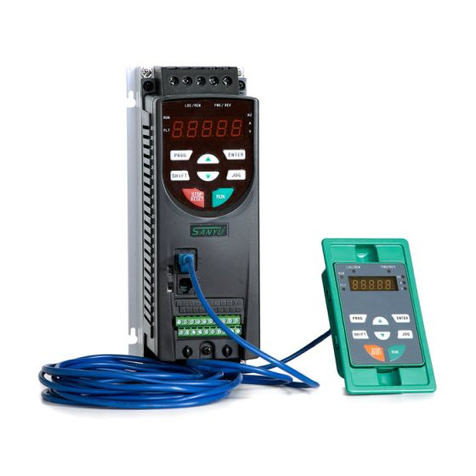
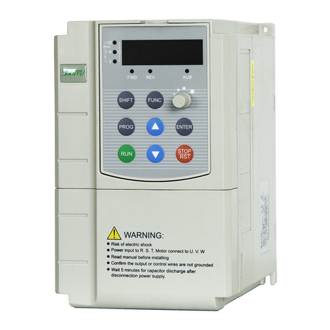
SANYU SY6600 User manual

SY6600 Vector Control Inverter User Manual
Contents
Chapter 1 Introduction to SY6600 Series Inverter .............................................................................. 3
1.1 Product Model Description.................................................................................................................. 3
1.2 Safe Precaution .................................................................................................................................. 4
1.3 Product Series.................................................................................................................................... 7
1.4 Product Specifications ........................................................................................................................ 8
1.5 Product Component Name ............................................................................................................... 11
1.6 Product Outline, Mounting Dimension, and Weight ........................................................................... 11
1.7 Operation Panel Outline and Mounting Dimension ............................................................................ 12
1.8 Braking Resistor Lectotype ............................................................................................................... 12
Chapter 2 Inverter Installation ........................................................................................................... 13
2.1 Environment for Product Installation ................................................................................................. 13
2.2 Mounting Direction and Space .......................................................................................................... 13
2.3 Removal and Mounting of Operation Panel and Cover ...................................................................... 14
Chapter 3 Wiring of Inverter .............................................................................................................. 16
3.1 Connection of the Product and Peripheral Devices ........................................................................... 16
3.2 Description of Peripheral Devices for Main Circuit ............................................................................. 17
3.3 Lectotype of mMain Circuit Peripheral Devices ................................................................................. 18
3.4 Product Terminal Configuration ......................................................................................................... 18
3.5 Functions of Main Circuit Terminal .................................................................................................... 18
3.6 Attention for Main Circuit Wiring ........................................................................................................ 20
3.7 Terminal Wiring ................................................................................................................................ 21
3.8 Functions of Control Circuit Terminals ............................................................................................... 22
3.9 Lectotype of Control Circuit Peripheral Devices ................................................................................ 23
Chapter 4 Using Instructions of Operation Panel ............................................................................ 24
4.1 Introduction to Operation Panel ........................................................................................................ 24
4.2 Descriptions of Indicators ................................................................................................................. 25
4.3 Description of Keys on Operation Panel............................................................................................ 25
4.4 Keypad Operating Status .................................................................................................................. 25
4.5 Panel Operation Method ................................................................................................................... 25
4.6 Parameter Display ............................................................................................................................ 28
4.7 Motor auto-tuning procedure............................................................................................................. 29
4.8 Running for the First Time ................................................................................................................ 30
Chapter 5 List of Parameters ............................................................................................................ 31
5.1 Function Parameter Table ................................................................................................................. 31
Chapter6 Detail Function Introduction ................................................................................................ 49
P0 Basic function parameters ................................................................................................................. 49
P1 Auxiliary function parameters 1 ......................................................................................................... 54
P2 Auxiliary function parameters 2 ......................................................................................................... 58

SY6600 Vector Control Inverter User Manual
P3 Motor parameters.............................................................................................................................. 63
P4 Dedicatd function for V/F control ..................................................................................................... 64
P5 Vector control funtion ........................................................................................................................ 66
P6 I/O I/O output terminal ....................................................................................................................... 70
P7 Analog input terminal function ........................................................................................................... 83
P8 Analog output terminal ...................................................................................................................... 85
P9 Program operating parameters .......................................................................................................... 87
PA PID parameter .................................................................................................................................. 90
Pb Traverse function .............................................................................................................................. 93
PC Communication and Bus control function .......................................................................................... 95
Pd Faults and protection parameters ...................................................................................................... 96
PE Factory reserved .............................................................................................................................. 99
PF Factory reserved ............................................................................................................................... 99
PH Display function ................................................................................................................................ 99
Chapter 7 Fault diagnosis and troubleshooting ............................................................................... 102
7.1 Fault query at fault.......................................................................................................................... 102
7.2 List of Fault and Alarm Information ................................................................................................. 102
7.3 Troubleshooting Procedures ........................................................................................................... 107
Chapter 8 Routine Repair and Maintenance ..................................................................................... 108
8.1 Routine Maintenance...................................................................................................................... 108
8.2 Periodic Maintenance ..................................................................................................................... 109
8.3 Component Replacement ............................................................................................................... 109
Appendix A Communication Protocol ............................................................................................ 110
Appendix B Control Mode Setting Process .................................................................................... 125

SY6600 Vector Control Inverter User Manual
www.sanyuacdrive.com
[键入文字]
Chapter 1 Introduction to SY6600 Series Inverter
1.1 Product Model Description
The digits and letters in the inverter model field on the nameplate indicate such information as the
product series, power supply class, power class and software/hardware versions.
SY6600 –0R4 G-4
Inverter Series NO. Inverter Type
G Constant Torque
Voltage No. P Fan Water Pump
220V 2
380V 4
NO. Adaptation
0R4G 0.4kw
0R7G 0.75KW
1R5G 1.5KW
2R2G 2.2KW
4R0G 4KW
Fig. 1-1 Inverter symbol description
1.2 Product Nameplate Description
Fig. 1-2 Inverter Nameplate
Note: The brake unit and RS485 communication unit are optional component, if needed,
MODEL: SY6600-2R2G-4
POWER:2.2KW
INPUT: 3PH AC380V 50Hz
OUTPUT:17A 0~400Hz

SY6600 Vector Control Inverter User Manual
www.sanyuacdrive.com
[键入文字]
please contact the factory previously.
1.2 Safety Precautions
Description of safety marks:
Danger: The misuse may cause fire, severe injury, even death.
Note: The misuse may cause medium or minor injury and equipment damage.
Use
DangerDanger
This series of inverter is used to control the variable speed operation of three-phase
motor and cannot be used for single-phase motor or other applications. Otherwise,
inverter failure or fire may be caused.
This series of inverter cannot be simply used in the applications directly related to the
human safety, such as the medical equipment.
This series of inverter is produced under strict quality management system. If the
inverter failure may cause severe accident or loss, safety measures, such as
redundancy or bypass, shall be taken.
Goods Arrival Inspection
NoteNote
If the inverter is found to be damaged or lack parts, the inverter cannot be installed.
Otherwise, accident may be caused.
Installation
NoteNote
When handling and installing the product, please hold the product bottom. Do not hold
the enclosure only. Otherwise, your feet may be injured and the inverter may be
damaged because of dropping.
The inverter shall be mounted on the fire retardant surface, such as metal, and kept far
away from the inflammables and heat source.
Keep the drilling scraps from falling into the inside of the inverter during the installation;
otherwise, inverter failure may be caused.
When the inverter is installed inside the cabinet, the electricity control cabinet shall be
equipped with fan and ventilation port. And ducts for radiation shall be constructed in
the cabinet.

SY6600 Vector Control Inverter User Manual
www.sanyuacdrive.com
[键入文字]
Wiring
DangerDanger
The wiring must be conducted by qualified electricians. Otherwise, there exists the risk
of electric shock or inverter damage.
Before wiring, confirm that the power supply is disconnected. Otherwise, there exists the
risk of electric shock or fire.
The grounding terminal PE must be reliably grounded, otherwise, the inverter enclosure
may become live.
Please do not touch the main circuit terminal. The wires of the inverter main circuit
terminals must not contact the enclosure. Otherwise, there exists the risk of electric
shock.
The connecting terminals for the braking resistor are ⊕2/B1 and B2. Please do not
connect terminals other than these two. Otherwise, fire may be caused.
The leakage current of the inverter system is more than 3.5mA, and the specific value of
the leakage current is determined by the use conditions. To ensure the safety, the
inverter and the motor must be grounded.
NoteNote
The three-phase power supply cannot connect to output terminals U/T1, V/T2 and
W/T3, otherwise, the inverter will be damaged.
It is forbidden to connect the output terminal of the inverter to the capacitor or LC/RC
noise filter with phase lead, otherwise, the internal components of the inverter may be
damaged.
Please confirm that the power supply phases, rated voltage are consistent with that of
the nameplate, otherwise, the inverter may be damaged.
Do not perform dielectric strength test on the inverter, otherwise, the inverter may be
damaged.
The wires of the main circuit terminals and the wires of the control circuit terminals shall
be laid separately or in a square-crossing mode, otherwise, the control signal may be
interfered.
The wires of the main circuit terminals shall adopt lugs with insulating sleeves.
The inverter input and output cables with proper sectional area shall be selected
according to the inverter power.
When the length of the cables between the inverter and the motor is more than 100m, it
is suggested to use output reactor to avoid the inverter failure caused by the overcurrent
of the distribution capacitor.
The inverter which equipped with DC reactor must connect with DC reactor between the
terminal of ○,+1、○,+2, otherwise the inverter will not display after power on.
Table of contents
Other SANYU Inverter manuals
Popular Inverter manuals by other brands

BARRON
BARRON EXITRONIX Tucson Micro Series installation instructions

Baumer
Baumer HUBNER TDP 0,2 Series Mounting and operating instructions

electroil
electroil ITTPD11W-RS-BC Operation and Maintenance Handbook

Silicon Solar
Silicon Solar TPS555-1230 instruction manual

Mission Critical
Mission Critical Xantrex Freedom SW-RVC owner's guide

HP
HP 3312A Operating and service manual