manuals.online logo
Brands
  1. Home
  2. •
  3. Brands
  4. •
  5. SANYU
  6. •
  7. Inverter
  8. •
  9. SANYU SY8000-0R7G-2 User manual

SANYU SY8000-0R7G-2 User manual

This manual suits for next models

38

Other SANYU Inverter manuals

SANYU SY6600 User manual

SANYU

SANYU SY6600 User manual

SANYU SY5000 Series Instruction Manual

SANYU

SANYU SY5000 Series Instruction Manual

Popular Inverter manuals by other brands

Omnik New Energy Omniksol-1.5k-TL user manual

Omnik New Energy

Omnik New Energy Omniksol-1.5k-TL user manual

Agilent Technologies 33250A user guide

Agilent Technologies

Agilent Technologies 33250A user guide

4-noks ZR-SWITCH-RC instruction manual

4-noks

4-noks ZR-SWITCH-RC instruction manual

V&T V5 Series user manual

V&T

V&T V5 Series user manual

Hon Turing HT-T-S1000-12 introduction

Hon Turing

Hon Turing HT-T-S1000-12 introduction

Metabo E 140 SP Plus Original operating instructions

Metabo

Metabo E 140 SP Plus Original operating instructions

BARRON EXITRONIX Tucson Micro Series installation instructions

BARRON

BARRON EXITRONIX Tucson Micro Series installation instructions

Baumer HUBNER TDP 0,2 Series Mounting and operating instructions

Baumer

Baumer HUBNER TDP 0,2 Series Mounting and operating instructions

electroil ITTPD11W-RS-BC Operation and Maintenance Handbook

electroil

electroil ITTPD11W-RS-BC Operation and Maintenance Handbook

Silicon Solar TPS555-1230 instruction manual

Silicon Solar

Silicon Solar TPS555-1230 instruction manual

Mission Critical Xantrex Freedom SW-RVC owner's guide

Mission Critical

Mission Critical Xantrex Freedom SW-RVC owner's guide

HP 3312A Operating and service manual

HP

HP 3312A Operating and service manual

Hoymiles HM-500T user manual

Hoymiles

Hoymiles HM-500T user manual

Nitecore SPM10 user manual

Nitecore

Nitecore SPM10 user manual

AEG Protect PV installation manual

AEG

AEG Protect PV installation manual

On Board TruePower Plus 1200MS owner's manual

On Board

On Board TruePower Plus 1200MS owner's manual

Plugreen PGM-200P-230 Installation and operation manual

Plugreen

Plugreen PGM-200P-230 Installation and operation manual

Fourgroup Easy use and Programming Handbook

Fourgroup

Fourgroup Easy use and Programming Handbook

manuals.online logo
manuals.online logoBrands
  • About & Mission
  • Contact us
  • Privacy Policy
  • Terms and Conditions

Copyright 2025 Manuals.Online. All Rights Reserved.

China Head Office of Technical Service
Manufacturer: Shanghai Sanyu Industry Co., Ltd.
Add.: No. 723, ShangCheng Rd, No.800, Shanghai, China
Fax +862151686158
P.C. 200120
HTTP://www.sanyuacdrive.com
E-Mail:[email protected]
Tel:+8613564535011
Foreword Contents
SY8000 series inverter is a new generation of high-performance vector inverter
that is developed by Sanyu, representing the future development trend.
SY8000 series inverter is a vector-control general inverter that is independently
researched, developed and produced by Shanyu, with the features of high quality,
multi functions, large low-frequency torque, ultra silencing, etc.. It realizes the fast
response of torque, strong load adaptability, stable operation, high accuracy,
perfect reliability, and improves the power factor and efficiency to the largest extent.
SY8000 series inverter provides the automatic parameter tuning, zero-servo
non-speed sensor, shift between vector control and V/F control, perfect user's
password protection, shortcut menu design, rotation speed tracing, built-in PID
controller, given and feedback signal disconnection monitoring and switchover,
load-loss protection, fault signal tracing, automatic restart against fault, built-in
braking unit, 25 fault protections, fault monitoring, abundant I/O terminals, various
speed setting ways, automatic voltage adjustment, wobble frequency control and
multi-speed control, it can meet the various loads' requirements of driving control.
If the keyboard is operated, LED displays the running data and fault code, and LCD
displays the Chinese state information and operation instructions, and copies the
parameters and delivers them; the background adjustment and monitoring software
can monitor the operation through the built-in standard RS485 interface; MODBUS
bus protocol and expansion card can be compatible with PROFIBUS, DeviceNet
and CANopen for field bus control. With the compact structure and unique style, the
inverter is designed and tested according to the international standard,
guaranteeing the reliability; in addition, its ample options are offered for your
various configuration selections.
This manual provides the instructions about the type selection, installation,
parameter setting, field adjustment, fault diagnose, daily maintenance, etc.. Before
using SY8000 series general vector inverter, please read this manual carefully, to
guarantee the correct use. The incorrect use may result in abnormal operation of
inverter, fault, reduction of service life, even human injury accident, therefore,
please read this manual repeatedly and fully understand it before using, and
operate strictly according to the instruction.
This manual is the attached document delivered with the inverter, please
preserve it well for future reference. Equipment-supporting customer shall deliver
this manual with the equipment to the end user.
Chapter 1 Safety points and precautions
1.1 Safety points
1.2 Precautions
Chapter 2 Product information
2.1 Denomination rules
2.2 Nameplate
2.3 Type of SY8000 series inverter
2.4 Technical specifications
2.5 Outline & installation dimension
2.6 Options
2.7 Daily maintenance
2.8 Guidance for selecting type
Chapter 3 Mechanical and electrical installation
3.1 Mechanical installation
3.2 Electrical installation
3.3 Connection way
3.4 Main circuit terminal and connection
3.5 Control terminal and connection
3.6 Solutions for EMC problems
Chapter 4 Operation and display
4.1 Introduction for operation and display interface
4.2 Operation rules
4.3 Methods for searching the state parameters
4.4 Fast adjustment
Chapter 5 Function parameters table
Chapter 6 Instruction for parameters
Chapter 7 Fault diagnose and solutions
Chapter 8 Maintenance
8.1 Daily maintenance
8.2 Regular maintenance
8.3 Change of wearable parts of inverter
8.4 Warranty for inverter
Chapter 9 Communication protocol
9.1 Contents of protocol
9.2 Application way
9.3 Bus structure
9.4 Instruction for protocol
9.5 Structure of communication frame
9.6 Description for command code and communication data
01
01
03
05
05
05
06
08
10
12
12
13
14
14
16
23
24
25
27
29
29
31
32
34
35
47
79
82
82
82
82
83
84
84
84
84
84
84
87
Chapter 1 Safety points and precautions Chapter 1 Safety points and precautions
1.1.7 In maintaining:
Don't install or operate the damaged inverter or the inverter lack of
the parts, otherwise, the accident will cause any personal injury.
Caution
1.1 Safety points:
1.1.1 Before installing:
1.1.2 In installing:
1.1.3 In wiring:
1.1.4 Before energizing:
1.1.5 After energizing:
1.1.6 In running:
This manual includes the operation instructions and attention.
In addition, please submit this manual to the end user.
Safety points
Before installing, operating, maintaining or examining the inverter, please read
this manual and attached documents carefully for correct use. Only you fully
understand the knowledge, safety information and all precautions about this
inverter, you can use it, in this manual, the safety points are classified into
“Danger” and “Caution”.
Caution
Danger The danger caused by the operation not according to the requirements
may result in severe injury, even the death.
The danger caused by the operation not according to the requirements
may result in medium or light injury and equipment damage.
Danger
Mount the inverter at the flame-retardant material (such as the metal),
and keep it away from the combustible material, otherwise, the fire will
be caused.
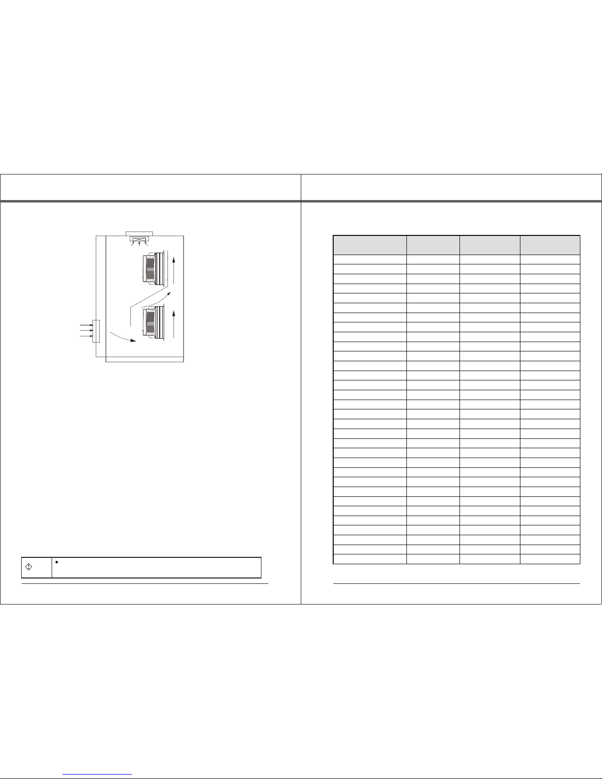
If more than two inverters are installed in a cabinet, please keep the
good heat emission for the installation position (refer to Chapter 3
Mechanical and electrical installation)
Don't let the conductor head or screw drop into the inverter, otherwise,
the inverter may be damaged.
The inverter shall be operated by the professional electrician,
otherwise, any electric shock will happen!
There must be a circuit breaker for isolating between inverter from
power supply, otherwise, the fire will happen!
Before connecting, please make sure that the power is switched
off, otherwise, you will suffer from the electric shock!
Please accord with the standard to perform the earthing operation,
otherwise, you will suffer from the electric shock!
Don't connect the input power line to the output terminals U, V and W,
otherwise the inverter will be damaged!
Make sure the provided circuit reaches EMC requirements and
local safety standard. Please refer to the suggestions in this manual
for the diameter of used conductor, otherwise, any accident will happen!
The braking resistor can't be directly connected between(+)
terminal and(-)terminal of DC bus, otherwise, the fire may
happen!
Please make sure that the supply voltage is consistent with the rated
voltage of inverter, the connection positions of input and output are
correct, the peripheral circuits have no short circuit, and all circuits
are connected firmly, otherwise, the inverter may be damaged!
Only the cover plate is closed, the inverter can be energized, otherwise,
you will suffer from the electric shock!
The inv erter h as been given t he with stand v oltage test bef ore
leaving the ma rket, so, it need n't to be tested aga in, otherw ise,
some accide nts may happe n!
After the inverter is energized, don't open the cover plate, otherwise,
you will suffer from the electric shock!
Never touch the inverter and peripheral circuits with the wet hands,
otherwise, the accident of electric shock will happen.
Don't touch the terminal of inverter, otherwise you will suffer from
the electric shock!
At the beginning of being electrified, the inverter can conduct the
safety check for the external strong current circuit automatically,
at this moment, don't touch the terminals U, V and W of inverter or
motor terminals, otherwise, the accident of electric shock will happen!
If needing the parameter identification, please notice the danger
that may be resulted from the motor rotation, otherwise, some injury
accidents will happen!
When the inverter is running, anything is not allowed to drop into,
otherwise, it may be damaged!
Never adopt the making and breaking methods for contactor to control
the start and stop of inverter, otherwise, it may be damaged!
Neve r mai nta in th e equi pme nt wh en th e pow er is sw itc hed o n,
othe rwi se, y ou ma y suf fer fr om th e ele ctr ic sho ck!
12
Danger
Danger
Caution
Caution
Danger
All periphery parts should be connected correctly according to
this manual, otherwise, any accident may happen!
Danger
Caution
Don't change the inverter parameters set by manufacturer randomly,
otherwise, the equipment may be damaged.
Danger
Caution
If selecting the restart function, please keep away from the mechanical
equipment, otherwise, the human injury accident may happen!
Never touch the cooling fan and discharge resistor to sound the temperature,
otherwise, you may be burned!
No layman is allowed to detect the signal when the equipment is running,
otherwise, the human injury or equipment damage may happen!
Danger
Only the “Charge” lamp of inverter goes out, the inverter can be maintained,
otherwise, you may be injured by the residual capacitance of capacitor!
No layman is allowed to maintain the inverter, otherwise, the human
injury or equipment damage may happen!
34
Chapter 1 Safety points and precautions Chapter 1 Safety points and precautions
1.2 Precautions
1.2.1 Examination for motor insulation
The motor should be given the insulation examination when it is used at first time
and reused after long-time no service and when it is checked regularly, to prevent
the inverter being damaged for poor insulation of motor windings. When conducting
the check for insulation, must separate the motor wires from the inverter. It is
suggested that 500V megohmmeter should be used to measure, the measured
insulation resistance should not be less than 5M.
1.2.2 Thermal protection for motor
When the rated capacity of motor doesn't match with that of inverter, especially,
the rated power of inverter is larger than that of motor, please adjust the related
motor-protection parameters inside the inverter or mount a thermal relay in front of
motor additionally to protect the motor.
1.2.3 Running at above power frequency
The inverter can provide the output frequency of 0~600Hz. If user wants it to
run at 50Hz above, please take the bearing capacity of mechanical device into the
consideration.
1.2.4 Vibration of mechanical device
The inverter may meet the mechanical resonant points of load device at some
power frequencies, which can be avoided through setting the hopping frequency
parameters inside the inverter.
1.2.5 Motor heat and noise
Because the inverter output voltage is PWM wave, including the certain harmonic,
the temperature rise, noise and vibration of motor will be increased slightly
compared with that when the inverter runs at power frequency.
1.2.6 Varistor or capacitor for improving the power factor on the output side
Because the inverter outputs PWM wave, if the capacitor for improving the power
factor or lightning-protection varistor is mounted on the output side, the
instantaneous over current is easily produced to damage the inverter, please don't
install them.
1.2.7 Contactors mounted at input and output terminals
If the contactor is mounted between the power supply and inverter input terminal
additionally, it is not allowed to control the start and stop of inverter. If necessary,
the interval of control should not be less than 1hour, because the frequent charge
and discharge will easily reduce the service life of capacitor that is in the inverter. If
the contactor is mounted between the output terminal and motor, please make sure
that the inverter performs the making and breaking operation when it has no output,
otherwise the inverter module will be damaged easily.
1.2.8 Use beyond the rated value
SY8000 series inverter should not be used beyond the permissible working
voltage specified in this manual, otherwise, the inverter parts will be damaged. If
necessary, please use the step-up or stepdown device for transformation treatment.
1.2.9 Changing three-phase input into two-phase input
SY8000 series three-phase inverter is not allowed to be used as two-phase one,
otherwise, the fault or damage of inverter will happen.
1.2.10 Lighting impact protection
The inverter has the lightning over current protection device, so, it has a certain
self-protection ability to resist the induction lightning. For the lighting frequent
occurrence area, a protection device should be mounted in front of inverter.
1.2.11 Altitude and derating use
In the area where the altitude exceeds 1,000m, the heat emission efficiency of
inverter gets bad for the tenuous air, therefore, it is necessary to reduce the
capacity. Please contact us for technology enquiry for this case.
1.2.12 Some special methods
If user needs the connection methods that are not specified in this manual, such
as the common DC bus, please contact us.
1.2.13 Attentions against the rejection of inverter
The electrolytic capacitor at main circuit and the one at the printed board may be
exploded when they are burned. The plastic part may produce the poisonous gas
when it is burned, therefore, they shall be treated as the industrial rubbish.
1.2.14 Applicable motor
1.2.14.1 The standard applicable motor is the four-pole squirrel cage
asynchronous induction motor. If your motor is not the abovementioned one, please
select the inverter according to the rated current of motor. If needing the drive of
permanent magnet synchronous motor, please contact us.
1.2.14.2 The cooling fan of non-frequency conversion motor is connected
coaxially with the rotator, the cooling efficiency of fan is lowered with the rotation
speed, therefore, a strong exhaust fan or frequency-conversion fan is mounted
against too much heat.
1.2.14.3 The inverter has provided the standard parameters of built-in motor,
according to the actual situations, please perform the motor parameter
identification or amend the default to accord with the actual value, otherwise, the
running efficiency and protection performance will be influenced.
1.2.14.4. If the cable or motor inner has the short circuit, the inverter will make
the alarm or it will be exploded, please perform the insulation short-circuit test for
the initially-installed motor and cable, and this test is also often conducted in daily
maintenance. Please pay attention to that when conducting this test, please switch
off the inverter and all tested parts.
Ch a p t er 2 P r o du c t i n f or m a t i o n Ch a p t er 2 P r o du c t i n f or m a t i o n
S2: 1AC 22 0 V
2:3AC220V
4:3AC380V
6:3AC690V
12:3AC1140V
Voltage class
Inverter type
G: Constant torque type
P: Fan and water pump type
F: Textile machine-purposed type
Z: Injection moulding
machine-purposed type
L: Wire drawing
machine-purposed type
C: Machine tool-purposed type
H: Heavy-duty type
0R7 :0 . 75 k W
7R5 :7 . 5k W
011 :1 1 kW
Power code
2. 1 D en o mi n a t io n r u l e s
2. 2 N am e pl a t e
Sh an y u
2. 3 T y p e of S Y 8 0 0 0 s e ri e s i n ve r t e r
In ve r te r
mo de l
SY8000-0R7G-2
SY8000-1R5G-2
SY8000-2R2G-2
SY8000-004G-2
SY8000-5R5G-2
SY8000-7R5G-2
SY8000-011G-2
SY8000-015G-2
SY8000-018G-2
SY8000-022G-2
SY8000-030G-2
SY8000-037G-2
SY8000-045G-2
In pu t
vo lt a ge
Th r e e - p ha s e
22 0 V v o l ta g e
ra n g e :
-1 5 % ~+ 1 5 %
R a t e d o u t
p u t p o w e r
(K W)
0.75
1.5
2.2
4.0
5.5
7.5
11.0
15.0
18.5
22.0
30.0
37.0
45
Rat e d in p ut
cur r en t
(A)
5.0
7.7
11
17
21
31
43
56
71
81
112
132
163
4.5
7
10
7
20
30
42
55
70
80
110
130
160
0.75
1.5
2.2
4
5.5
7.5
11
15
18.5
22
30
37
45
22 0V s e ri es
56
MOD LE : S Y8 0 00 - 7R 5 G- 4
POW ER : 7 .5 K W
INP UT : 3 PH A C 38 0 V 50 H z
OUT PU T : 17 A 0~6 00 H z
SHA NG H AI S A NY U E LE C TR O NI CS EQ UI P ME N T CO . ,L T D
Op e n - l o o p v e c t o r invert e r
Rat e d ou t p ut
cur r en t
(A)
App l ic a b le
mot o r
(KW )
2.4 Technical specifications
Basic spec.
Item
Max frequency
Carrier frequency
Resolution of input
frequency
Control mode
Starting torque
Speed regulation range
Speed stabilization accuracy
Overload capacity
Torque increase
V/F curve
Acc./dec. curve
DC brake
Jogging control
Multi-speed running
Built-in PID
Automatic voltage
regulation (AVR)
Common DC bus function
JOG Ke y
Wobble frequency
control for spinning
Timing control
Spec.
600.00Hz
1.0~15.0KHz
Digital setting: 0.01Hz
Analog setting: Max frequency ×0.1%
Vector control without PG (SVC)
V/F control
Type G: 0.5Hz/150%
Type P: 0.5Hz/100%
1:100
±0.5%
Type G: 150% of rated current for 60s; 180% of rated current for1s;
Type P: 120% of rated current for 60s; 150% of rated current for1s;
Automatic torque increase
Manual torque increase 0.1%~30.0%
Two modes:
Straight line type
2.0 power
Stra igh t-li ne o r S -cur ve acce ler atio n an d
deco rati on m ode ; two kin ds o f acc ele rati on
and d ecel era tion time ; ra nge o f acc eler ati on
and d ecel era tion time : 0. 1~360 0.0s
DC braking frequency:0.0Hz~10.00Hz; braking
time: 0.0~50.0s; braking operation current:
0.0~150.0%
Jo gg in g fre qu e n c y ra ng e : 0. 00 H z~P 0. 13 ;
jo gg in g ac ce l er at io n an d de ce le r at io n ti me :
0. 0~3 60 0. 0 s
8-segment speed control
Realizing the process closed loop control system conveniently
When the mains voltage makes the change, it can
automatically keep the output voltage constant.
Realizing the functions of common DC bus for many inverters
Programmable key: Jog/forward & reverse rotation
switchover/clearing UP/DOWN setting
Multi triangular wave frequency control functions
Timing control function: Setting time range 0~65535h
Individual function
SY8000-0R7G-4
SY8000-1R5G-4
SY8000-2R2G-4
SY8000-004G/5R5P-4
SY8000-5R5G/7R5P-4
SY8000-7R5G/011P-4
SY8000-011G/015P-4
SY8000-015G/018P-4
SY8000-018G/022P-4
SY8000-022G/030P-4
SY8000-030G/037P-4
SY8000-037G/045P-4
SY8000-045G/055P-4
SY8000-055G/075P-4
SY8000-075G/090P-4
SY8000-090G/110P-4
SY8000-110G/132P-4
SY8000-132G/160P-4
SY8000-160G/185P-4
SY8000-185G/200P-4
SY8000-200G/220P-4
SY8000-220G/250P-4
SY8000-250G/280P-4
SY8000-280G/315P-4
SY8000-315G/350P-4
SY8000-350G/400P-4
0.75
1.5
2.2
4.0/5.5
5.5/7.5
7.5/11.0
11.0/15.0
15.0/18.5
18.5/22.0
22.0/30.0
30.0/37.0
37.0/45.0
45.0/55.0
55.0/75.0
75.0/90.0
90.0/110.0
110.0/132.0
132.0/160.0
160.0/185.0
185.0/200.0
200.0/220.0
220.0/250.0
250.0/280.0
280.0/315.0
315.0/350.0
350.0/400.0
3.4
5.0
5.8
10.0/15.0
15.0/20.0
20.0/26.0
26.0/35.0
35.0/38.0
38.0/46.0
46.0/62.0
62.0/76.0
76.0/90.0
90.0/105.0
105.0/140.0
140.0/160.0
160.0/210.0
210.0/240.0
240.0/290.0
290.0/330.0
330.0/370.0
370.0/410.0
410.0/460.0
460.0/500.0
500.0/580.0
580.0/620.0
620.0/670.0
2.5
3.7
5.0
9.0/13.0
13.0/17.0
17.0/25.0
25.0/32.0
32.0/37.0
37.0/45.0
45.0/60.0
60.0/75.0
75.0/90.0
90.0/110.0
110.0/150.0
150.0/176.0
176.0/210.0
210.0/253.0
253.0/300.0
300.0/340.0
340.0/380.0
380.0/420.0
420.0/470.0
470.0/520.0
520.0/600.0
600.0/640.0
640.0/690.0
0.75
1.5
2.2
4.0/5.5
5.5/7.5
7.5/11.0
11.0/15.0
15.0/18.5
18.5/22.0
22.0/30.0
30.0/37.0
37.0/45.0
45.0/55.0
55.0/75.0
75.0/90.0
90.0/110.0
110.0/132.0
132.0160.0
160.0/185.0
185.0/200.0
200.0/220.0
220.0/250.0
250.0/280.0
280.0/315.0
315.0/350.0
350.0/400.0
38 0 V系列
78
In ve r te r
mo de l
Inp u t
vol t ag e
R a t e d o u t
p u t p o w e r
(K W)
Rat e d in p ut
cur r en t
(A)
Rat e d ou t p ut
cur r en t
(A)
App l ic a b le
mot o r
(KW )
Thr e e-
pha s e
380 V
vol t ag e
ran g e:
- 1 5 % ~
+ 1 5 %
Ch a p t er 2 P r o du c t i n f or m a t i o n Ch a p t er 2 P r o du c t i n f or m a t i o n
FWDREV
REM
LOC
Z H
A
V
RUN
FLT
U V W P+ BR
SUN ON
DP2 0 1 A
220 -240V 0 .125A
11 1 21 3 14 15 16 1 7 18 1 9 20
1 2 3 4 5 6 7 8 9 10
2.5 Outline & installation dimension
Display Panel
Operation Panel
Control Board Box
Radiator
Mounting Hole At Bottom
Brand
External Keyboard Interface
Control Terminal
Main Circuit Terminal
Fig. 2-1 Inverter outline diagram
2.5.1 Outline diagram
Fig. 2-2 Inverter outline & installation dimension diagram
Display and operation
Input/output characteristics Environment
Earthing screw
B
D
Continued
R S T P+ P -
U V W P+ B R
I-O
U-O
I-I
U-I
FWD RE V REM
LOC
HZ
A
V
RUN
FLT
EN TE R
JO G
PR OG
SH IF T
1 2 3 4 5
6 7
8 9 10
11 12 13 14 15 16 17 18 19 20
E-P
SR- 485
910
Ch a p t er 2 P r o du c t i n f or m a t i o n Ch a p t er 2 P r o du c t i n f or m a t i o n
Running command
channel
Frequency source
Input terminal
Output terminal
LED
LCD
Parameter locking
Protection function
Option
Service location
Altitude
Ambient temp.
Humidity
Vibration
Storage temp.
Three channels: Operation panel setting, control terminal
setting, serial communication port setting
Digital setting, analogy voltage setting, analog current
setting, serial port setting, etc.
Two analog input terminals, hereinto, No. 4 terminal is
used for voltage input, and No. 5 terminal is used for
voltage or current input.
One open collector output
Two relays output
One analog terminal, 0/4~20mA or 0~10V available
for it, can realize the output of analog quantities such
as setting frequency and output frequency.
Displaying parameters
Option, displayed in Chinese
Preventing other persons setting the parameters
Short-circuit protection, input/output phase-failure protection,
over-current protection, under-voltage protection, over-voltage
protection, over-load protection, over-heat protection, etc.
LCD operation panel, multi-function input/output expansion
card, braking component, communication wire, etc.
Indoors, free from direct sunlight, dust, corrosive gas,
combustible gas, oil mist, water vapor, drip or salt, etc.
Lower than 1,000m
-10℃~+40℃(at 40℃~50℃, please use it by derating)
Less than 95%RH,no water condensation.
Less than 5.9m/s 2
-20℃~+60℃
Communication Interface
2.6 Options2.5.2 Dimensions of mounting hole
SY8000-0R7G/1R5P-4
SY8000-1R5G/2R2P-4
SY8000-2R2G/004P-4
SY8000-004G/5R5P-4
SY8000-5R5G/7R5P-4
SY8000-7R5G/011P-4
SY8000-011G/015P-4
SY8000-015G/018P-4
SY8000-018G/022P-4
SY8000-022G/030P-4
SY8000-033G-4
SY8000-037P-4
SY8000-037G/045P-4
SY8000-045G/055P-4
SY8000-055G-4
SY8000-075P-4
SY8000-075G/090P-4
SY8000-090G/110P-4
SY8000-110G/132P-4
SY8000-132G/160P-4
SY8000-160G/185P-4
SY8000-185G/200P-4
SY8000-200G/220P-4
SY8000-220G/250P-4
SY8000-250G/280P-4
SY8000-280G/315P-4
SY8000-315G/400P-4
0.75G/1.5P
1.5G/2.2P
2.2G/4P
4G/5.5P
5.5G/7.5P
7.5G/11P
11G/15P
15G/18.5P
18.5G/22P
22G/30P
30G
37P
37G/45P
45G/55P
55G
75P
75G/90P
90G/110P
110G/132P
132G/160P
160G/185P
185G/200P
200G/220P
220G/250P
250G/280P
280G/315P
315G/400P
B
(mm)
210
210
416
532
750
910
H
(mm)
175
170
190
247
300
330
343
410
800
W
(mm)
102.5
174
253
324
468
490
505
713
410
D
(mm)
260
260
430
549
770
940
1140
1700
1900
5
7
9
9
11
G.W.
(kg)
3
6
11
17
62
75
180
250
380
A
(mm)
95
165
180
250
300
300
M o d e l o f i n v e r t e r
(G: Constant-torque load
P: Fan a nd wate r
pump load)
Applicable motor
(KW)
Mounting
hole dia.
)mm(
Instruction
2.7 Daily maintenance of inverter
2.7.1 Daily maintenance
The effect of temperature, humidity, dust and vibration leads to the aging of inner
parts of inverter,potential fault or reduction of service life of inverter. Therefore, it is
necessary to implement the daily and regular maintenance for inverter.
After switching off the power, if the filter capacitor still has the high
voltage, the inverter can't be maintained immediately, only waiting
the charge lamp goes out ,and the bus voltage measured by the
multimeter should not exceed 36V, the maintenance can be performed.
11 12
157 152.5 90 173 52
77.5
Ch a p t er 2 P r o du c t i n f or m a t i o n Ch a p t er 2 P r o du c t i n f or m a t i o n
Name
Built-in braking unit
Built-out braking unit
MODBUS communication wire
PROFIBUS-DP bus card
DeviceNET bus card
CANopen bus card
Peripheral LCD operation panel
Extension wire of peripheral
LCD operation panel
The single-phase 0.75~2.2KW of built-in braking
unit, needing a built-out braking resistor additionally.
The three-phase 0.75~15KW of built-in braking
unit, needing a built-out braking resistor additionally.
Three-phase built-out braking unit of 18.5KW and above
RS485 communication interface
PROFIBUS-DP bus interface
DeviceNET bus interface
CANopen bus interface
External LCD display and operation keyboard
Provision according to the requirements of site.
Caution
Daily inspection items
1)Check whether motor makes the abnormal sound in running.
2)Check whether the motor has the vibration in running.
3)Check whether the installation environment of inverter makes the
change.
4)Check whether the cooling fan of inverter works normally.
5)Check whether the inverter is too hot.
Daily cleaning
Keep the inverter clean.
Clear away the dust on the surface of inverter and prevent the dust entering into
the inner, especially the metallic dust.
Effectively clear away the oil pollution of cooling fan of inverter.
2.7.2 Regular inspection
Please regularly examine the part that is difficult to be checked in running.
Regular inspection items
1)Check the air duct, and conduct the regular cleaning.
2)Check whether the screw is slack.
3)Check whether the inverter is corrosive.
4)Check whether the terminal has the track of arc discharge.
13
Parts name
Fig. 3-1 Installation gap
Above 100mm
Above 50mm
Fan exhaust
Above 100mm
14
R S T P+ P -
U V W P+ B R
I-O
U-O
I-I
U-I
FWD RE V REM
LOC
HZ
A
V
RUN
FLT
EN TE R
JO G
PR OG
SH IF T
1 2 3 4 5
6 7
8 9 10
11 12 13 14 15 16 17 18 19 20
E-P
SR- 485
5)Main circuit insulation test
Reminder: When testing the insulation resistance with the megohmmeter (DC 500V
megohmmeter), separate the main circuit lines from the inverter. Never use the insulation
ohmmeter to test the insulation of control circuit. HV test needn't to be performed, because
this test has been finished before the inverter leaves factory.
2.7.3 Change of wearable parts of inverter
The wearable parts of inverter include the cooling fan and electrolytic capacitor for
filtering, their service life is closely related to the service environment and maintenance
status. In general, their life is shown as follows:
Fan
Electrolytic capacitor
Service life
2~3 years
4~5 years
User can determine the age limit according to the running time.
1) Cooling fan
Possible cause for damage: Bearing abrasion and blade aging.
Examination standard: Check whether the fan blade has the crack, whether the fan has
the abnormal vibration when it is started.
2)Electrolytic capacitor for filtering
Possible cause for damage: Bad quality of input power, higher environment temperature,
frequent jump of load, aging of electrolyte.
Examination standard: Leakage of liquid, projection of safety valve, and test of static
capacitance and insulation resistance,
2.7.4 Storage of inverter
After user purchases the inverter, please pay attention to following points for temporary
storage and long-time storage.
1)Put the inverter with the original package into our packing case when it is
stored.
2)The long-term storage will result in degradation of electrolytic capacitor, so,
the inverter must be electrified once every two years, the electrified time should be
5hours at least, the input voltage should rise to the rated value step by step with
the voltage regulator.
2.8 Guidance for selecting type
Two control modes are available: Common V/F control and SVC control.
When selecting the inverter, first, you must identify the system technical requirements of
frequency-conversion speed regulation, application location of inverter, load characteristics,
etc., and take the applicable motor, output voltage, rated output current, etc. into the
consideration, then to select the machine type at your request and determine the running
way.
Basic principle: The rated load current of motor should not exceed the rated current of
inverter, in general, select the inverter according to the applicable motor capacity that is
specified as the manual, please compare the rated current of motor with that of inverter. The
overload capacity of inverter makes actually sense to the starting and braking operation.
Whenever the inverter has the short-time over load, the load speed will be changed. If the
speed accuracy is demanding, please take a higher class into account.
Fan and water pump type: The overload capacity is undemanding. Because the load
torque is directly proportional to the square of speed, the load (except the rose fan) is very
light when it runs at a low speed. And, these loads have no special requirements on the
rotation accuracy, so, the square torque V/F is selected.
Constant-torque load: Many loads such as the extruder, agitator, conveyer belt, plant
trolley, crane translating mechanism have the constant-torque characteristics, however,
their rotation speed and dynamic performance are undemanding. Accordingly, multi-
segment V/F operation way is available when choosing the type.
The controlled object has a certain dynamic and static state requirement. The strong
mechanical characteristics are required for this type of load when it runs at a low speed, to
meet the control system requirements of dynamic and static indicators. SVC control way is
available.
Chapter 3 Mechanical and electrical installation
3.1 Mechanical installation
3.1.1 Installation environment
1)Environment temperature: The ambient temperature has a large impact on
the service life of inverter, the running environment temperature of inverter should
not exceed such temperature range (-10℃~50℃).
2)The inverter is installed on the surface of flame-retardant object, it should
have the enough space for ventilation, because it produces much heat easily when
working. And, it should be vertically installed at the mounting rack with the screw.
3)Please install it in the firm area without easy vibration occurrence. The
vibration should not be more than 0.6G. Especially, it should be kept away from
the punch.
4) It is installed in the area free from the direct sunlight, dampness and drip.
5)It is installed in the area free from the corrosive, flammable, explosive gas,
etc..
6)It is installed in the location free from the oil pollution, much dust and
metallic dust.
3.1.2 Prompt for installation environment
Monomer installation diagram
Note: When the inverter power is not larger than 22KW, the dimension A may not
be taken into consideration. When larger than 22KW, the dimension A should be
larger than 50mm.
Chapter 3 Mechanical and electrical installationCh a p t er 2 P r o du c t i n f or m a t i o n
SY8000-0R7G-S2
SY8000-1R5G-S2
SY8000-2R2G-S2
SY8000-004G-2
SY8000-5R5G-2
SY8000-7R5G-2
SY8000-011G-2
SY8000-015G-2
SY8000-018G-2
SY8000-022G-2
SY8000-030G-2
SY8000-037G-2
SY8000-045G-2
SY8000-0R7G-4
SY8000-1R5G-4
SY8000-2R2G-4
SY8000-004G/5R5P-4
SY8000-5R5G/7R5P-4
SY8000-7R5G/011P-4
SY8000-011G/015P-4
SY8000-015G/018P-4
SY8000-018G/022P-4
SY8000-022G/030P-4
SY8000-030G/037P-4
SY8000-037G/045P-4
SY8000-045G/055P-4
16
20
32
40
63
100
125
160
160
200
200
200
250
10
16
16
25
25
40
63
63
100
100
125
160
200
2.5
4
6
6
6
10
25
25
25
35
35
35
70
2.5
2.5
2.5
4
4
6
6
6
10
16
25
25
35
10
16
20
25
32
63
95
120
120
170
170
170
230
10
10
10
16
16
25
32
50
63
80
95
120
135
Danger
Top and bottom installation diagram
Fig. 3-2 Installation of multi inverters
When disassembling the lower cover plate, please avoid its drop,
otherwise, the equipment may be damaged.
SY8000-075G/090P-4
SY8000-090G/110P-4
SY8000-110G/132P-4
SY8000-132G/160P-4
SY8000-160G/185P-4
200
250
315
400
400
630
35
70
70
95
150
185
170
230
280
315
380
450
Model of inverter
15 16
Note: When the inverter is installed vertically, please mount a heat-insulated
baffler shown as fig. 3-2.
Please pay attention to the following points about heat emission when performing
the mechanical installation.
1)The inverter should be installed vertically, which enables the heat to emit
upwards easily, but it should not be mounted reversely. If many inverters need to
be installed in a cabinet, you'd better install them side by side. If the inverters
need the top and bottom installation, please mount a heat-insulated baffler shown
as fig. 3-2.
2)Make sure the inverter has the enough space for heat emission, the
installation space is shown as fig. 3-1. However, when laying it, please consider
the heat emission of other parts in the cabinet.
3)The mounting rack must be made of the flame-retardant material.
4)For the area with full metallic dust, it is suggested the installation outside the
cabinet of radiator should be adopted, and, the space inside the full-seal cabinet
should be as large as possible.
3.1.3 Dismounting and mounting of lower cover plate
SY8000 series inverter of 22KW below adopts the plastic enclosure, exposed
main circuit terminal, without disassembling the cover plate.
SY8000 series inverter of 30KW above adopts the sheet metal enclosure, the
lower cover plate of sheet metal enclosure needs to be disassembled, just slack the
screw of lower cover plate directly.
3.2 Electrical installation
3.2.1、 Circuit breaker, cable and contactor
Circuit breaker (A) Input/output wire
(Copper wire and cable) Contactor (A)
Chapter 3 Mechanical and electrical installationChapter 3 Mechanical and electrical installation
SY8000-055G/075P-4