Sapa Alumax ProLine PL60 User manual

105 Broadway St. Belvue, KS 66407
Phone: 800-669-9867 Fax: 800-393-6699
www.onyxcollection.com
PL80-0522
800-643-1514
www.alumaxshowerdoor.com
by Sapa
INSTALLATION INSTRUCTIONS
ProLine PL80
HEAVY FRAMELESS BARN DOOR
BATH ENCLOSURE

Page 2 of 12
N
PL80 PARTS LIST
A Wall Mount Anchor
B Wall Mount Block
C 1/4 x 2½” Truss Head Screw
D Header Bar
E Wall Mount Sleeve
F Fixed Panel
G Bottom Channel Anchor
H Drip Vinyl
I Bottom Channel
J Bottom Channel Screws
L Center Guide
M Center Guide Anchor
N Optional Wall Jamb
O Center Guide Screws
P Door Panel
Q Roller Back Plate
R Back Plate Sleeve
S Back Plate Gasket
T Mid Plate Gasket
U Mid Plate
V Roller Plate
W Roller Screw
X Anti-Jump
Y Anti-Jump Screw
Z Glass Mount Threaded Rod
AA 5/16" x 3/4" Socet Cap Screw
BB Glass Mount
CC Glass Mount Washer
DD Glass Mount Bushing
EE Glass Mount Cap
FF Stopper
GG Stopper Screw
HH Wall Mount Set Screw
JJ Bulb Vinyl
KK Panel Seal
N P
N 1/8” Setting Blocks
P 1/16” Setting Blocks

Page 3 of 12
Notes:
–This is a two person installation.
1
2
3
4
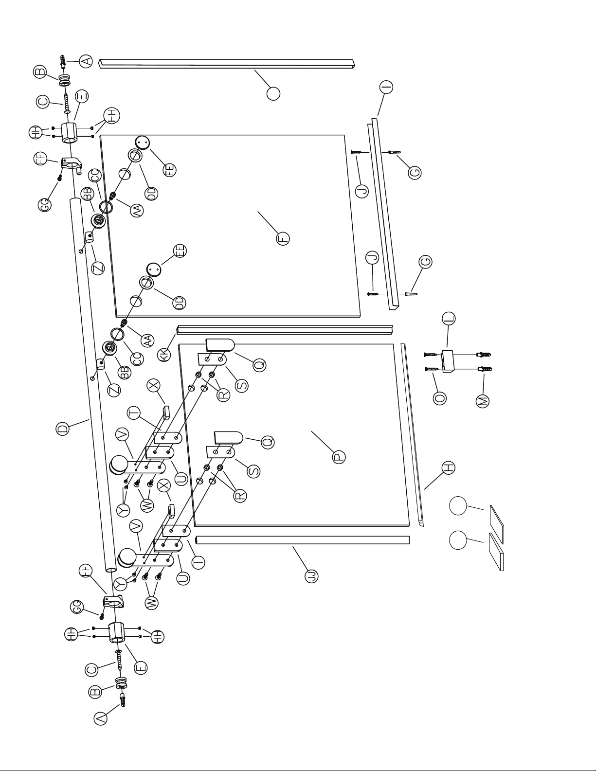
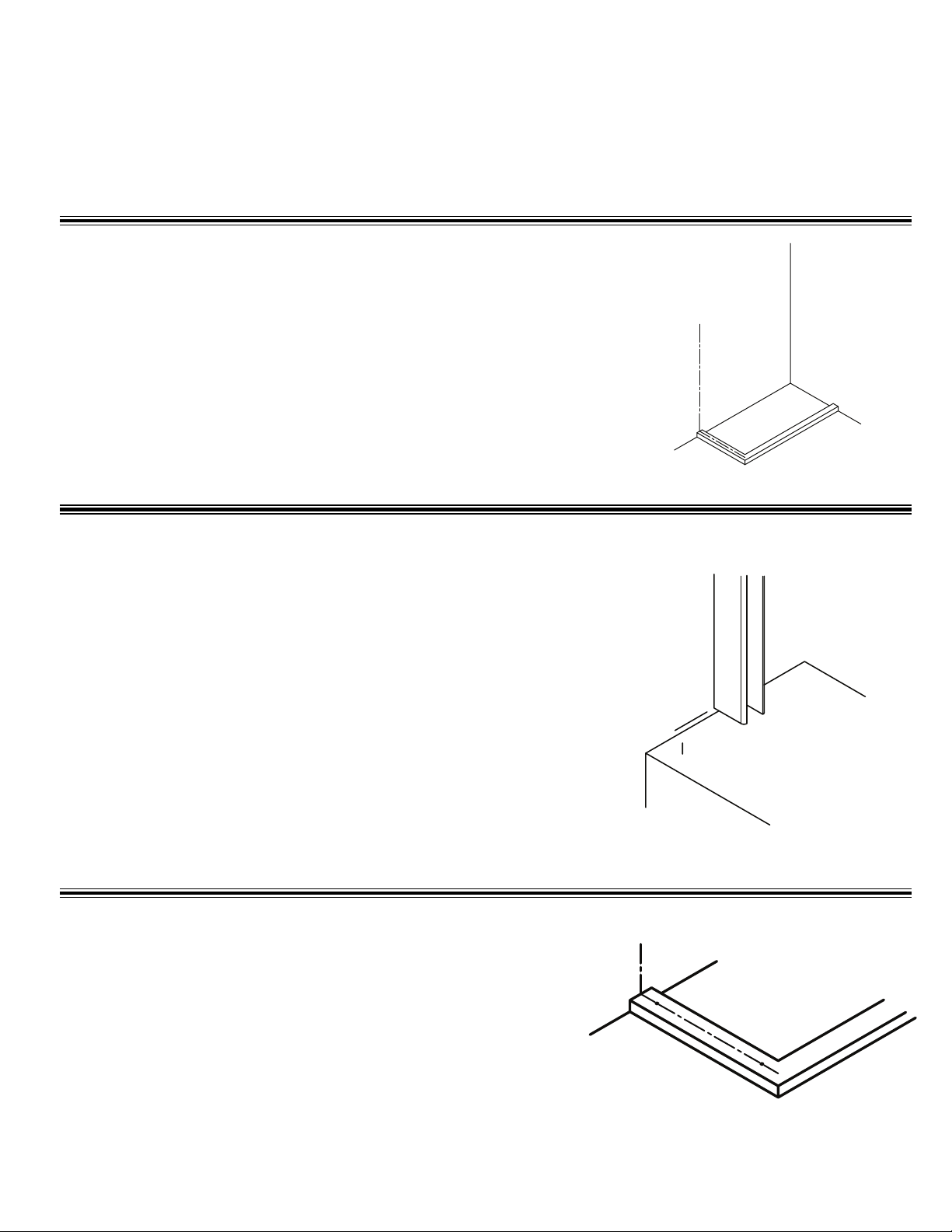
FOOT PRINT - The width of the Door unit's base is 2 1/16"
Consider these measurements before drilling.
Fixe Panel (F)
15/16”
1
7/8”
Total width of shower door unit
From door panel centers
Outside
of curb
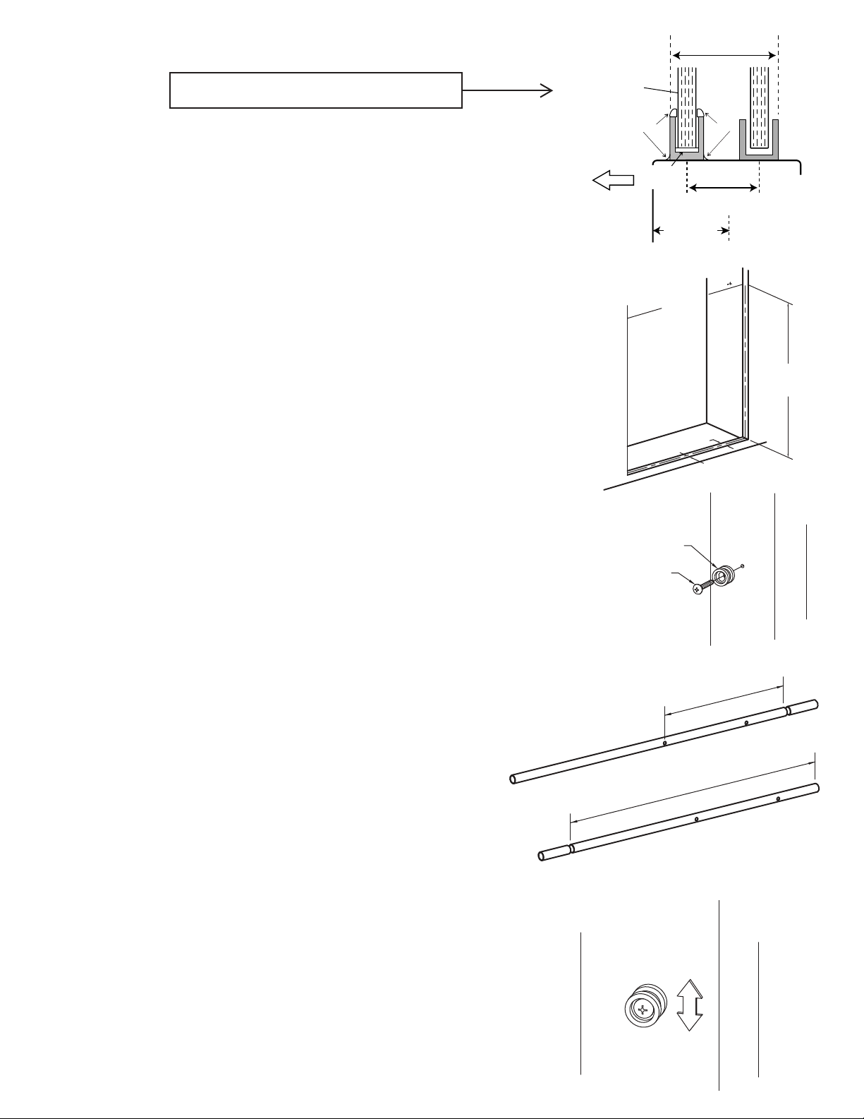
Establish Centerlines
c
L
1
1/2” Min.
of sliding door
All marks made on tile, marble or berglass should be made lightly in
pencil so they can be removed after the installation is complete.
An optional method is to use masking tape on the walls and sill that can be
removed as the installation progresses.
• The centerlines of the door must be established on the shower sill and on the
walls as well. (See diagram top of page)
• Measure the width of the shower sill and mark the centerline down the middle.
(This needs to be at least 1½” from outside of curb edge)
• Transfer the centerline to the walls using a level. Mark Header Bar [D] location
at 2” less than the unit height, on the centerline. (Unit height on Box Label)
• Measure, and write down, the distance between the two Wall Mount marks.
Note: Unit Height is Stationary Panel Height Plus ¼"
MEASURE
UNIT HEIGHT
- 2”
SILL÷2
CENTERLINE
SILL
Wall Mount Block
Wall Mount Screw
FIXED PANEL
WIDTH - 2 3/8”
UNIT WIDTH - 1 3/4”
Bar Mount – Drill the Wall Mount holes 5/16”. Insert the Wall Anchors
[A] fully into the holes. Place the Wall Mount Blocks [B] against the
wall with the counter bore to the middle of the enclosure. Using the 1/4 x
2½” Truss head screws [C], attach the Wall Mount Block to the wall, with the
slot in a vertical position and the screw centered in the block.
Bar Length - Measure the width of the xed glass panel [F]. Subtract
2 3/8” from that dimension. Measure from the center of the middle
hole in the bar to the xed panel end of the bar and cut that end o (The
xed panel end is the one with the second hole in it). Now subtract
1 3/4” from the measurement taken in step 1, which is the overall
width of the shower opening at the top. Then take that measure
from the newly cut end of the bar to the uncut end and cut that
end o of the bar.
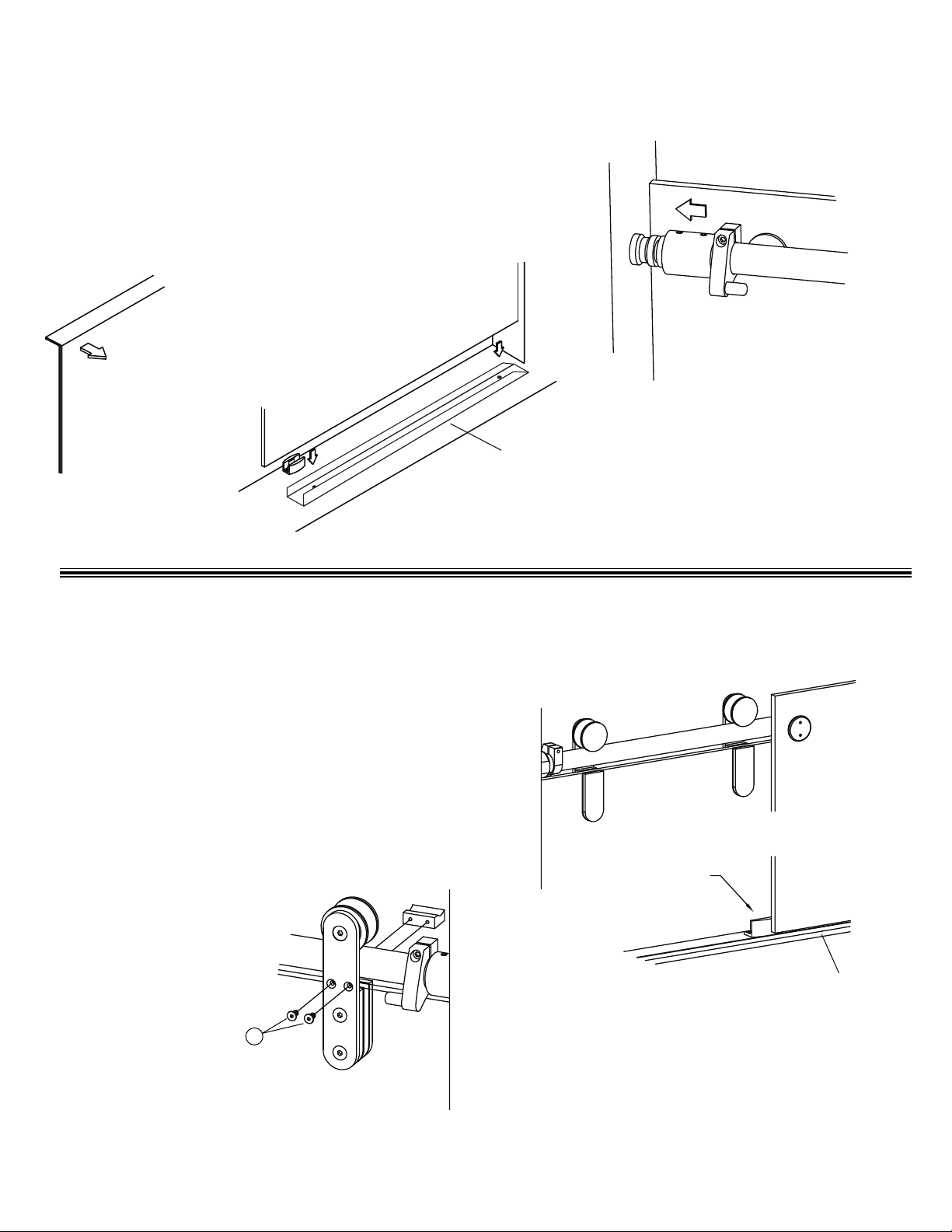
Level the Bar – Temporarily place the Wall Mount Sleeves [E] on each
end of the Header Bar. Align the Header Bar with the Wall Mount.
Place Block, and slide the Wall Mount Sleeves over the Wall Mount Blocks.
a level on the center of the Header Bar and check for level. If needed the
Wall Mount Blocks can be raised, or lowered to make the Header Bar level.
Once leveled, remove the Header Bar from the Wall Mount Blocks, and the
Wall Mount Sleeves from the Header Bar.
SILICONE SILICONE
CLEAR
SETTING
BLOCKS

Page 4 of 12
6
5
Center of door unit
N
Stationary panel Bottom Channel
C
L
Minimum 1 ½” from outside edge
of curb to the of the door
• Mark the center point (side to side) of the sill along the centerline established
in step one.
• Make a line 15/16” outside of the centerline.
• Place Bottom Channel over this Line & drill a hole through both predrilled
holes in the Bottom Channel.
• Clean the area around the holes and put a little silicone into each hole.
• Press the Anchors [G] into the holes until fully seated.
• Put a little silicone into each anchor.
• Install the Bottom Channel on the sill.
Mount the SC-658 Wall Jamb [N] to the wall, usng the screws and
anchors provided. The opening of the wall jamb should be lined up
with the bottom channel.
MIDPOINT OF C
L
OUTSIDE
15 / 16” 15 / 16”
OUTSIDE
OUTSIDE
MIDDLE OF C
L
1 1/2”
Center Guide – Make a mark on the centerline approximately 1
1/2” toward the door side. Place the Center Guide [L] on the
new mark, centered on the mark. Mark the center of the attachment
holes and, remove the Center Guide. Drill two 1/4” holes at the
center guide attachment locations. Clean the area around the
holes and put a little silicone into each hole. P ress the Center Guide
Anchors [M] into the holes until the lip is ush with the sill. Put a little
silicone into each anchor. Mount the Center Guide with the Center
Guide Screws [O].

Page 5 of 12
7
8
OUTSIDE
Door Panel – Mount the roller assemblies to the Door Panel
[P], making sure that the Roller Back Plate [Q], the Back Plate
Sleeve [R] and the Back Plate Gasket [S] are to the outside. The
Back Plate Gasket has the large holes. Place a Mid Plate Gasket
[T] and the Mid Plate [U] on the inside of the glass and secure
the Roller Plate [V] to the entire assembly with the Roller Screws
[W]. Set aside the Anti-Jump [X] piece and Anti-Jump Screws [Y]
until after the door has been mounted to the header Bar. Install
your handle option at this time. Install the sweep [H] with the deector
leg to the inside of the door, then, place the Door Glass inside the
shower enclosure with the Rollers facing out and the handle so that
it is on the side of the enclosure that the door will strike against.
CAUTION: Make sure that you set the Door Glass on something
so that the glass and/or the oor of the enclosure are not damaged.
Cardboard packing material works ne.
Prole of Sweep [H]
Deector leg
Inside of Shower
Load the Bar – (The header may come pre-loaded).
Using a thin rod, or straightened wirecoat hanger, push the Glass
Mount Threaded Rods [Z] into the end of the Header Bar and line
one up with each hole in the bar. Put a 5/16” x 3/4” Socket Cap
Screw [AA] through the Glass Mount [BB] and snug it down into a
rod inside the Header Bar (DO NOT TIGHTEN).
Place a Glass Mount Washer [CC] on top of the Glass Mount [BB].
Repeat for the other hole. Place a Glass Mount Bushing
[DD] on each of the Glass Mount Caps [EE]. Line the middle hole of the
bar up with the hole located 1 1/2” from the edge of the Fixed Panel.
Thread the Wall Mount Caps onto the Wall Mounts until Snug (DO
NOT TIGHTEN) Place a Stopper [FF] on both ends of the Header
Bar with the rubber bumper on each facing the middle of the bar
(oriented as shown). Slide them toward the middle and snug the
Stopper Screw [GG] (DO NOT TIGHTEN). Slide a Wall Mount
Sleeve [E] on both ends of the Header Bar, and snug one Set
Screw [HH] (DO NOT TIGHTEN).
NOTE: There are two at surfaces on the Wall Mount Sleeve, one is
on the end of the sleeve and that goes towards the end of the
Header Bar, and the other is on the side of the sleeve and that one
goes between the Fixed Glass and the Header Bar.
U
T
V
W
X
RS
Q
D
Z
EE
AA
GG
FF
E
CC
BB
DD
1.5”
FLAT SURFACE

Page 6 of 12
9
10
Fixed Panel Installation - Lift the Fixed Panel and set it in
the Bottom Channel with the edge as tight to the wall as
possible. Loosen the Set Screws in the wall mount sleeves
and slide them over the Wall Mount Blocks. Snug the Set
Screws into the block (DO NOT TIGHTEN).
INSIDE
CENTER GUIDE
CHANNEL
Door Panel Installation – Lift the Door Panel [P]
and place the rollers on the bar, making sure to
get the bottom edge of the Door Glass into the Center
Guide. To adjust the door glass height, Adjustments must
be made to the Bar height. Adjustments can be made in
the wall mount blocks (See step 4). Once you have the
Header Bar set as you want it, and the Fixed Panel posi-
tioned correctly, tighten the Wall Mount Set Screws, then
the Glass Mount Screws and Caps. CAUTION: Do not
remove both Glass Mount Caps at the same time. Install
the anti-Jump [X] and Anti-Jump Screws [Y] on both Roller
Assemblies.
STATIONARY
PANEL CHANNEL
Y

Page 7 of 12
11
12
13
14
BULB VINYL
PANEL SEAL
Seal Installation – Cut the Bulb Vinyl [JJ] and the
Panel Seal [KK] to the vertical length of your Door
Glass. Press the Bulb Vinyl on the strike side of the Door
Glass and the Panel Seal on the other, below the Header
Bar. A small amount of silicone can be used between the
glass and seal if you like.
Set the Stops – Move the door to the closed
position. Slide the Stopper [FF] over until it touches
the bottom of the roller on the strike side of the door,
making sure that the bottom of the stopper will clear the
top of the door glass. Tighten the Stopper Set Screw [GG].
Move the door to the open position with the handle 1/4” -
1/2” from hitting the xed panel. Slide the other stopper
over until it just touches the bottom of the roller on the xed
side of the door. Tighten the Stopper Set Screw.
Finishing Up – Make sure that all fasteners are tight.
Clean all exposed marks you made on the sill and
walls of the shower stall. Clean the glass panels.
Using Onyx Adhesive. 24 hours for any silicone to completely cure, before
using your new Alumax Shower Door.

Page 8 of 12
800-643-1514
www.alumaxshowerdoor.com
by Sapa
INSTALLATION INSTRUCTIONS
Barn Door
OPTIONAL
RETURN PANEL
105 Broadway St. Belvue, KS 66407
Phone: 800-669-9867 Fax: 800-393-6699
www.onyxcollection.com

Page 9 of 12
PL RETURN PARTS LIST
A SC-658 Wall Jamb
B Wall Jamb Screw
C Wall Jamb Anchor
D Bottom Channel Anchor
F Bottom Channel
G Bottom Channel Screw
I Glass Return Panel

Page 10 of 12
Notes:
This is a two person installation.
1
2
All marks made on tile, marble or berglass should be made lightly in
pencil so they can be removed after the installation is complete. An
optional method is to use masking tape on the walls and sill that can be
removed as the installation progresses.
Establish Centerline – Lightly, mark the centerline of the Return Panel
on the sill and up the wall of the shower stall.
Mark the Wall Jamb Location – Place the SC-658 Wall Jamb [A]
against the return wall with the holes lined up with the centerline
marked in Step 1. Mark the center of all 3 holes on the centerline.
Remove the wall jamb and drill all 3 locations for the Wall Anchors [C]
you are using to mount the wall jamb. Clean the holes. Silicone, and
insert the wall anchors, but do not install the wall jamb at this time.
3
Return Channel Location - Place he Bottom Channel on the
centerline. Mark the center of both nodes on the centerline.
Remove the channel and dril both marks with 1/4” drill bit. Clean
the holes and sill of debris, squirt a little silicone into the holes
and insert the Glass Clip Anchors [D].

Page 11 of 12
4
5
Channel Installation – Put a little silicone in the glass anchors.
Then, install the Channel using the Screws [G] provided.
Wall Jamb Installation – Mount the SC-658 Wall Jamb
[A] to the return wall.

Page 12 of 12
6
7
Return Panel Installation – Run a bead of silicone in the center of
the the SC-658 Wall Jamb, and into the Bottom Channel. Then,
orient the Glass Return Panel so that the return mount hole is toward
the front of the enclosure. Slide the vertical edge of the glass into the
siliconed SC-658 wall jamb. Set the bottom edge of the glass into the
Siliconed Bottom Channel.
Note: Use setting Blocks to line the Return-mount-hole up with the
Correct Header Bar Height established in Step 1 of the
Barn Door Instructions.
Install the return mount through the hole in the
return glass panel.
Things to Remember – There will only be one wall mount bracket used. The other support for the header bar
being the returnmount (step 8).
This manual suits for next models
2
Table of contents
Popular Shower Cabin manuals by other brands

American Bath Factory
American Bath Factory Sistine Stone Double Corner-Hdm installation guide

Kermi
Kermi RA P TWD Series installation instructions

RAVAK
RAVAK SKCP4 Free-80 installation instructions

Omnires
Omnires Bronx S2050 Installation and Maintenance

Welltime
Welltime Vigo 1027173 Installation instruction

KOLO
KOLO GEO 6 Installation