manuals.online logo
Brands
  1. Home
  2. •
  3. Brands
  4. •
  5. Sargent
  6. •
  7. Door Lock
  8. •
  9. Sargent 8200 User manual

Sargent 8200 User manual

INSTALLATION INSTRUCTIONS FOR
8200 Lever with Freewheeling Escutcheon Trim FE
FOR ASSISTANCE, CALL SARGENT AT 1-800-727-5477 or www.sargentlock.com
Parts List Description
1. Inside Lever
2. Spring
3. Set screw
4. Through-bolt Screws (2)
(1/4" - 20 x 1-3/4)
5. Inside Escutcheon Plate
6. Screws & Lockwashers (2)
(#8-32 x 5/8")
7. Adapter & Plate Assy.
8. Lever spindle
9. Outside Escutcheon
Assembly
10. Cylinder
11. Screws (2) (#8-32 x 1/4")
12. Front Plate
13. Lockbody screws (2)
(#12 x 1-1/4")
14. Lockbody
25 Function Shown — For hole locations of other functions, see template page 4
Patent pending and/or patent
www.assaabloydss.com/patents
A7334G 1
Insert lockbody into mortise
cutout. Hold loosely in place
with (2) lockbody screws.
Do not tighten screws fully
at this time.
A. With outside lever
horizontal, carefully insert
the mounting posts through
the door and lockbody.
Make sure the spindle is
properly engaged in the
lock. Outside escutcheon
assembly should be flush
with door surface.
If cylinder is not included in
this function, proceed to step 3.
B. Screw cylinder into
lockbody until flush with
escutcheon face.
Install Lockbody Outside Escutcheon Assembly
3
1
2
5
4
11
12
10
14
6
78
Inside
of
Door
Outside
of
Door
13
9
12
Copyright© 2005, 2008, 2010, 2016, Sargent Manufacturing Company, an ASSA ABLOY
Group company. All rights reserved. Reproduction in whole or in part without the
express written permission of Sargent Manufacturing Company is prohibited.
Lockbody
Screws
Inside Adapter & Plate Assembly
A7334G
2
3
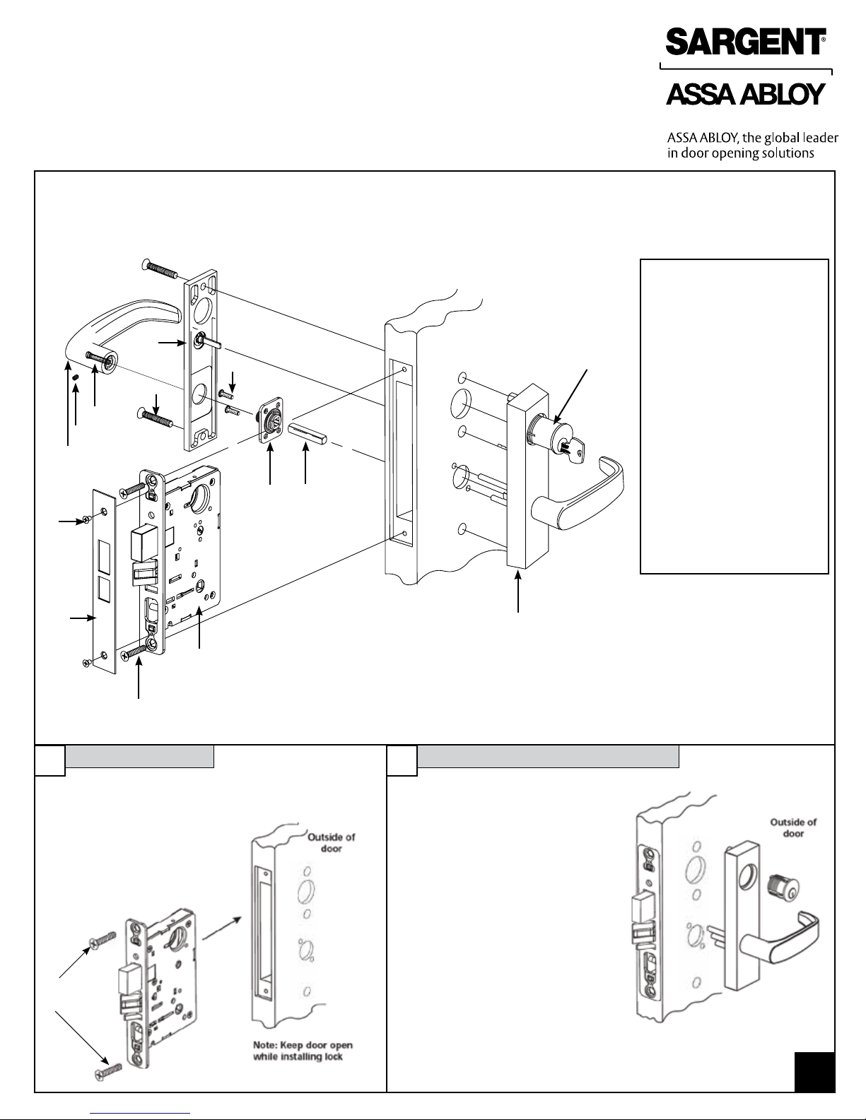
A. Slide spindle (8) into lockbody hub
B. Slide adapter & plate assembly (7) over
spindle and secure with two #8-32 screws (6)
(do not tighten)
C. Tighten lockbody screws (13) on edge of
the door
D. Tighten both #8-32 (6) screws, securing
adapter & plate assembly
E. Position inside Escutcheon (5) and secure
with two 1/4-20 x 1-3/4" screws (4)
F. Place inside lever (1) horizontally onto lever
spindle (8). Hold lever firmly against the
escutcheon.
G. Use the 1/8" Allen wrench to tighten the set
screw (3) securely. Set screw should seat in
the groove of the inside adapter (7).
H. Pull on lever to verify set screw is seated
properly.
Copyright© 2005, 2008, 2010, 2016, Sargent Manufacturing Company, an ASSA ABLOY Group company. All rights reserved.
Reproduction in whole or in part without the express written permission of Sargent Manufacturing Company is prohibited.
INSIDE
INSIDE
OUTSIDE
OUTSIDE
LEFT HAND
LEFT HAND
REVERSE
BEVEL
RIGHT HAND
RIGHT HAND
REVERSE
BEVEL
DOOR HANDS DETERMINED FROM OUTSIDE
DOOR HANDING
Red color indicates locked
side of door
Locking piece
slot
Lock
front
Latch
Hub
Note: Red surface of locking piece must face secure side of door.
To rotate locking piece:
1.Position lockbody with red surface of locking piece visible
2.Insert blade type screwdriver into locking piece slot to rotate
locking piece
3.Push locking piece toward back of lock body and rotate 180°
until RED surface shows on opposite side
Note: Beveled surface of latch must face strike. The
deadlatch is self adjusting. To change hand of latch:
1. Insert screwdriver blade
into the spade shaped
slot
2. Rotate screwdriver 90º to push latchbolt out of the lock
case, until back of latchbolt clears lock front. Then
rotate latchbolt 180º allowing it re-enter the lockbody.
(Note: Latch can not be unscrewed)
How to Change Hand of Lock
Note: Functions 04, 06, 13, 17 and 31 require the following,
before the locking piece can be rotated:
(a) Remove the Green catch screw
(b) Rotate hub to make straight
(c) Rotate locking piece for required hand
(d) Red surface faces locked side of door
(e) Rotate hub to the original 45 degree position as shown
on lock case
(f) Reinstall the Green catch screw
7
46
13
4
5
Cylinder retainer
access hole
12
11
3
1
I. With the cylinder flush to the
escutcheon face, rotate cylinder
to make the keyway vertical. This
ensures that the cylinder retainer
fork will line up with the notch on
the side of the cylinder.
J. Secure the cylinder with a #2
Phillips screw driver, using the
cylinder retainer access hole.
K. Test key & cylinder to verify the
lock is functioning correctly.
L. Secure Outside Front (12)
with two #8-32 screws (11) to
the lockbody.
Changing Hand Of Trim
A7334G 3
1. Loosen screw (1) and remove interlocking assembly (2).
See Figure A.
2. Unscrew the lower through-bolt stud (11) with a 3/8" wrench.
Remove mounting plate (6) and mounting posts. Switch
mounting posts (7) so they occupy the opposite positions on
the mounting plate (6)
3. Note the original position of the extension spring (16) and
lower plate (9) in the escutcheon (14). Unhook the extension
spring from pin (13).
4. Remove spring (16), lower plate (9) and locking hub (8)
assembly together.
5. Detach extension spring (16) from lower plate (9) and locking
hub assembly (8). Flip lower plate on locking hub assembly
spindle so that the spring hole is on the opposite side.
Reattach hook end of spring to lower plate.
6. Unscrew cap screw w/spacer (12) using 5/32" Allen wrench.
Move to opposite hole and tighten firmly.
7. Rotate lever to position shown in Figure E for desired hand.
8. Tighten retaining nut (10) firmly by hand and then back off one
notch until pattern shown in Figure C appears.
9. Attach bottom of spring (16) (closed loop) to pin (13). Hold
lever horizontal while inserting locking hub assembly (8) and
lower plate (9) into retaining nut (10).
10. Refer to Figure E: Position hub (4) for required function and
hand, checking that spindle (5) is vertical. Note position of
interlocking assembly Hook when positioning hub. Reposition
spindle as shown in Figure D if necessary.
11. Place the interlocking assembly (2) into the escutcheon and
attach the bottom hook to the locking hub (8) as shown in
Figure B. Secure in place with screw (1).
Caution: Check that locking hub (4) moves freely by
rotating the hub spindle (5). If not, check that bottom
hook is engaged in locking hub (8).
12. Insert and secure mounting plate and mounting posts to
escutcheon with lower through-bolt stud (11).
Figure D
Figure A
2 Interlocking
assembly
1
7
6
7
8
9
10
3
4
5
15
14
16
13 12
Bottom
hook Figure B Figure C
RIGHT
HAND
SHOWN
TOOLS REQUIRED
Phillips screw driver
Wrench 3/8"
Allen wrench 5/32"
Function
05, 16, 36, 37, 38, 65
Function
24, 25, 26, 35, 39, 40, 66
11
Figure E
Note: 04, 17 & 31
function locks, the
outside lever is always
freewheel and inactive,
the key is used to
retract the latchbolt
Rotate and
press in
Pull out
Interlocking
assembly hook
Spindle
Hub
ALWAYS WEAR EYE PROTECTION WHILE WORKING
Copyright© 2005, 2008, 2010, 2016, Sargent Manufacturing Company, an ASSA ABLOY Group company. All rights reserved.
Reproduction in whole or in part without the express written permission of Sargent Manufacturing Company is prohibited.
R.H. L.H.
R.H.R. L.H.R.
R.H. L.H.
R.H.R. L.H.R.
4A7334G
Copyright ©2005, 2008, 2010, 2016, Sargent Manufacturing Company, an ASSA ABLOY Group company. All rights reserved.
Reproduction in whole or in part without the express written permission of Sargent Manufacturing Company is prohibited.
4X
.422
27/64"
4X
.625
5/8"
2X
2.469
2-15/32"
2X
3.875
3-7/8"
2X
1.765
1-49/64"
2X
6.688
6-11/16"
INSIDE
OF DOOR
3
5
1
7
C
L
OF BEVEL
9
9
6.500
6-1/2"
8.031
8.000
8-1/32"
8"
7.250
7-1/4"
3.625
3-5/8"
4.000
4"
DIM "B"
AA
C
L
OF LEVER
OR KNOB
MOUNTING SCREWS
2X DRILL AND TAP FOR
#12-24 x .750 [3/4"] SCREW
C
L
OF DOOR
2X
2.750
BACKSET
2-3/4"
2X
1.797
1-51/64"
DIM "C"
.375
3/8"
OUTSIDE
OF DOOR
4
6
82
C
L
OF STRIKE
C
L
OF
LOCKBODY
C
L
OF BEVEL
5
9
9
.219
7/32"
DIM "A"
SECTION A-A
C
L
OF BEVEL
REQUIRED HOLES
FUNCTION
123456789
1.125
[1-1/8"]
DIA.
1.125
[1-1/8"]
DIA.
1.375
[1-3/8"]
DIA.
1.375
[1-3/8"]
DIA.
.750
[3/4"]
DIA.
.750
[3/4"]
DIA.
.250
[1/4"]
DIA.
.250
[1/4"]
DIA.
.562
[9/16"]
DIA.
04, 37
05, 24, 25
17, 26, 38, 39, 40
31, 35, 36
65, 66
RELEASE DATE
TEMPLATE
NO
.
100 Sargent Drive New Haven, CT 06511
Manufacturing Company
TEMPLATE: MORTISE LOCK
8200 SERIES: (FREE WHEELING)
METAL DOOR
4500
J
NOTES:
DENOTES HOLE REQUIRED FOR FUNCTION LISTED. (CHECK TABLE BEFORE CUTTING HOLE.)
1.
REFER TO TRIM TEMPLATE FOR ADDITIONAL HOLE REQUIREMENTS.
2.
SUITABLE REINFORCEMENTS REQUIRED FOR METAL DOORS.
3.
FOR DETAILS, SEE STRIKE TEMPLATE 7063.
4.
FOR WOOD DOORS SEE TEMPLATE A7323.
5.
DETAIL OF SUGGESTED DOOR-CUT

Other Sargent Door Lock manuals

Sargent P2 PASSPORT 1000 User manual

Sargent

Sargent P2 PASSPORT 1000 User manual

Sargent Profile Series User manual

Sargent

Sargent Profile Series User manual

Sargent P2 PASSPORT 1000 User manual

Sargent

Sargent P2 PASSPORT 1000 User manual

Sargent P2 PASSPORT 1000 User manual

Sargent

Sargent P2 PASSPORT 1000 User manual

Sargent Passport 1000 PG User manual

Sargent

Sargent Passport 1000 PG User manual

Sargent P2 PASSPORT 1000 User manual

Sargent

Sargent P2 PASSPORT 1000 User manual

Sargent Assa Abloy IN120 User manual

Sargent

Sargent Assa Abloy IN120 User manual

Sargent P2 PASSPORT 1000 User manual

Sargent

Sargent P2 PASSPORT 1000 User manual

Sargent 7800 Series User manual

Sargent

Sargent 7800 Series User manual

Popular Door Lock manuals by other brands

Gainsborough Contemporary Series quick start guide

Gainsborough

Gainsborough Contemporary Series quick start guide

Yale Conexis L1 manual

Yale

Yale Conexis L1 manual

Assa Abloy Corbin Russwin Access 800 TCAC2 Series Programming instructions

Assa Abloy

Assa Abloy Corbin Russwin Access 800 TCAC2 Series Programming instructions

Lock Focus Euclid D Pull Handle quick start guide

Lock Focus

Lock Focus Euclid D Pull Handle quick start guide

ABH 6500 Series installation instructions

ABH

ABH 6500 Series installation instructions

Dormakaba SVP Mounting instructions

Dormakaba

Dormakaba SVP Mounting instructions

Digilock Numeris Versa Standard user guide

Digilock

Digilock Numeris Versa Standard user guide

effeff 843-3 Installation and mounting instructions

effeff

effeff 843-3 Installation and mounting instructions

McGrathLocks MLR2 manual

McGrathLocks

McGrathLocks MLR2 manual

Abus AWLX PRO Installation instructions and user guide

Abus

Abus AWLX PRO Installation instructions and user guide

Smarti BIOSLIM user manual

Smarti

Smarti BIOSLIM user manual

Lloyd's LC-1342 Quick installation guide

Lloyd's

Lloyd's LC-1342 Quick installation guide

Simons Voss PegaSys Door Handle 4.1 Panic bar quick guide

Simons Voss

Simons Voss PegaSys Door Handle 4.1 Panic bar quick guide

Itec iHTL 03 instruction manual

Itec

Itec iHTL 03 instruction manual

AXCEZE AX-M600L manual

AXCEZE

AXCEZE AX-M600L manual

Iseo X1R Smart user manual

Iseo

Iseo X1R Smart user manual

Videosec AC-MF1W user manual

Videosec

Videosec AC-MF1W user manual

Dorex 9500 Series installation instructions

Dorex

Dorex 9500 Series installation instructions

manuals.online logo
manuals.online logoBrands
  • About & Mission
  • Contact us
  • Privacy Policy
  • Terms and Conditions

Copyright 2025 Manuals.Online. All Rights Reserved.