SAT-Kabel SPM 6R User manual

Chemnitzer Straße 11 .09217 Burgstädt
Satelliten- und Kabelfernsehanlagen/Industrievertretung GmbH
SAT
Kabel
-
®
OPERATING INSTRUCTIONS
device version v1.26 or higher
Level- und Return path tester
SPM 6R

2
This instruction has been performed to the best of our knowledge. Developments and
technical amendments are subject to change without notice.
Topical made operating instructions in a PDF format can also downloaded from our
Internet homepage ( ).www.sat-kabel.de
We thank you for buying of a product of the company SAT-Kabel
This operating instructions shall help you to understand the functions of the instrument
and to ease its use. If you have questions about this instrument or suggestions for
further improvements, please get in touch with us.
®.

3
Content
1. General
4. Preparation level and return path test ........................................................
.......................................................................................................4
2. Scope of delivery ........................................................................................4
3. Functional elements....................................................................................4
4
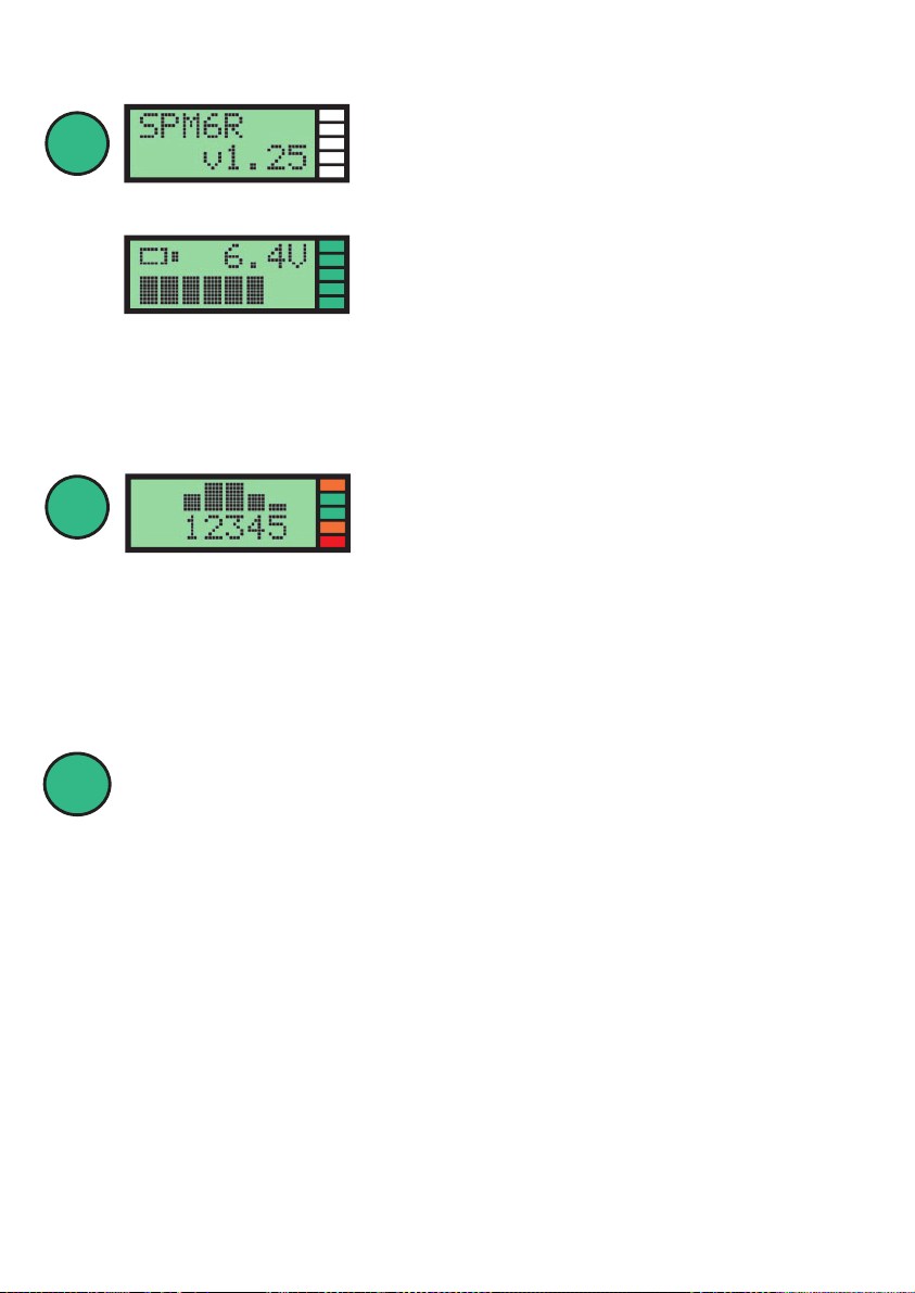
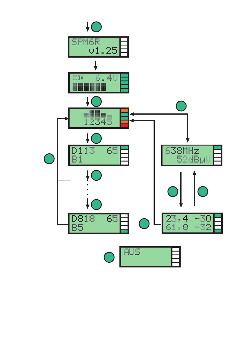
5. Switch on the unit.......................................................................................5
6. Forward scan and evaluate.........................................................................5
6.2 Evaluation...................................................................................................6
7. Single channel display and evaluation........................................................6
7.1 Channel designations .................................................................................7
7.2 Single channel selection and manual reading of the level values...............7
9. Switch off the unit.......................................................................................8
10. Charging the ....................................................................................9
11. Technical data and facilities........................................................................9
Guarantee............................................................................................................15
6.1 SCAN with LED and bar display...................................................................5
8. Return path test..........................................................................................8
8.1 Downstream ...............................................................................................8
8.2 Upstream ....................................................................................................8
device
12. Functional scheme ....................................................................................10
13. Cleaning and maintenance .......................................................................10
Annex ..................................................................................................................11
A Adjustment of the downstream frequency................................................12
B Adjustment of the channel list .................................................................13
B.1 B.1 Set-up procedure ................................................................................13
B.2 The 4 adjustment positions.......................................................................14
B.2.1 Channel selection .....................................................................................14
B.2.2 Activating and assigning a channel ..........................................................14
B.2.3 Define the channel as a digital channel by specifying the
center frequency.......................................................................................14
B.2.4 Setting the level correction for digital channels........................................14
B.2.5 To leave the programming mode ..............................................................15

4
F socket
Display
Control button
LEDs
Charging socket
3. Funktional elements
1. General
2. Scope of delivery
4. Preparation level and return path test
The processor-controlled level tester is by its compact and handy design the
ideal device for fast level control in the NE 4 - primarily at system outlets.
This level tester has been developed for the field sales staff (media consultant) of Kabel
Deutschland for easy checking of analog and digital offers of the cable connection at the
subscriber.
SPM 6R
1× incl. NiMH-battery (6 V/300 mAh)
1× Operating instruction
1× Mains adapter 230 V
1× Car charging cable 12 V
1× Connecting cable with F connectors
1× Adapter (F socket to IEC Socket)
AC
DC
SPM 6R
The attached connecting cable with F-connectors must be screwed by hand with one of
two identical F-connector firmly onto the F-socket of the level tester. The use of other
connecting cable is not recommended.
On free F-connector of the connecting cable is then the attached adapter
(F-socket to IEC F-socket) with its F-socket to screw firmly. Then the level tester is to
connect with the screwed connection cable by plugging the IEC socket on the TV port
of the system outlet.
The level tester is to connect with the screwed connection cable by
plugging the F socket on the DATA port of the system outlet.
Level test |
Return path test |

5
>1 s
short
short
5. Switch on the unit
1| By short press of button once the device is turned on. It first ap-
pears for about 1 s the device type and version number of
the implemented device software (v1.26 or higher)
Then the display shows the battery charge status with
the voltage value and is with an extra horizontal bar
graph visualized. Typical display value is in the range
between 5.8 V and 7.2 V. If the voltage of the battery is
below 5.5 volts, the unit switch off automatically and is only ready for operation again at
connection of a charging device.
With the switching on takes place an LED test. In this case all LEDs have to light for 1
s simultaneously red, then yellow and at last green.
2 immediate subsequent short key press| At the device
remains on, it appears the bar graph (BK, scan) The SPM will
immediately start a scan and displays the result in the
display and the LEDs.
If the key is not pressed after switching on a second time, then switches the SPM 6R once
again off - also after 2 minutes of inactivity.
Continue with item 6
or
Switchover to
return path test, item 8
Here it is also possible to switch into the mode return
path test. For this the key is to press again longer than
1s.
6. Forward scan and evaluate
6.1 SCAN with LED and bar graph
In SCAN mode the level tester searches continued for five consecutive sections for any
free selectable reference channels in the CATV frequency range. The five frequency
ranges and the assignment of the LEDs are printed on the measuring device.
On the basis of the set limits in the level tester for the expected minimum level at
with the SCAN a constantly evaluation takes place. The evaluation
result for each frequency range is indicated by the respective LED (red / yellow / green).
The display for the entire partial area depends in each case to the worst level value in
the corresponding reference channels
system outlets

6
range: 1
2
3
4
5
bar graph high:
large LED green
middle LED yellow
small LED red
comply with
comply with
comply with
LED/bar graph range frequency range (channels)
1B1
2B2
3B3
4B4
5B5
... 300 MHz ( D113, S11, S20)
300 ... 470 MHz ( D378, D442, D466)
470 ... 614 MHz ( D538, D610)
614 ... 750 MHz ( D746 )
750 ... 862 MHz ( D818 )
A not yet existing channel allocation above 470 MHz or 614 MHz in the network level 3
(lack of network expansion and lack of channel allocation) leads to corresponding red
LED displays. In these cases cannot still be closed from the »bad« indicator to the
expansion state or a 862 MHz capability of the house distribution system.
The figure below shows the evaluation of the scan by LED and a five-part vertical bar
graph. In this case represents the height of the bar the evaluation result in the associ-
ated range.
At the same time shows the top LED (LED 1) the evaluation result of sub-range 1, the
next LED the sub-range 2, etc. If the scanned reference channels of the sub-ranges were
found "all right", the respective LED lights up green, otherwise, the display depends on
the worst channel in each.
CAUTION: If the button for more two minutes is not operated, switches
the level testers automatically off and must be restarted by
short press again the button. (see item 5)
6.2 Evaluation
signal format/ level
modulation type incorrect / not suitable near limit okay
PAL (standard B/G) 57 dB(µV) 57 ... 59 dB(µV) 60 ... 77 dB(µV)
>80 dB(µV) 78 ... 80 dB(µV)
DVB-C 64 QAM 47 dB(µV) 47 ... 49 dB(µV) 50 ... 67 dB(µV)
>73 dB(µV) 68 ... 73 dB(µV)
DVB-C 256 QAM 53 dB(µV) 53 ... 55 dB(µV) 56 ... 73 dB(µV)
>79 dB(µV) 74 ... 79 dB(µV)
LED colour red yellow green
<
<
<

7
>1 s
short
short
Further switching
next channel
switch back to the
mode SCAN
7.2 Single channel selection and manual reading of the level values
7.1 Channel designation
7. Single channel display and evaluation
By again short press changes the display in the "single-
channel evaluation".
In the display now three items are visible:
Top left, appears the name of the first read reference channel, here, » «, right
above the level in dB(μV), here » « and bottom left the corresponding sub-range, here
» «, in which the reference channel is located and is used for its evaluation the level
value.
D114
65
B1
Furthermore visualizes the top LED (LED 1) in addition the results display with red,
yellow or green, as defined in Section 6.1 (page 5).
S
K
D
= analogue special
channel
= analogue channel
= digital channel
Within the single-channel display the channels with the
adjacent additions are marked at the beginning. The
term » « thus represents the otherwise so designa-
ted digital channel.
D114
By a further short keystroke changes the display always to the next higher reference
channel.
After the possible 10 reference channels were tested, the unit changes at the next short
press back in the mode » «. The device allows also by long keystroke (>1 s) the
early changes into the mode » «. It must not be tested all 10 channels.
SCAN
SCAN
Furthermore visualizes the top LED (LED 1)also here in addition the results
display with red, yellow or green, as defined in Section 6.1 (page 5).
Press the button .briefly
Press the key than 1 s. It takes place the switch
into the mode » « (LED-evaluation).
longer
SCAN

8
2s
short
short
8.2 Upstream
8. Return path test
8.1 Downstream
9. Switch off the unit
Switch back to
Scan (bar graph display)
CAUTION: If the button for more two minutes is not operated, switches
the level testers automatically off and must be restarted by
short press again the button. (see item 5)
Was pressed in the menu Scan – see item 5, under 2 | – the
button longer (>1 s), so appears this display of the te-
lemetry frequency (downstream) with an associated
level. The LED indicates data reception:
Green – data received
Red – no data received
This is the second display of return path tests. You will see
the return path attenuation at two frequencies (up-
stream) between system outlet and CMTS. Additionally
to the LED display takes place an assessment:
LED green ⇒ 24–35 dB
LED yellow ⇒ 36–37 dB
LED red ⇒ 38–40 dB
With a short keystroke can be forwarded to the upstream
test.
With a new short keystroke you come back again to the
bar graph (Scan). Here there is again the choice to return
to the return path test or to the forward measurement.
Press the key for about 2 s hold until you see adjacent
picture. Then release the button. The device can be
switched off in this way at any time.

9
11. Technical data and facilities
10. Charging the device
The level tester can be loaded either by the supplied
230 V power supply (DC 12 V/450 mA output) or with
the included car charger cable inserted into the cigarette
lighter of a car.
After connecting the charge process begins and the top
range LED flashes red. 20 s after start of charging the display backlight is switched off.
When the battery is fully charged the top LED (LED 1) lights green.
AC
Level tester
Frequency range 5–900 MHz
Level range 40–90 dB(µV)
Measuring accuracy ±2,0 dB
RF input F-socket, 75 Ohm
Operating button, menu supported
Display 5 multi colour LED
LCD 2× 8 characters, 5 mm high, illuminated
Measuring accuracy ±2 dB
Telemetry reception (downstream) on 638 MHz (adjustable 47–865 MHz)
FM demodulation
data reception LED green
No data reception LED red
Return path transmitter (upstream) 23.4 MHz und 61.8 MHz (fixed frequencies)
Output level 90 dB(µV), (every 700 ms transmitting)
Evaluation of the return path attenuation between CMTS and system outlet:
Measuring range 20–50 dB
Display separated, 23.4 MHz und 61.8 MHz
Evaluation 24–35 dB –> green LED
36–37 dB –> yellow LED
38–40 dB –> red LED
Attenuation values outside the evaluation area
are displayed flashing, no LED display.
Power supply NiMH battery 6 V, nominal capacity 300 mAh
Power consumption ca. 60 mA at LED operation
ca. 90 mA at illuminated display
Dimension 120 mm × 60 mm × 25 mm
Weight 130 g inclusive battery
Return path tester
More data

10
short
short
short
short
short
short
short
long
long
>1 s
2s
automatic after 1 s
The outer surfaces should be cleaned with a soft, dry, lint-free cloth. For cleaning do not
use any aggressive cleaners or solvents.
13. Cleaning and maintenance
12. Funktional scheme

11
ANNEX
Change settings
Important Notice!
A programming of the device should only do those who know the parameters (channel
assignment, frequency) associated with the cable TV network to be checked and which
is familiar with the signal types (analog, digital, modulation) and the law requirements.
Incorrect settings will lead inevitably to measurement errors and false interpretations.
These cannot be charged in no case the manufacturer and the device. And remember:
the SPM 6R is a device to quickly check a TV cable connection with the required
accuracy. For a complete assessment and troubleshooting a different measurement
technique is necessary, which is also offered by the company SAT-Kabel.

12
>1 s
>1 s
>1 s
>1 s
>2 s
short
long
short
short
short
short
A. Adjustment of the downstream frequency
By prolonged pressing the button (more than 2 s) every
time you can leave the programming mode for the
downstream frequency. The device is switched off.
*|see below
Prerequisite: the device is switched off!
Ifafter8s» «appears ...OFF
1|When switched off briefly press the button. The unit
will turn on asdescribedinsection 2. However, it may at first
not pressed again the button.
2|… immediately press button once and after it long and
hold until the telemetry frequency (here 638 MHz)
appears. Under the »T« appears a cursor (underscore).
3|A long pressing the button leads to the 1 digit (cursor
is locatedunder the respective digit).
4|A long re-pressing the button scrolls one digit ... and a
short press changes the number again.
This process can still be a third time. Thereafter the
telemetry frequency is set.
Short press of the button changes now the number.
5|
Telem
Repeated long press the key moves the cursor again
to » « and the new setting can be stored (see 3a).
*|If at the first menu item the button is pressed briefly, then the unit saves the
settings and then goes to set the reference channels.

13
short
short
short
short
long
short
>1 s
>1 s
short
short
>2 s
B. channel listAdjustment of the
B.1 Set-up procedure
Prerequisite: the device is switched off!
1|When switched off briefly press the button. The unit
will turn on as described in section 2. However, it may at
first not pressed again the button.
Ifafter8s» «appears ...OFF
2|
T
… immediately press button once and after it long and
hold until the telemetry frequency (here 638 MHz)
appears. Under the » « appears a cursor (underscore).
WARNING! There is ONLY a go forward. If you make a
mistake: switch off the device and start again. The
settings which are already finished are stored.
4|By holding the key, it turns into the next cursor
position (4 total). There by a short press of the button,
the individual adjustments can be made.
5| If one is again left on the top on the channel display a
short press causes a save and the forwarding the next
channel. The respective settings are made as previously
described under (4).
By prolonged pressing the button (more than 2 s) every
time you can leave the programming mode. The device is
switched off in this case.
3|
K2
K
Now if the button is pressed briefly, the display switches
to set the channel list (starting with » «). Under the
» « appears the cursor (underscore).
NOTE
Saving is always done after the short press for channel
forwarding. So you need to select always first the next
channel, also to switch off. Otherwise the changes are not
saved.

14
kurz
>1 s
>1 s
>1 s
kurz
kurz
B.2 The 4 adjustment positions
B.2.1 Channel selection
B.2.2 Activating and assigning a channel
B.2.3 Define the channel as a digital channel by specifying the center frequency
B.2.4 Setting the level correction for digital channels
1|The next long keystroke will move the cursor to the
right below. Here can be set a level correction value from
0 dB to –10 dB for digital channels. This is generally:
–10 dB at QAM 64
–4 dB at QAM 256
The channel selection is carried out as described in section B.1.
1|After a channel (cursor left) has been selected, may
by once long press button the cursor be moved to the
next position above the right.
2|Here can now by repeated short press the key the
corresponding channel switched off and on, or it is
assigned to one of the 5 ranges (B1–B5).
1|Another long keystroke will move the cursor to the
left. Here you can specify whether you want this channel
is a digital channel and how is the center frequency.
2|Here you can by pressing the button set the channel
center frequency and therefore a digital channel.
ATTENTION! These you must be sure to know in order
to avoid errors. To this also the following step is
important.

15
For this instrument will be granted a service life (in following called guarantee) to
following conditions:
This guarantee is valid for new instruments purchased in Germany.
New instruments and their components, which are defective because of
production faults and/or material faults, are repaired from SAT-Kabel®.
For wear parts, like accumulators, keyboards, housings, bags, connecting
cables this guarantee is valid for 6 month from the purchasing date.
The guarantee claim expires at matings by the purchaser or third persons.
At defects, caused by improper handling or operating, by wrong installation or
store, by improper connection or mounting, no guarantee is granted.
For not justified demand of our service we charge for our service the usual
payment for material, working hours and forwarding costs.
Repairs are only made with filled service covering.
Forms for service coverings and further information are found in the standard form
contracts under:
+
+
+
+
+
+
+
www.sat-kabel.de
Guarantee State July 2006
2| If finally the button is long pressed once again, the
cursor jumps to top left. The settings for this channel is
finished. To save the settings, just select the next
channel. Then this can be processed.
>2 s
>1 s
kurz
B.2.5 To leave the programming mode
You can leave the programming mode by switching off
(press very long until you see » «. Then let go the
button!
AUS

© 2013 SAT-Kabel®
Errors, technical amendmends and developments are subject to change without notice!
Satelliten- und Kabelfernsehanlagen/Industrievertretung GmbH
Telephone: +49 3724 6665-0
Telefax: +49 3724 6665-44
SAT-Kabel®
Table of contents
Other SAT-Kabel Test Equipment manuals
Popular Test Equipment manuals by other brands

National Instruments
National Instruments PXIe-5172 CALIBRATION PROCEDURE

Rothenberger
Rothenberger ROREC Pro Digital Instructions for use

Pace Technologies
Pace Technologies Rockwell OMEGA-RT-60/150 instruction manual

ORIUM
ORIUM 23660 user manual

WilTec
WilTec 61483 Operation manual

LIBRA
LIBRA 712 instruction manual