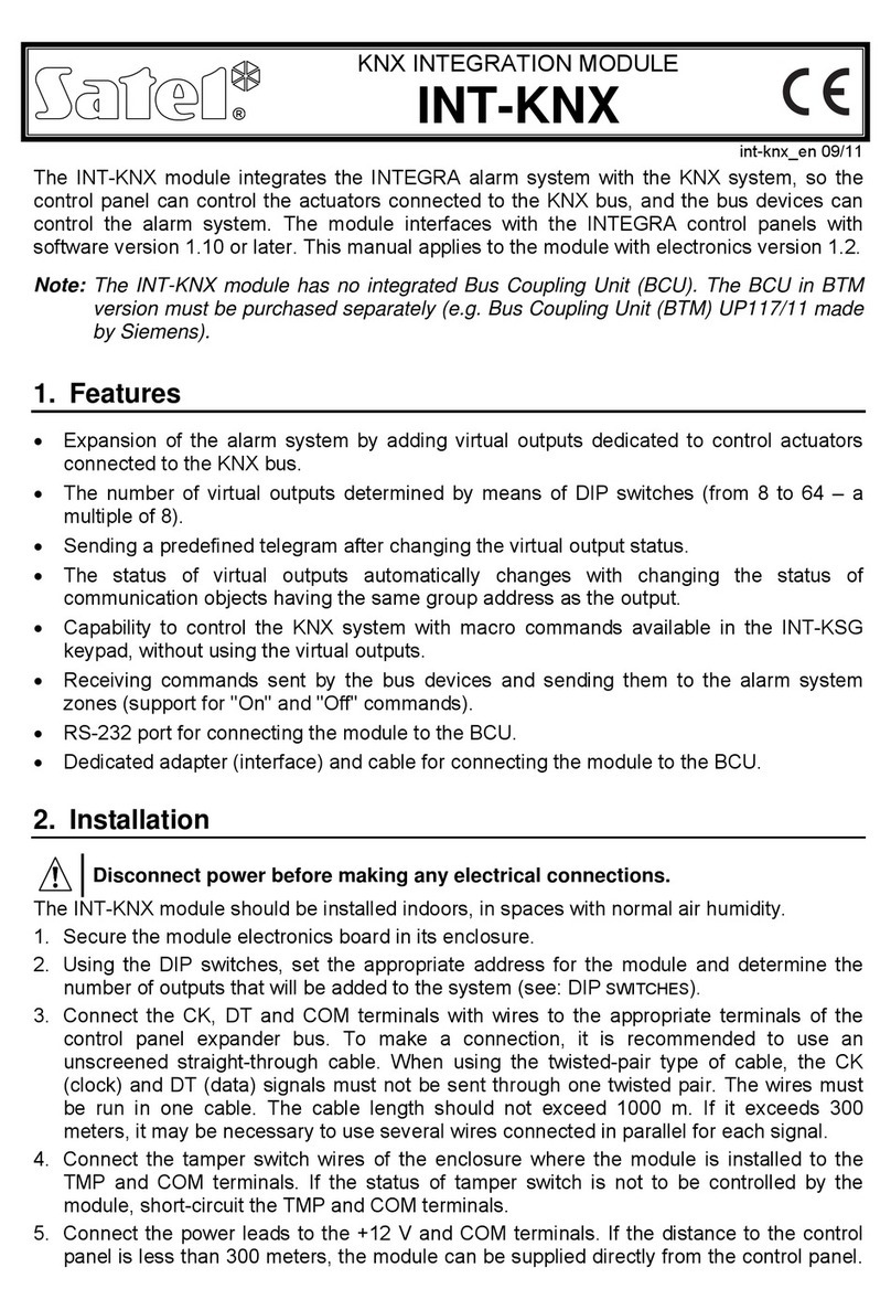
Satel PK-01 User manual

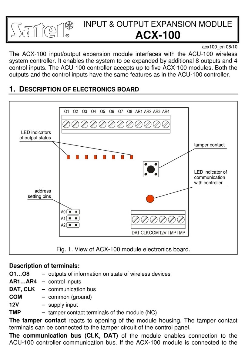
Standalone door control module
PK-01
Firmware version 1.00 pk-01_en 06/12
SATEL sp. z o.o.
ul. Schuberta 79
80-172 Gdańsk
POLAND
tel. + 48 58 320 94 00
www.satel.eu

WARNINGS
Read carefully this manual before proceeding to installation.
Changes, modifications or repairs not authorized by the manufacturer shall void your rights
under the warranty.
SATEL's goal is to continually improve the quality of its products, which may result in
alterations of their technical specifications and firmware. Current information on the
introduced modifications is available on our website.
Please visit us at:
http://www.satel.eu
The declaration of conformity may be consulted at www.satel.eu/ce

SATEL PK-01 1
The PK-01 module is designed for single door control. The access control is effected by
means of electric control of the door status and user identification functions.
1. Features
Support for up to 50 proximity cards (wherever the word "card" is used in this manual, it
means a passive transponder, which may take the form of a proximity card, proximity tag,
etc.), and for 50 codes.
Programming the module and managing the cards and codes by means of the
administrator code.
Ability to block and unblock the door by users with suitable authority level.
Keypad with backlight.
Bell button.
Built-in reader for cards, tags and other 125 kHz passive transponders.
LED indicators of the door and module status.
Built-in piezoelectric transducer for sound signals.
Relay output for control of electromagnetic lock, gate controllers or other devices to
activate the door.
2 OC type outputs:
– indication of alarm status;
– bell signal.
2 dedicated inputs to connect:
– door status sensor;
– request-to-exit button/device.
Enclosure suitable for outdoor installation.
Tamper protection in 2 ways – cover removal and tearing enclosure from the wall.
Powered by 12 V DC (±15%).
2. Description
2.1 LED indicators
red ON – alarm (signaling lasts 10 seconds);
blinking – alarm memory (signaling lasts until a code is entered or
a card is read in by any user).
The alarm can be caused by:
forced entry,
3 attempts to get access using unknown identifier (code or card),
module tamper.
green ON – the door is unblocked (permanently unlocked),
blinking – the door is unlocked (the user has gain access).
yellow ON – the door is blocked (permanently locked).

2 PK-01 SATEL
When the code change and service functions are in use, the LEDs are used for
communication with the user.
2.2 Keys
The number keys and the and keys are used for entering the code and starting the
functions available in the module and for programming the module.
The key (bell button) controls the OC output of the module. Pressing the bell button
activates the output, which remains on as long as the button is held down.
2.3 Wires
Wire color Funcktion
red power supply input (+12 V)
blue common ground (COM)
greek alarm output
black request-to-exit input
yellow NO relay contact (normally isolated from the common relay contact)
pink NC relay contact (normally shorted to the common relay contact)
grey C relay contact (common contact)
brown
door status input (if the door status is not monitored, you will be unable to
unblock / block the door, and the forced entry and long open-door status
will not be signaled)
violet bell output (OC type)
Table 1. Colors and functions of the keypad wires.
3. Installation
Disconnect power before making any electrical connections.
Mounting the module on a metal surface may reduce the working range of the reader, or
even completely disable its operation.
1. Remove the enclosure locking screw and open the enclosure.
2. Secure the enclosure base to the wall.
3. Close the enclosure and replace the enclosure locking screw.
4. Connect individual wires according to Table 1.
4. Users
Users are identified on the basis of their access code or proximity card assigned to them by
the administrator. The access code can consist of 4 to 12 digits.
By default, the administrator (user No. 50) is preprogrammed with the factory code 12345. It
is recommended that you change the code when you first time enter the service mode. The
administrator can use the functions available in the service mode.

SATEL PK-01 3
5. Using the module
5.1 Unlocking the door
5.1.1 Unlocking the door with identifiers
Bring the card close to the module (to a distance allowing the card to be read) or enter the
code and confirm it with the key to start the procedure of user verification. Having
identified the user, the module will signal the door unlocking with a short beep. The relay will
activate for a preset time during which the door opens freely. Depending on the module
settings, the relay operate time after opening / closing the door can be shortened. The door
should be closed before expiry of the maximum door open time.
The door will remain locked if the card or the code is unknown (2 long beeps) or the door is
blocked (2 long beeps and the yellow LED is lit up).
5.1.2 Unlocking the door without user identification procedure
The door can be unlocked using the request-to-exit button/device. Using it will cause the
same response of the module, as in case of the user identification based on the card or code.
5.2 Blocking the door
The door can be blocked (permanently locked) by the user authorized to block / unblock the
door.
Note: The user can only block the door when the door status is being monitored (see the
"Programming the door status input" function).
In order to block the door, do the following:
1. Make sure that the door operates in normal mode and the door is closed.
2. Place the card in proximity of the module and hold it for about 4 seconds or enter the
code and confirm with the key. The device will confirm with 2 short beeps that the door
is blocked. The yellow LED will light up.
5.3 Restoring the door to normal operation mode
The blocked / unblocked door can be restored to its normal operating mode by a user
authorized to block / unblock the door. It can be done using a proximity card or code.
In order to restore the normal operating mode of the door, place the card in close to the
module and hold it for about 4 seconds or enter the code and confirm with the key. The
device will signal restoration of the door to the normal operating mode by 2 short beeps.
5.4 Unblocking the door
The door can be unblocked (permanently unlocked) by the user authorized to block / unblock
the door.
Note: The user can only unblock the door when the door status is being monitored (see the
"Programming the door status input" function).
In order to unblock the door, do the following:
1. Make sure that the door operates in normal mode and open the door.
2. Place the card in proximity of the module and hold it for about 4 seconds or enter the
code and confirm with the key. The device will confirm with 2 short beeps that the door
is unblocked.

4 PK-01 SATEL
5.5 Code change
1. Press the key, and then the key. The module will generate 2 short beeps and the
green and red LEDs will start blinking simultaneously.
2. Enter the code and confirm with the key. The module will generate 2 short beeps.
3. Enter the new code.
Note: If the code entered has already been assigned to another user, the module will
generate 2 long beeps.
4. Confirm the entered code with the key. The module will generate 4 short beeps and 1
long beep, and the two LEDs will go out.
6. Programming the module
Programming is done using the functions available in the service mode.
6.1 Service mode
In order to start the service mode, do the following:
1. Press the key and then the key. The module will generate 2 short beeps, the red
and green LEDs will start blinking simultaneously.
2. Enter the administrator code (by default: 12345) and confirm using the key. The
module will generate 2 short beeps and the red and green LEDs will start blinking
alternately.
3. Press the key corresponding to the function number and confirm with the key. The
module will generate 2 short beeps and the red and green LEDs will be lit continuously.
Note: After 45 seconds of inactivity (in case you do not press any key), the service mode will
be automatically terminated.
6.2 Service mode menu
Shown in square brackets are the key sequences for calling the required submenu or starting
the required function.
[0#] Exit service mode
[1#] Add, remove or edit the user code
[2#] Add or remove user card
[3#] Program user authority level
[0#] basic
[1#] with option to block / unblock door
[4#] Program door status input:
[0#] unused
[1#] NC type
[2#] NO type
[5#] Program request-to-exit input:
[0#] unused
[1#] NC type
[2#] NO type
[6#] Program maximum door open time

SATEL PK-01 5
[7#] Program relay operation time
[8#] Configure relay operation time reducing function:
[0#] disabled
[1#] when door open
[2#] when door closed
[9#] Configure backlighting:
[0#] off
[1#] automatic
[2#] permanent
When navigating through the service mode, keep the following principles in mind:
1. After selecting a function from the main menu (from 1 to 9), the green and red LEDs will
be steadily lit.
2. After saving each change, the module will generate 4 four short beeps and 1 long beep.
The entry of erroneous data is indicated with 2 long beeps. In both cases, after generating
the signal, the device returns to the main menu.
3. To exit the function, without making or confirming any change, press the key.
Exiting the service mode
Press the key and confirm with the key. The module will generate 4 short beeps and 1
long beep.
Adding / editing the user code
Notes:
Adding a new code is equivalent to adding a user.
You can enter up to 49 user codes.
You cannot delete the administrator.
During the process of adding codes, it is recommended that you additionally make a list of
users and numbers assigned to them.
1. Press the key and confirm with the key. The module will generate 2 short beeps.
2. Enter the number of user to whom a code is to be added / whose code is to be changed.
Note: If the yellow LED lights up after entering the user number, it means that the code of a
user with this number is already saved in the module.
3. Confirm with the key. The module will generate 2 short beeps.
4. Enter the code.
Note: If the entered code has already been assigned to another user, the module will
generate 2 long beeps. In such a case the whole procedure of code adding should be
repeated from the beginning.
5. Confirm with the key. The module will generate 4 short beeps and 1 long beep.
Deleting the user code
1. Press the key and confirm with the key. The module will generate 2 short beeps.
2. Enter the number of the user whose code is to be removed.

6 PK-01 SATEL
3. Confirm with the key. The module will generate 2 short beeps. The yellow LED will light
up.
4. Press the key three times.
5. Confirm with the key. The module will generate 4 short beeps and 1 long beep.
Adding the user card
Notes:
Adding a new card is equivalent to adding a user.
You can enter up to 50 user cards.
During the process of assigning cards, it is recommended that you additionally make a list
of users and numbers assigned to them.
1. Press the key and confirm with the key. The module will generate 2 short beeps.
2. Enter the number of user to whom a card is to be added.
Note: If the yellow LED lights up after entering the user number, it means that the card of a
user with this number is already saved in the module.
3. Confirm with the key. The module will generate 2 short beeps.
4. Present the card to the module. After read-in, the module will generate 4 short beeps and
1 long beep.
Note: If the presented card has already been assigned to another user, the module will
generate 2 long beeps. In such a case the whole procedure should be repeated from
the beginning.
Deleting the user card
1. Press the key and confirm with the key. The module will generate 2 short beeps.
2. Enter the number of the user whose card is to be removed.
3. Confirm with the key. The module will generate 2 short beeps. The yellow LED will light
up.
4. Press the key. The module will generate 4 short beeps and 1 long beep.
Programming the user authority level
1. Press the key and confirm with the key. The module will generate 2 short beeps.
2. Enter the number of the user whose authority level is to be defined.
3. Confirm with the key. The module will generate 2 short beeps.
4. If the user is only to have access to the door, press the key.
5. If the user is to have, in addition to the access to the door, the authority to block or unblock
it, press the key.
6. Confirm with the key. The module will generate 4 short beeps and 1 long beep.
Programming the door status input
1. Press the key and confirm with the key. The module will generate 2 short beeps.
2. Depending on how the module is to handle the door status input, press:
the key – input unused,
the key – input supports NC type sensor,

SATEL PK-01 7
the key – input supports NO type sensor.
3. Confirm with the key. The module will generate 4 short beeps and 1 long beep.
Programming the request-to-exit input
The request-to-exit input allows to unlock the door for the preprogrammed relay operating
time.
1. Press the key and confirm with the key. The module will generate 2 short beeps.
2. Depending on how the module is to handle the request-to-exit input, press:
the key – input unused,
the key – input supports NC type button/device,
the key – input supports NO type button/device.
3. Confirm with the key. The module will generate 4 short beeps and 1 long beep.
Programming the maximum door open time
This function allows you to define the time during which the door may remain open after the
relay is turned off. If the door status is supervised and the door remains open longer than the
prescribed time, the module will signal a long open door by means of short beeps generated
with high frequency. The maximum door open time can be programmed for 255 seconds.
The value 0 disables the function.
1. Press the key and confirm with the key. The module will generate 2 short beeps.
2. Program the time, using the number keys.
3. Confirm with the key. The module will generate 4 short beeps and 1 long beep.
Programming the relay operation time
The relay operating time is counted from the moment of gaining access by the user or from
using the request-to-exit button by the user. The time can be programmed within the range
from 1 to 255 seconds.
1. Press the key and confirm with the key. The module will generate 2 short beeps.
2. Program the time, using the number keys.
3. Confirm with the key. The module will generate 4 short beeps and 1 long beep.
Configuring the relay operation time reducing function
1. Press the key and confirm with the key. The module will generate 2 short beeps.
2. Depending on whether the module is to reduce the relay operating time, press:
the key – function disabled,
the key – the relay operation time is to be reduced when the door is open,
the key – the relay operation time is to be reduced when the door is closed.
3. Confirm with the key. The module will generate 4 short beeps and 1 long beep.
Configuring the backlight
1. Press the key and confirm with the key. The module will generate 2 short beeps.
2. Depending on how the module keys are to be illuminated, press:
the key – backlight off,
the key – automatic backlight turned on by using any key or presenting the card,
8 PK-01 SATEL
the key – permanent backlight.
3. Confirm with the key. The module will generate 4 short beeps and 1 long beep.
gs7. Restoring factory settin
1. Turn off the module power supply.
2. Short the ends of the green and black wires.
3. Turn on the power supply. The module will generate 4 short beeps and 1 long beep. The
orresponding terminals.
er supply.
0 s
duction – function disabled
factory settings are restored.
4. Turn off the power supply again.
5. Open the ends of the green and black wires.
6. Connect the wires correctly to the c
7. Turn on the module pow
7.1 Factory settings
Administrator code: 12345
Door status input – unused
Request-to-exit input – unused
Maximum door open time –
Relay operation time – 5 s
Relay operation time re
Backlight – automatic
8. Specifications
Supply voltage ................................................................................................... 12 V DC ±15%
Standby current consumption ........................................................................................105 mA
Maximum current consumption ......................................................................................125 mA
Bell output rating ..............................................................................................................30 mA
Alarm output rating...........................................................................................................30 mA
Reader working frequency ............................................................................................125 kHz
Relay contacts rating (resistive load) ................................................................... 2 A / 24 V DC
Environmental class according to EN50130-5 ........................................................................III
Maximum humidity ..........................................................................................................93±3%
Operating temperature range..................................................................................-25...+55 °C
Enclosure dimensions ................................................................................... 47 x 158 x 24 mm
Weight...............................................................................................................................297 g
Table of contents
Other Satel Control Unit manuals

Satel
Satel ACCO Series User manual

Satel
Satel CA-64 ADR-MOD User manual

Satel
Satel INT-VG User manual

Satel
Satel GPRS-A User manual

Satel
Satel GSM-X User manual

Satel
Satel MZ-1 User manual

Satel
Satel SATEL-TR49 SnapOn Quick setup guide

Satel
Satel GSM LT-1S User manual

Satel
Satel INT-RX User manual

Satel
Satel SATEL-LP8 Quick start guide
Popular Control Unit manuals by other brands

Faderfox
Faderfox NEW MODULE PC12 user manual

SOYO
SOYO SOYO-WM24G02 user manual

Boardcon Embedded Design
Boardcon Embedded Design CM3588S Reference User Manual

Danfoss
Danfoss VF3 DN 200 installation guide

Armstrong
Armstrong 3750 Installation and operating instructions

ADTRAN
ADTRAN 1442442F1 quick start guide