Satel ACCO Series User manual

Access control modules
Firmware version 2.02 acco-kp_en 04/10
SATEL sp. z o.o.
ul. Sc uberta 79
80-172 Gdańsk
POLAND
tel. + 48 58 320 94 00
www.satel.eu

SATEL's goal is to continually improve t e quality of its products, w ic may lead to
alterations in t eir tec nical specifications and firmware. Current information on t e
introduced modifications is available on our website.
Please visit us:
ttp://www.satel.eu

Changes in the ACCO access control system, version 2.02
Controller module New ACCO-KPWG and ACCO-KPWG-PS door controller modules
wit support for Wiegand 26 data transmission format.
Door Door blocking / unblocking capability, according to t e access
sc edule.
New options:
− AUTHORIZATION CONTROL,
− ALARM ON UNAUTHORIZED OPEN.
Users ENTRIES LIMIT option for eac door.
New functions of the ACCO- OFT-LT program, version 2.02
Users Capability to automatically create user groups.
Capability to create a user report.
Presence reports Capability of monitoring t e user presence time.
Presence control A tool for monitoring t e employees' presence on t e premises.

2 SATEL ACCO
CONTENTS
1. General ............................................................................................................................. 4
1.1 Electronics board ....................................................................................................................... 5
1.2 Inputs ......................................................................................................................................... 8
1.3 Outputs ...................................................................................................................................... 8
2. Devices interfacing wit t e module .................................................................................. 9
2.1 ACCO-KLCDR-BG / ACCO-KLCDR-BW keypad ....................................................................... 9
2.2 ACCO-SCR-BG keypad wit proximity card reader ................................................................. 11
2.3 CZ-EMM and CZ-EMM2 proximity card readers ...................................................................... 12
2.4 CZ-EMM3 and CZ-EMM4 proximity card readers .................................................................... 13
3. Access control installation ............................................................................................... 14
3.1 Connecting t e ACCO-KLCDR-BG / ACCO-KLCDR-BW keypad ........................................... 15
3.1.1 Connecting t e LCD keypad to terminals......................................................................................... 16
3.1.2 Connecting t e LCD keypad to RJ socket ....................................................................................... 17
3.1.3 Setting t e LCD keypad address ..................................................................................................... 18
3.2 Connecting t e ACCO-SCR-BG keypad .................................................................................. 18
3.2.1 Setting t e keypad address .............................................................................................................. 19
3.3 Connecting t e proximity card readers .................................................................................... 19
3.4 Connecting activators and sensors of t e controlled door ....................................................... 20
3.5 Sluice ....................................................................................................................................... 20
3.6 Connecting power supply ......................................................................................................... 21
3.6.1 ACCO-KP / ACCO-KPWG module .................................................................................................. 21
3.6.2 ACCO-KP-PS module ...................................................................................................................... 21
4. Addressing t e module ................................................................................................... 22
5. Programming t e module ................................................................................................ 22
5.1 Programming from LCD keypad .............................................................................................. 23
5.1.1 Service mode menu ......................................................................................................................... 23
5.1.2 Data entry ......................................................................................................................................... 24
5.1.3 Programming bit options .................................................................................................................. 25
5.2 ACCO-SOFT-LT program ........................................................................................................ 25
5.2.1 Installation and first start of t e program .......................................................................................... 25
5.3 Module functions and options .................................................................................................. 29
5.4 Functions and options related to t e door ................................................................................ 30
5.4.1 Door unblocking ............................................................................................................................... 31
5.4.2 Door blocking ................................................................................................................................... 31
5.5 Functions and options related to t e LCD keypad ................................................................... 32
5.6 Backlig t settings ..................................................................................................................... 32
5.7 Transmission format ................................................................................................................ 32
6. Users .............................................................................................................................. 32
6.1 Adding new users .................................................................................................................... 33
6.1.1 Adding a new user by means of LCD keypad .................................................................................. 33
6.1.2 Adding new users by means of t e ACCO-SOFT-LT program ........................................................ 33
6.2 Editing users ............................................................................................................................ 36
6.2.1 Editing a user by means of LCD keypad .......................................................................................... 36
6.2.2 Editing a user by means of ACCO-SOFT-LT program .................................................................... 37
6.3 Removing users ....................................................................................................................... 37
6.3.1 Removing a user by means of LCD keypad .................................................................................... 37
6.3.2 Removing a user by means of ACCO-SOFT-LT program ............................................................... 38
6.4 User groups ............................................................................................................................. 38
6.4.1 Creating a user group....................................................................................................................... 38
6.4.2 Automatic assigning of user to a group ............................................................................................ 39
6.4.3 Automatic grouping of users ............................................................................................................ 40
6.4.4 Editing a user group ......................................................................................................................... 40
6.4.5 Removing a user group .................................................................................................................... 40
6.5 User(s) report ........................................................................................................................... 40
6.5.1 Creating a user(s) report .................................................................................................................. 40
6.6 Access sc edules .................................................................................................................... 41
6.6.1 Creating t e access sc edule .......................................................................................................... 42
6.6.2 Creating exceptions .......................................................................................................................... 42
6.7 Presence reports ...................................................................................................................... 44
ACCO SATEL 3
6.7.1 Creating a presence report ............................................................................................................... 44
6.8 Presence control ...................................................................................................................... 46
6.8.1 Creating presence control list............................................................................................................ 47
7. Using t e module ............................................................................................................ 48
7.1 Unlocking t e door ................................................................................................................... 48
7.1.1 Unlocking t e door wit identifiers .................................................................................................... 48
7.1.2 Unlocking t e door wit out user identification procedure ................................................................. 49
7.2 Blocking t e door ...................................................................................................................... 49
7.2.1 Blocking t e door wit t e use of identifiers ...................................................................................... 49
7.2.2 Blocking t e door wit out user identification procedure ................................................................... 50
7.3 Unblocking t e door ................................................................................................................. 50
7.3.1 Unblocking t e door wit t e use of identifiers ................................................................................. 50
7.3.2 Unblocking t e door wit out user identification procedure ............................................................... 51
7.4 Restoring t e door to normal operation mode .......................................................................... 51
7.4.1 Restoring normal operation mode of t e door wit t e use of identifiers ......................................... 51
7.4.2 Restoring normal operation mode of t e door wit out t e user identification procedure ................. 52
7.5 Audible signaling ...................................................................................................................... 52
7.6 Module factory settings ............................................................................................................ 53
8. Specifications ................................................................................................................. 53
8.1 ACCO-KP-PS / ACCO-KPWG-PS module ............................................................................... 53
8.2 ACCO-KP / ACCO-KPWG module ........................................................................................... 54
8.3 ACCO- KLCDR-BG / ACCO-KLCDR-BW keypad .................................................................... 54
8.4 ACCO-SCR-BG keypad wit proximity card reader ................................................................. 54
9. History of c anges to t e manual ................................................................................... 55

4 SATEL ACCO
1. General
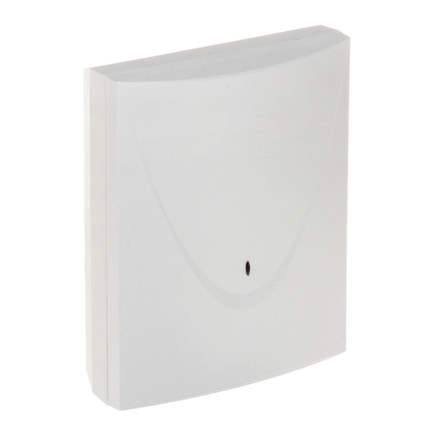
T e SATEL company offers four types of access control modules: ACCO-KP-PS, ACCO-KP,
ACCO-KPWG-PS and ACCO-KPWG. T e door controller module is designed for single door
control. It can operate as a fully autonomous unit or be part of a larger access control system.
T e access control is effected by means of electric control of t e door status and user
identification functions. T e users are identified by t eir proximity card (w erever t e word
"card" is used in t e manual, it means a passive transponder, w ic may ave t e form of a
card, key fob etc.) or access code. T e way of user identification depends on t e type of
identifying devices connected to t e module:
• t e ACCO-KLCDR-BG / ACCO-KLCDR-BW keypad (t e keypads differ by t e color of
t eir ousing: gray in ACCO-KLCDR-BG, w ite in ACCO-KLCDR-BW) or t e
ACCO-SCR-BG keypad – t e user identification and execution of functions available in t e
module are possible, based on t e proximity card or code. T e administrator may define
t e basis on w ic access will be granted to t e users:
− proximity card and code;
− proximity card or code;
− proximity card;
− code.
• t e CZ-EMM, CZ-EMM2, CZ-EMM3 or CZ-EMM4 proximity card reader – t e user
identification and execution of functions available in t e module are only possible, based
on t e proximity card.
A single module makes it possible to register 1024 users, eac of t em being assigned
a unique identification number. T e controller module enables one of 256 weekly access
sc edules to be assigned to eac user. By means of t e ANTI-PASSBACK function, it is
possible to prevent any attempts of repeated entry or exit by using t e same identifier.
T e relay output makes it possible to control electric strike, electromagnetic lock, gate
controller or ot er devices w ic activate t e door. Additional inputs and outputs of t e
module enable it to interface wit a security system, protecting t e facility from burglary or
fire.
T e module is fitted wit a non-volatile memory, w ic enables saving more t an 24
t ousand events. Information related to work time recording can be saved to t e events
log.
LCD keypad or PC computer wit t e ACCO-SOFT-LT program installed s ould be used to
program t e module settings. T e program is delivered free of c arge wit t e device. Apart
from t e single module configuration function, it permits programming settings of a structure
consisting of up to 255 modules. T e program enables convenient operation and facilitates
supervision over t e access control system, offering suc tools as t e site plan, presence
time report or user presence control.
T e module can be connected to t e RS-485 bus, t us making it possible to build a system
including up to 255 modules. Connection of t e RS-485 bus to PC computer and
management of t e access control system from t e computer is possible owing to t e USB /
RS-485 ACCO-U B converter.
T e module firmware is updateable.
T e switc ing mode power supply in t e ACCO-KP-PS / ACCO-KPWG-PS door controller
module is fitted wit a battery c arging and control system, including disc arged battery
disconnect feature.

ACCO SATEL 5
1.1 Electronics board
C NO NCCOM +12V OUT2 OUT1
ITMP +GA SIGA COM BPA LD1A LD2A DISA TMPA +GB SIGB COM BPB LD1B LD2B DISB TMPB
A RS485 B
IN1 IN2 IN3 IN4 IN5 CLK DAT COM
AC AC
1
2345
67
8
9
Fig. 1. Sc ematic view of electronics board in ACCO-KP-PS door controller module.
+GA SIGA COM BPA LD1A LD2A DISA TMPA +GB SIGB COM BPB LD1B LD2B DISB TMPB
A RS485 B
IN1 IN2 IN3 IN4 IN5 CLK DAT COM
C NO NC COM +12V TMP TMP OUT2 OUT1
ITMP
9
2
6
34
5
7
8
Fig. 2. Sc ematic view of electronics board in ACCO-KP door controller module.

6 SATEL ACCO
C NO NCCOM +12V OUT2 OUT1ITMP +G SIG1A
COM BPA LD1A LD2A DISA TMPA SIG2B BPB LD1B LD2B DISB TMPB
A RS485 B
IN1 IN2 IN3 IN4 IN5 CLK DAT COM
AC AC
1
2345
6 7
8
9
SIG2A SIG1B
Fig. 3. Sc ematic view of electronics board of ACCO-KPWG-PS door control module.
+G COM SIG1A SIG2A BPA LD1A LD2A DISA TMPA SIG1B SIG2B BPB LD1B LD2B DISB TMPB
A RS485 B
IN1 IN2 IN3 IN4 IN5 CLK DAT COM
C NO NC COM +12V TMP TMP OUT2 OUT1
ITMP
9
2
6
34
5
7
8
Fig. 4. Sc ematic view of electronics board of ACCO-KPWG door control module.
Explanations for Fig. 1, 2, 3 and 4:
1 – battery connecting leads (ACCO-KP-PS and ACCO-KPWG-PS).
2 – relay.

ACCO SATEL 7
3 – indicator LED of OUT2 output status – lit w en t e output is s orted to common
ground.
4 – indicator LED of OUT1 output status – lit w en t e output is s orted to common
ground.
5 – indicator LED for signaling relay operation.
6 – CR2032 3 V battery for real-time clock back-up.
7 – indicator LED of t e module microprocessor circuit – lig ts wit c anging intensity.
8 – DIP-switch pack for setting an individual address of t e module. Based on t e address,
t e module is identified by t e ACCO-SOFT-LT program.
9 – R -232 port (TTL standard) for computer connection (dedicated cable for making t e
connection is manufactured by SATEL under t e name of DB9FC/RJ). By means of PC
computer wit t e ACCO-SOFT-LT program installed, it is possible to configure t e
device and read t e events.
10 – socket for future applications.
11 – indicator LED of module operation – lit steadily during normal operation; blinking
slowly w en t e LCD keypad connected to t e module is running in t e service mode;
blinking rapidly w en t e ACCO-SOFT-LT program is establis ing communication wit
t e controller.
12 – RJ socket (4p/4c type) dedicated to connecting t e LCD keypad for t e time of
programming.
13 – tamper contact w ic reacts to opening of t e module ousing (ACCO-KP and
ACCO-KPWG).
Description of terminals:
AC – supply input in ACCO-KP-PS and ACCO-KPWG-PS (18 V AC ±10%).
COM – common ground.
+12V – supply output in ACCO-KP-PS and ACCO-KPWG-PS; supply input in
ACCO-KP and ACCO-KPWG (12 V DC ±15%).
C – common terminal of relay output.
NO – contact normally disconnected from t e common terminal of relay output.
W en active, it is connected to t e common terminal.
NC – contact normally connected to t e common terminal of relay output. W en
active, it is disconnected.
TMP – terminals of ACCO-KP and ACCO-KPWG module tamper contact (NC).
T e terminals can be used in two ways:
• connect to t e external tamper circuit (e.g. alarm control panel);
• connect one of t e terminals to tamper circuit input ITMP, and t e ot er
one to common ground COM.
ITMP – input for connecting tamper circuit.
Note: If the tamper contact is not connected to the ITMP terminal, short the terminal to
common ground.
OUT1…OUT2 – module outputs.
IN1…IN5 – module inputs.
A R 485 B – terminals to be connected to RS-485 bus.
CLK, DAT – terminals to be connected to keypad.
T e ot er terminals are used for connecting t e proximity card readers (see section:
CONNECTING PROXIMITY CARD READERS).

8 SATEL ACCO
1.2 Inputs
Provided on t e module electronics board are 5 inputs w ic can be programmed as NO or
NC and serve t e following functions (s own in square brackets are descriptions from LCD
keypad):
Door status control [Door control] – control of t e door status.
Note: The door status control, i.e. connecting a sensor to the input programmed as DOOR
STATUS CONTROL is necessary for correct execution of all the functions of access
control.
Unlock button – unlocks t e door for t e time programmed as ACCESS TIME.
Door unblocking [Unbl. input] – permanently unlocks t e door after control signal appears.
T e door will stay unlocked as long as t e control signal is supplied to t e input (unless
anot er event occurs w ic will ot erwise c ange t e door status).
Door blocking [Blocking inp.] – permanently locks t e door after control signal appears.
T e door will stay locked as long as t e control signal is supplied to t e input (unless
anot er event occurs w ic will ot erwise c ange t e door status).
luice configuration [Sluice config.]– status control of t e second door, forming a sluice.
Only one door can be open in t e sluice configuration.
Fire – unblock door [Fire-unblock.] – permanently unlocks t e door in case of fire. T e door
will stay unlocked until its status is c anged by a user aving t e SWITCHING aut ority.
T e time of supplying t e signal onto t e input as no effect on t e door unblocking
time.
Alarm – block door [Alarm-block.] – permanently locks t e door in case of alarm. T e door
will stay locked until its status is c anged by a user aving t e SWITCHING aut ority. T e
time of supplying t e signal onto t e input as no effect on t e door blocking time.
Bell signal [Bell] – activates t e BELL SIGNAL type of outputs.
Information inputs 1÷4 [Inform. inp. 1÷4] – generates t e pre-defined event. T e function
can be used e.g. to record working time.
It is necessary to determine t e sensitivity for eac input, i.e. t e minimum time span during
w ic t e signal must appear at t e input for t e module to take t e preset action. T is time
can be programmed wit in t e range from 10 ms to 2.55 s.
Switc es, detectors or, for example, alarm or fire protection system can be connected to t e
inputs. In case of t e NO type of inputs, t e control is effected by s orting to common
ground, and in case of t e NC type of inputs – by isolating from common ground.
1.3 Outputs
T e module electronics board includes relay output to activate access devices, suc as door
strikes, magnetic locks, automatic doors or barrier gates, and two OC type outputs. In active
state, t e OC output is s orted to t e common ground (wit inversed polarization: isolated
from t e common ground).
T e OC outputs can be configured as (s own in square brackets are descriptions from LCD
keypad):
Door status – t e output provides information on t e current status of t e door. It is activated
wit opening of t e door and remains active until t e door is closed. T e output
configured as DOOR STATUS cannot perform ot er functions.
Open door – t e output is activated for t e programmed time period after opening t e door.
Bell signal – t e output becomes active for t e programmed time period after signal is
supplied to t e input programmed as BELL SIGNAL. For t e output configured as BELL
SIGNAL, t e OPEN DOOR function can only be additionally activated.

ACCO SATEL 9
Forced entry – t e output becomes active for a programmed time period after unaut orized
opening of t e door (t e door is locked).
Long open door – t e input output becomes active for a programmed time period, if t e door
remains open after expiry of t e DOOR OPEN TIME.
No terminal presence [Lack of term.] – t e output becomes active for a programmed time
period, if no terminal (LCD keypad, keypad or proximity card reader) as been found
during t e test. T e module controls presence of terminals only w en corresponding
options are enabled (PRESENCE cONTROL - TERMINAL A, PRESENCE cONTROL - TERMINAL B).
If t e options are not enabled, t e output will be unable to execute t e NO TERMINAL
PRESENCE function.
5 invalid attempts – t e output becomes active for a programmed time period, after 5
attempts to read an unregistered proximity card or enter an unknown code ave taken
place. The input is activated irrespective of whether the ANTI- CANNER option is
enabled or not.
AC supply failure [AC loss] – t e output becomes active, if t e time programmed as AC
LOSS REPORT DELAY as elapsed since t e AC supply was lost by t e ACCO-KP-PS /
ACCO-KPWG-PS module, and t e supply as not been restored. T e output remains
active until t e AC supply is restored.
Low battery – t e output becomes active, if t e voltage of battery connected to t e
ACCO-KP-PS / ACCO-KPWG-PS module drops below 11 V for a period of time longer
t an 12 minutes (3 battery tests). T e output remains active until t e battery voltage
rises above 11 V for a period of time longer t an 12 minutes (3 battery tests).
Note: For the output to be able to execute the DOOR STATUS, OPEN DOOR, FORCED ENTRY and
LONG OPEN DOOR type of functions, one of the inputs must monitor the door status
DOOR STATUS CONTROL).
In case of t e outputs activated for a programmed time, you must define t e operation time in
seconds or minutes wit in t e range of 1-120 seconds or 1-120 minutes.
A signaling device can be connected to t e outputs, or t ey can be used to control, for
example, a security system.
2. Devices interfacing with the module
For t e module to be able to execute t e access control functions, it is necessary to connect
to it some user identification devices, a device activating t e controlled door (electric strike,
electromagnetic lock, gate controller, turnstile, etc.) and a sensor to monitor t e door status.
As t e user identification devices, t e LCD keypads (ACCO-KLCDR-BG / ACCO-KLCDR-BW),
keypads (ACCO-SCR-BG) or proximity card readers (CZ-EMM, CZ-EMM2, CZ-EMM3
a CZ-EMM4) can be connected.
W en building an access control system, t e ACCO-USB converter must be used. It allows
control of t e modules connected to t e RS-485 bus from a computer. T e ACCO-USB
converter as been described in a separate manual.
2.1 ACCO-KLCDR-BG / ACCO-KLCDR-BW keypad
• Large, legible LCD display.
• Keypad to enter t e access code.
• Built-in proximity card reader.
• Support of cards, key fobs and ot er 125 kHz passive transponders (UNIQUE, EM4001,
EM4002, EM4003, EM4102).

10 SATEL ACCO
• Indicator LEDs of t e door/module status.
• Buzzer generating information beeps after reading t e card / entering t e code (see
section: AUDIBLE SIGNALING) and signaling operations performed on t e keypad.
• Backlig ting of t e display and keys.
• Tamper contact reacting to opening of t e ousing.
Fig. 5. View of t e ACCO-KLCDR-BG keypad (t e ousing of ACCO-KLCDR-BW keypad is
w ite).
Designation of indicator LEDs:
ALARM (red color) – t e LED is lit, signaling alarm, w en one of t e following situations
as occurred:
− door opened by force,
− 5 attempts to get access on t e basis of an unknown identifier (Anti-scanner
function),
− FIRE – UNBLOCK DOOR input activated,
− ALARM – BLOCK DOOR input activated,
− tamper of t e door controller module (t e ITMP input of module controller is
isolated from t e common ground),
− tamper of keypad,
− loss of communication wit t e terminal unit (no terminal presence).
T e alarm is signaled for 10 seconds (and accompanied by audible signal). W en t at
time expires, t e LED starts blinking, t us signaling alarm memory. After t e alarm
cause as ceased, t e alarm memory signal can be reset by t e user aving t e

ACCO SATEL 11
ADMINISTRATOR aut ority. T is will be done automatically after e uses is identifier.
T e alarm memory will also be automatically cleared w en t e alarm cause as
ceased to exist, if t e controller module is connected to t e computer (by means of
t e RS-232 or RS-485 port) and t e ACCO-SOFT-LT program.
DOOR BLOCKED (yellow color)
– LED is lit – t e door is blocked (permanently locked) and it cannot be unlock by
presenting card / entering code,
– LED is blinking– t e door as been blocked (permanently locked) by means of t e
input programmed as ALARM – BLOCK DOOR (presenting card / entering code will
not unlock t e door).
DOOR UNBLOCKED (green color)
– LED is lit – t e door is unblocked (permanently unlocked) and presenting card /
entering code is not required,
– LED is blinking slowly – t e door as been unblocked (permanently unlocked) by
means of t e input programmed as FIRE – UNBLOCK DOOR (presenting card /
entering code is not required),
– LED is blinking rapidly – t e user as been granted access, t e door as been
unlocked and t e access time countdown is running, i.e. it is possible to open t e
door.
ERVICE (green color) – t e LED is blinking w en t e module is in t e service mode
(t e function is available to t e users wit ADMINISTRATOR aut ority level).
2.2 ACCO- CR-BG keypad with proximity card reader
• T e keypad enables entering t e code.
• Support of cards, key fobs and ot er 125 kHz passive transponders (UNIQUE, EM4001,
EM4002, EM4003, EM4102).
• Indicator LEDs of t e door / module status.
• Buzzer generating information beeps after reading t e card / entering t e code (see
section: AUDIBLE SIGNALING) and signaling operations performed on t e keypad.
• Backlig ting of t e keys.
• Tamper contact reacting t e ousing opening/pull-off.
• Bell button.
• Design enabling outdoor installation.
Information conveyed by t e keypad t roug t e indicator LEDs , and is identical to
t at in case of t e LCD keypad.

12 SATEL ACCO
Fig. 6. View of t e ACCO-SCR-BG keypad.
2.3 CZ-EMM and CZ-EMM2 proximity card readers
• Support of cards, key fobs and ot er 125 kHz passive transponders (UNIQUE, EM4001,
EM4002, EM4003, EM4102).
• Transmission format: EM-MARIN.
• Two-color indicator LED of t e door/reader status.
• Buzzer generating information beeps after reading t e card (see section: AUDIBLE
SIGNALING).

ACCO SATEL 13
T e two-color indicator LED in t e reader can signal as follows:
steady green light – normal operation of t e reader.
blinking green rapidly – access as been granted to t e user, t e door as been unlocked
and t e access time countdown is running, so it is possible to open t e door.
blinking green slowly – t e door is unblocked (permanently unlocked).
blinking red slowly – t e door is blocked (permanently locked).
red light, periodically extinguished – t e reader as been blocked after 5 attempts to get
access by using an unknown identifier (ANTI-SCANNER is activated).
steady red light – t e reader cannot be controlled by t e module (LCD keypad as been
connected, w ic as disabled operation of t e reader).
2.4 CZ-EMM3 and CZ-EMM4 proximity card readers
• Support of cards, key fobs and ot er 125 kHz passive transponders (UNIQUE, EM4001,
EM4002, EM4003, EM4102).
• Transmission format: EM-MARIN or WIEGAND 26.
• Two indicator LEDs of t e door/reader status.
• Buzzer generating information beeps after reading t e card (see section: AUDIBLE
SIGNALING).
• Design enabling outdoor installation.
• Bell button in t e CZ-EMM4 reader.
T e green LED in t e reader signals as follows:
lit – normal operation of t e reader.
blinking rapidly – access as been granted to t e user, t e door as been unlocked and t e
access time countdown is running, so it is possible to open t e door.
blinking slowly – t e door is unblocked (permanently unlocked).
T e red LED in t e reader signals as follows:
lit – t e reader cannot be controlled by t e module (LCD keypad as been connected, w ic
as disabled operation of t e reader).
blinking slowly – t e door is blocked (permanently locked).
Fig. 8. CZ-EMM2 reader.
Fig. 7. CZ-EMM reader.

14 SATEL ACCO
lit, but periodically extinguished – t e reader as been blocked after 5 attempts to get
access by using an unknown identifier (ANTI-SCANNER is activated).
3. Access control installation
Disconnect power supply before making any electrical connections.
T e door controller module s ould be installed indoors, in spaces wit normal air umidity.
T e controller module installation place s ould be protected against access of unaut orized
persons. It is recommended t at t e controller module be installed wit in t e area w ic is
protected (e.g. by security system).
T e distance between t e terminal units s ould be not less t an 50 cm.
Mounting t e terminals (keypads wit proximity card reader, readers) on metal surface or in
metal ousing may result in reduction of t e reader range or even make t e proximity card
readout entirely impossible.
For connection of t e terminals, activators (electric strike, electromagnetic lock) and sensors
of t e controlled door, it is recommended t at straig t-t roug unscreened cable be used
(using t e "twisted-pair" type of cable, e.g. UTP, STP, FTP, is not recommendable). Select
t e cross-section area of t e power leads so t at t e supply voltage drop between t e power
supply unit and t e supplied device not exceed 1 V as compared wit t e output voltage.
W en connecting a proximity card reader or LCD keypad as t e terminal A, you s ould
remember t at it will be recognized as t e entry terminal. A proximity card reader or LCD
keypad working as t e terminal B will be recognized as t e exit terminal.
Fig. 9. CZ-EMM3 reader. Fig. 10. CZ-EMM4 reader.

ACCO SATEL 15
1
2
3
4
5
Fig. 11. An example of access control installation.
Explanations for Fig. 11:
1 – door controller module.
2 – controlled door activator (electromagnetic lock controlled from t e module relay
output).
3 – controlled door sensor (magnetic detector connected to t e module input
programmed as DOOR STATUS CONTROL).
4 – exit terminal (proximity card reader connected as reader B).
5 – entry terminal (proximity card reader connected as reader A).
3.1 Connecting the ACCO-KLCDR-BG / ACCO-KLCDR-BW keypad
T e LCD keypad can be connected to t e module by means of t e terminals on electronics
board or t e RJ socket. Use four-core cable for making t e connection. T e distance
between t e keypad and t e module can be up to 300m.
The module supports keypads with addresses 0 and 1. The keypad with address 0 will
serve as terminal A (entry terminal). The keypad with address 1 will serve as terminal B

16 SATEL ACCO
(exit terminal). The information whether the keypad performs the function of terminal A
or B can be read out from the display after restarting the keypad (in order to cause the
restart, hold down the
and
keys for approximately 10 seconds).
Notes:
• Connecting the LCD keypad with address 0 will switch off the proximity card reader
working as reader A. Connecting the LCD keypad with address 1 will switch off the
proximity card reader working as reader B.
• Never connect two devices LCD keypads, keypads) which have an identical address.
If t e clock and additional information fail to appear on t e keypad display after power-up,
make sure t at:
− t e cables connecting t e keypad to t e module ave been properly connected;
− a correct address is set in t e keypad.
3.1.1 Connecting the LCD keypad to terminals
T e met od of connecting t e keypad communication bus to t e terminals of ACCO-KP and
ACCO-KP-PS modules is s own on Fig. 12 and Fig. 13.
+GA SIGA COM BPA LD1A LD2A DISA TMPA +GB SIGB COM BPB LD1B LD2B DISB TMPB
A RS485 B
IN1 IN2 IN3 IN4 IN5 CLK DAT COM
C NO NC COM +12V TMP TMP OUT2 OUT1
ITMP
ACCO-KP
COM
KPD
CKM
DTM
ACCO-KLCDR-BG
Fig. 12. Met od of connecting t e keypad to ACCO-KP module terminals.

ACCO SATEL 17
C NO NCCOM +12V OUT2 OUT1
ITMP +GA SIGA COM BPA LD1A LD2A DISA TMPA +GB SIGB COM BPB LD1B LD2B DISB TMPB
A RS485 B
IN1 IN2 IN3 IN4 IN5 CLK DAT COM
AC AC
ACCO-KP-PS
COM
CKM
DTM
ACCO-KLCDR-BG
Fig. 13. Met od of connecting t e keypad to ACCO-KP-PS module terminals.
3.1.2 Connecting the LCD keypad to RJ socket
T e met od of connecting t e LCD keypad communication bus to t e RJ socket is s own on
Fig. 14. T e socket is dedicated to connecting t e LCD keypad for t e duration of
programming w enever devices connected to t e module do not offer t e possibility of its
programming.
1 - +KPD
2 -
3 -
4 - COM
CKM
DTM
1 2 34
1 2 34
Fig. 14. Sequence of wires in t e plug connecting LCD keypad wit module. 1 – view of
plug in socket. 2 – view of plug from pins side.
In order to program t e module, you can use any LCD keypad supported by t e INTEGRA
control panels. However, suc a keypad is not recommended for everyday operation of t e
module because of different LED designations. T e module can andle t e readers in
INT-KLCDR-GR and INT-KLCDR-BL LCD keypads wit firmware version 1.06 or later.

18 SATEL ACCO
Note:
• If one ACCO-SCR-BG keypad and any proximity card reader is connected to the controller
module, the address set in LCD keypad must be different from that set in the keypad:
1 – if address 0 is set in the keypad,
0 – if address 1 is set in the keypad.
• If 2 ACCO-SCR-BG keypads are connected to the controller module, you must disconnect
one of them from the DAT terminal green wire), and set in the LCD keypad the identical
address, as in the disconnected keypad.
3.1.3 etting the LCD keypad address
1. Disconnect t e keypad supply (KPD) and t e data bus cables (CKM, DTM).
2. S ort toget er t e keypad terminals CKM and DTM.
3. Connect t e keypad supply.
4. Keypad address will be displayed:
Fig. 15. Programming LCD keypad address.
5. C ange t e address to t e correct one (0 or 1). T e keypad will acknowledge t e address
setting by 4 s ort beeps and 1 long beep.
6. Disconnect t e keypad supply (KPD).
7. Connect t e keypad to t e door controller module in t e correct way (CKM, DTM
and KPD).
3.2 Connecting the ACCO- CR-BG keypad
T e keypad s ould be connected in accordance wit Table 1. T e connection is to be made
wit five-core cable. T e distance between keypad and module can be up to 300 m.
The module supports keypads with addresses 0 and 1. The keypad with address 0 will
function as terminal A (entry terminal). The keypad with address 1 will function as
terminal B (exit terminal).
Notes:
• Connecting the keypad with address 0 will switch off the proximity card reader working as
reader A. Connecting the keypad with address 1 will switch off the proximity card reader
working as reader B.
• Never connect two devices LCD keypads, keypads) which have an identical address.
Wire color Function Module terminals
brown power supply +12V
w ite common ground COM
gray clock CLK
green data DAT
yellow bell IN1…IN5
(c osen module input, programmed as BELL SIGNAL)
Table 1. Met od of connecting keypad wires to module terminals.
T e yellow wire is connected to t e OC low-current output, controlled by means of t e bell
button. Press t e button to s ort t e output to common ground. T e yellow wire (bell) can be
connected to t e module input programmed as BELL SIGNAL.
n=0...7, currently set
keypad address
This manual suits for next models
5
Table of contents
Other Satel Control Unit manuals

Satel
Satel INT-VG User manual

Satel
Satel ETHM-2 User manual

Satel
Satel INT-GSM User manual

Satel
Satel KNX-BIN24 User manual

Satel
Satel GSM LT-2 User manual

Satel
Satel SATEL-TR49 SnapOn Quick setup guide

Satel
Satel GPRS-A User manual

Satel
Satel ETHM-1 User manual

Satel
Satel INT-KNX-2 User manual

Satel
Satel ACX-100 User manual

Satel
Satel ETHM-1 Plus User manual

Satel
Satel MICRA User manual

Satel
Satel CA-64 PTSA User manual

Satel
Satel GSM LT-1 User manual

Satel
Satel GSM-X User manual

Satel
Satel SATEL-LP8 Quick start guide

Satel
Satel MZ-1 User manual

Satel
Satel INT-VMG User manual

Satel
Satel ETHM-1 Plus User manual

Satel
Satel GSM-4 User manual