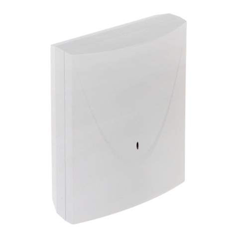
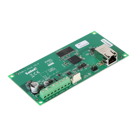
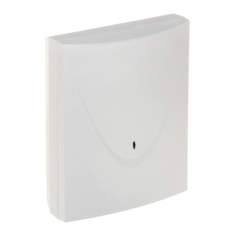
Satel ETHM-2 User manual

Ethernet Module
ETHM-2
Firmware version 2.00 ethm2_en 05/15
FreeRTOS is used in this product (www.freertos.org).
SATEL sp. z o.o.
ul. Budowlanych 66
80-298 Gdańsk
POLAND
tel. + 48 58 320 94 00
www.satel.pl

SATEL's goal is to continually improve the quality of its products, which may result in
alteration of their technical specifications and firmware. Current information on the introduced
modifications is available on our website.
Please visit us at:
http://www.satel.eu

SATEL ETHM-2 1
The ETHM-2 Ethernet module is a dedicated device for use in intruder alarm systems for
reporting purposes. It enables sending event codes via the Ethernet network (TCP/IP) to the
STAM-2 monitoring station or SMET-256 converter. The module can interface with any alarm
control panel (even if is not provided with telephone dialer). It converts codes received in
telephone transmission format or SIA format and generates codes if there are any input
violations, output activations, etc. In the event of codes generated by the module, information
on the event can also be sent by e-mail messages.
The module firmware can be replaced by means of the Ethm-2 Flash program, available on
www.satel.eu website. Remember to save the module settings into the configuration file
before updating the firmware.
1. F
EATURES OF
ETHM-2
ETHERNET MODULE
Simulation of analog telephone line.
Capability to receive monitoring events sent in telephone transmission format (Ademco
Slow, Silent Knight fast, Radionics 1400, Radionics 1400 with parity, Ademco Express
or Contact ID) or SIA format and report them to the monitoring station through Ethernet
with the use of TCP/IP protocols.
Acknowledgment of event receipt.
Buffer for 512 received events.
Coded event transmission.
8 inputs.
4 outputs.
Remote control of output status.
Power supply output.
Monitoring of the status of inputs, outputs, power supply, communications, etc. by means
of codes sent through Ethernet network to 2 monitoring stations and/or by means of e-mail
messages.
Support for encrypted communication with the outgoing mail server.
Module configuration by means of the ETHM-2 Soft program through the RS-232 port or
Ethernet.
Encrypted communication over Ethernet network.
Control of Ethernet cable availability.
Module firmware updating capability.
Built-in switching power supply 1.2 A.
Battery charging and control system.
Power supplied with 16 V AC (±10%) or 12 V DC (±15%).
2. D
ESCRIPTION OF ELECTRONICS BOARD
Terminals description:
AC – power supply input (16 V AC ±10%).
COM – common ground.
+12V – power supply output (if supplied with alternating voltage) or power supply
input (12 V DC ±15%).
OUT1…OUT4 – OC type low-current outputs with current-carrying capacity up to 50 mA.
If active, they are shorted to ground. The outputs can be used for control
of low power consumption devices (e.g. indicator LEDs, sirens with own

2 ETHM-2 SATEL
power supply) or relays (by using relays, it is possible to control high
power devices).
Z1…Z8 – inputs. For example, alarm control panel outputs can be connected to the
inputs (with the control panel and ETHM-2 module suitably programmed,
this will enable monitoring the status of control panel which is not fitted
with telephone dialer).
TIP, RING – terminals for connecting the control panel telephone dialer.
Note: Do not connect the telephone exchange or any devices simulating the analog
telephone line to the TIP and RING terminals.
Fig. 1. View of the module electronics board.
Explanations for the figure:
1 – battery connecting leads (connect the battery only when the module is to be supplied
with 16 V (±10%) alternating voltage).
2 – LED whose blinking indicates the module status:
– lights up for a short while – the device operation is normal
– blinking regularly at a slow rate – configuration data memory error
– blinking regularly at a fast rate – module firmware update running
3 – CR2032 3 V battery for backup of the real time clock.
4 – RJ-45 socket for connecting the module to Ethernet network. 100Base-TX standard
compatible cable should be used. The socket has two built-in LEDs. The green one
indicates connection to the network and data transmission, and the yellow one
- negotiated transmission rate (ON: 100Mb; OFF: 10Mb).
5 – RS-232 port which enables the module to be connected to the computer serial COM
port. The dedicated cable for making this connection, designated DB9F/RJ, is
manufactured by SATEL. Using a computer with the ETHM-2 Soft program installed,
you can configure the device and read the events.

SATEL ETHM-2 3
3. I
NSTALLATION
Disconnect power supply before making any electrical connections.
The ETHM-2 module is designed for indoor installation, in spaces with normal humidity of air.
The module can be supplied with alternating or direct voltage.
3.1 CONNECTION OF ALTERNATING VOLTAGE
If the module is to be supplied with 16 V AC (±10%), it is recommended that a 20 VA
transformer be used. The transformer should be permanently connected to the 230 V AC
mains power supply. Therefore, prior to making any cable connections, familiarize yourself
with the site electrical installation. The circuit to be chosen as power supply circuit is to be
alive at all times and provided with suitable protection.
Never connect two devices with power supply unit to one transformer.
Before cutting in the transformer to the circuit from which it will be power
supplied, deenergize the circuit.
Because the ETHM-2 module has no switch to disconnect the mains power
supply, it is important that you advise the owner / user of the equipment on how
it should be disconnected from the mains (e.g. by indicating the fuse which
protects the power circuit of the module).
Use a 12 V/7 Ah battery as an emergency power supply source for the module.
1. Connect AC voltage from the transformer secondary winding to the module AC terminals.
2. Switch on 230 V AC power supply in the circuit to which the transformer is connected.
Measure the voltage across the battery leads (the correct value should be between 13.6
and 13.8 V DC).
3. Switch off 230 V AC power supply.
4. Connect the battery. The module will not start on connecting the battery alone.
5. Switch on 230 V AC power supply. The module is now ready for operation.
Notes:
A battery voltage drop below 11 V for longer than 12 minutes (3 battery tests) is
recognized as battery discharge. The further voltage drop to approx. 9.5 V will disconnect
the battery.
Additionally, if the module is supplied with AC voltage and the control panel dialer is
connected to the TIP and RING terminals, the COM terminals in panel and module must
be shorted. Thus will prevent the situation when simulating telephone line trouble by the
module fails to be correctly recognized by the control panel.
3.2 CONNECTION OF DIRECT VOLTAGE
If the module is to be supplied with 12 V DC (±15%), the power supply can be provided e.g.
from the alarm control panel, which is to be monitored by means of the module. The power
supply and common ground cables should be connected to the corresponding module
terminals (+12V and COM). Turn on power supply to make the module ready for operation.
4. M
ODULE CONFIGURATION
Note: The device is only designed for working in the local computer networks (LAN).
It cannot be directly connected to the public computer network (MAN, WAN).
Connection to the public network should be established by using an xDSL router or
modem.

4 ETHM-2 SATEL
There are 2 available methods of the module configuration by means of the ETHM-2 Soft
program:
1. Via Ethernet network. Data transmission in the network is encrypted by means of an
advanced algorithm, based on 192-bit key.
2. Through the RS-232 port.
In both cases you must install on your computer the Java Virtual Machine, the installation file
for which should be downloaded from the Internet, whereas the installation file for ETHM-2
Soft program is available for downloading from the www.satel.eu website.
4.1 VIA THE ETHERNET NETWORK
1. Start the ETHM-2 Soft program.
2. In the “Program settings” tab, select the “TCP/IP”, enter the IP address of the module and
the number of the port through which communication is to be effected (see section
C
ONNECTION
p. 7) and click on the “Apply” button. Close and restart the program.
3. The login window will be displayed. Enter in the fields:
the user name (by default: “service” - see section L
OGGING DETAIL
p. 6),
the password (by default: “service” - see section L
OGGING DETAIL
p. 6).
4. Click on the “Login” button. The data from the module will be downloaded automatically.
5. Configure the module settings as required.
6. Save the data to the module.
4.2 VIA THE RS-232 PORT
Fig. 2. Connection of the module to computer serial port. RJ plug is shown on the left. DB-9
female plug, seen from the solder side, is shown on the right.
1. Connect the module RS-232 port (RJ type socket) to the computer COM serial port.
The method of connection is shown in Figure 2(you can buy a ready-made cable,
manufactured by SATEL).
2. Start the ETHM-2 Soft program.
3. In the “Program settings” tab, select the “RS port” and click on the “Apply” button. Close
and restart the program.
4. Select in the program window the computer COM port to which the module is connected.

SATEL ETHM-2 5
5. Click on the symbol to initiate communication with the module.
6. The login window will be displayed. Enter in the fields:
the user name (by default: “service” - see section L
OGGING DETAIL
p. 6),
the password (by default: “service” - see section L
OGGING DETAIL
p. 6).
7. Click on the “Login” button. The data from the module will be downloaded automatically.
8. Configure the module settings as required.
9. Save the data to the module.
4.3 MAIN MENU
Fig. 3. Fragment of the program window with menu.
Explanations for Fig. 3:
1 - button enabling the configuration data to be loaded from file.
2 - button enabling the configuration data to be written to file.
3 - button enabling the data to be read from the module.
4 - button enabling the data to be written to the module.
5 - icon indicating the status of communication with the module (green color – the
program is connected to the module; gray color – no connection with the module).
6 - field enabling selection of the computer COM port, through which communication with
the module will be effected.
7 - button enabling communication with the module to be switched on/off.
8 - information on the progress of writing/reading data.
9 - icon indicating troubles (grayed if there is no trouble).
10 - time by the module clock.
11 - IP address of the module.
12 - MAC number of the module.
13 - module firmware version.
14 - information on outputs. Placed in the upper line are icons indicating the status of
outputs:
- output inactive;
- output active;
Placed in the lower line are icons related to the function of outputs:
- the output is signaling trouble and cannot be controlled;
- the output can be controlled by means of inputs or program. Click on 0 to
disable the output; click on 1 to enable it (for the time programmed in the
I
NPUTS
/O
UTPUTS
tab).

6 ETHM-2 SATEL
15 - information on the status of inputs:
- input status OK;
- input bypassed;
- input violated.
16 - status of simulated telephone line:
- module ready for answering telephone calls;
- module is answering a telephone call;
- module is simulating telephone line trouble (e.g. Ethernet not available).
4.4 “COMMON”TAB
Fig. 4 “Common” tab.
4.4.1 Network
Dynamic IP address – select this option, if the data regarding IP address, subnet mask and
gateway are to be automatically downloaded from DHCP server.
Static IP address – select this option, if the data regarding IP address, subnet mask and
gateway will be entered manually.
IP address – IP address of the module.
Subnet mask – mask of the subnet in which the module operates.
Default gateway – net gateway i.e. IP address of the network device through which the
other devices in the given local network communicate with devices in other networks.
Obtain DNS server address automatically – select this option if the DNS server network
address is to be automatically obtained from DHCP server.
Use the DNS server address – select this option if the preferred DNS server data will be
entered manually.
Preferred DNS server – preferred DNS server address for the module.
4.4.2 Logging detail
User – user name. Required during the procedure of logging into the module. The device can
recognize two users:
user with limited right of access to the device (only allowed to view the event log and
control the inputs). Factory default: satel.
user with full right of access. Factory default: service.

SATEL ETHM-2 7
Password – user password. Required during the procedure of logging into the module.
Factory default:
for “satel” user: satel.
for “service” user: service.
JAVA port – enter in this field the number of TCP port which will be used for communication
with the ETHM-2 Soft program via the Ethernet network. You can enter any value from 1 to
65535. The value must be different from that entered for the other ports. Default value:
33333.
4.4.3 Clock
Summer/winter time – the module can automatically correct the clock settings due to
a change from summer time to winter time and conversely. You can choose from the
following correction patterns:
no correction
by the European Union rules
by the United States rules
1 hour correction according to dates
2 hours correction according to dates
Summer time since – the field is available when the module clock settings are to be
corrected by 1 or 2 hours according to dates. You can enter the date (day, month) when
the module clock will be changed to summer time (i.e. shifted forward).
Winter time since – the field is available when the module clock settings are to be corrected
by 1 or 2 hours according to dates. You can enter the date (day, month) when the module
clock will be changed to winter time (i.e. shifted back).
Time zone – enter in this field the time zone, i.e. the difference between the universal time
(UTC) and the zone time.
Time synchronization – if this box is selected, the module will automatically synchronize its
clock with the time server once a day and just after a restart. In the event of failure, the
module will be repeating the clock synchronization attempt every minute.
Time server (NTP) – enter in this field the IP address of the time server supporting the NTP
protocol.
System time – this field displays the computer clock based time.
Send – when you click on the button, the time displayed in the “System time” field will be
saved to the module.
4.4.4 Default settings restoration
Configuration – select the box and click on the “Restore values” button to reset all the
module settings to their factory default values.
Event log – select the box and click on the “Restore values” button to delete the event log,
i.e. all events, the reception of which was acknowledged by the module, but which have
not been sent yet to the monitoring station.
Note: The procedure of restoring factory settings/deleting event log is followed by restart of
the device.
4.5 “PROGRAM SETTINGS”TAB
4.5.1 Connection
RS port – if this option is enabled, communication will be effected through the RS-232 port.
The option is enabled by default.

8 ETHM-2 SATEL
TCP/IP – if this option is enabled, communication will be effected through the TCP/IP
network.
Address – IP address of the module with which communication is to be established.
Port – number of the port through which communication with the module is to be effected.
Notes:
If the mode of communication has been changed, the program must be restarted.
The IP address defined in the “Program settings” tab may be different from the module IP
address programmed in the “Common” tab, “Network” part. It depends on whether the
communication is effected by means of an address changing network device (such as
router), e.g. in case of communication through the public network (WAN).
Fig. 5. “Program settings” tab.
4.5.2 Language selection
Click on the button to select the program language.
4.6 “REPORTING”TAB
4.6.1 Station 1 / Station 2
Active – select the box if the events are to be sent to the chosen monitoring station.
4.6.1.1 “Common” tab
Reporting format
Selection of the reporting format only applies to the event codes generated by the module
(input monitoring, troubles, etc.). The events received through telephone line are sent to
the monitoring station in the same format in which they were received.
Normal – select this option if the module generated events are to be sent in 4/2 format.
Contact ID – select this option if the module generated events are to be sent in Contact ID
format.
SIA – select this box, if the events generated by the module are to be sent in SIA format.
Active inputs/outputs
If the box at chosen input/output is selected, the status of the input/output will be
monitored. Input violation/end of violation or output activation/deactivation will result in
sending an event code. The codes are defined in the “Event codes” tab.

SATEL ETHM-2 9
Fig. 6. Event codes in Contact ID format, “Reporting” tab.
Monitoring station settings
Server address – network address of the monitoring station.
Port – enter in this field the number of TCP port through which communication with the
monitoring station will be effected. You can enter any value from 1 to 65535. By default:
12345.
Encryption key – enter in this field a sequence of 1 to 12 alphanumeric characters (digits,
letters and special characters) to define the key for coding of the data to be sent to the
monitoring station.
System identifier – enter in this field a sequence of 4 characters for identification of the
device. You can enter digits from 0 to 9 and letters from A to F. Using the digit 0 is not
recommended. Factory default: 0000 (this string is equivalent to the lack of identifier).
Together with the identifier, the codes of module generated events will be sent (inputs
monitoring, troubles, etc.).
SIA prefix – select this box to activate the field for entering 2 characters which will
precede the “System identifier” in case of the SIA format. Thus you can obtain an
identifier consisting of 6 characters. 2 hexadecimal characters (digits or letters from A to
F) should be programmed. If you enter 00, no prefix will be added. Using the digit 0 in
the prefix is not recommended. The option is available if the SIA format is selected.
ETHM key – enter in this field a sequence of 1 to 5 alphanumeric characters for
identification of the Ethernet module.
Note: The data entered in the fields “Port”, “Encryption key”, “System identifier”
and “ETHM key” must be consistent with the corresponding settings defined in the
monitoring station.
Telephone line
Tel. number – enter in this field the telephone number defined in the control panel for
a given monitoring station. Based on the telephone number, the module will determine,
whether to receive the event and to which monitoring station send it. If the field is blank

10 ETHM-2 SATEL
or the entered telephone number is not consistent with that programmed in the control
panel, the module will not be receiving events sent by the control panel.
Extended kiss-off – some control panels require long acknowledgement of receiving the
code in Contact ID format. By default, to speed up communication, a short kiss-off
signal is used in the module. The option is available after selecting the Contact ID
format.
4.6.1.2 “Monitored events” tab
If the box at chosen event is selected, occurrence of the event (and, in case of troubles,
also the end of trouble) will result in sending codes defined in the “Event codes” tab to the
monitoring station. The following events can be monitored:
Internal events:
– Module restart
– Power supply failure (the trouble is reported with a delay, as defined in the
“Inputs/Outputs” tab)
– Power supply restore
– Low battery
– Battery OK
– Loss of communication with Station 1
– Restore of communication with Station 1
– Loss of communication with Station 2
– Restore of communication with Station 2
– Test transmission (this event requires defining test transmission rules)
– Supply output overload
– End of supply output overload
Inputs restore:
– Inputs 1 – 8.
Outputs turning off
– Outputs 1 – 4.
4.6.1.3 “Event codes” tab
The tab makes it possible to define codes for the module generated events.
For the 4/2 format, all codes can be defined. For the Contact ID format and SIA, the codes
are factory defined.
Contact ID
The user can change the codes of events generated after violation of the module inputs
and after activation of the outputs. Defining the code to be sent on input violation/output
activation will automatically generate a code which will be sent at the input end of
violation/output deactivation. You can enter the new Contact ID code manually or use the
code editor. To open the code editor window, click on the button marked with three dots.
SIA
The user can change the codes of events generated on input violation / end of violation
and output activating / deactivating. You can also add a comment to all the generated
events, including the system ones, which will be send with an appropriate code
immediately on sending the main event. You can enter the new SIA code manually or you
can make use of the code editor. To open the code editor window, click on the button
designated with three dots.

SATEL ETHM-2 11
Fig. 7. Event codes in SIA format, “Reporting” tab.
4.6.2 Test transmissions
The “Test transmission” event can be generated:
On time – every specified number of days at defined time. The first event will be generated
at defined time on the same day when test transmission rules are saved to the module, or
on the following day (if defined time on that particular day has already passed). Entering 0
in the “Days” field means that the event will be generated every 31 days.
After time – after a lapse of specified time (days, hours and minutes) from the last event
(irrespective of whether it was a test transmission, or another event was sent). The first
test transmission will be generated approx. 10 seconds after test transmission rules are
saved to the module. Entering 0 in the fields “Days” and “Hours” means that no event will
be generated.
Note: The “Test transmission” event is generated irrespective of whether it is to be sent to
the monitoring station or not. Disabling the feature of generating this type of events is
only possible in the “After time” transmission.
4.7 “INPUTS/OUTPUTS”TAB
4.7.1 Inputs
The following parameters can be defined for each module input:
Type – the input can be programmed as NO (normally open) or NC (normally closed).
Restore time – time that must elapse from the end of violation of the input until its normal
status is restored and it is able to register a new violation. You can program either
4 seconds or 4 minutes.
Sensitivity – time that must elapse from the change of input status (i.e. opening for NC type
input, closing for NO type input) so that the change can be recognized as input violation.
You can program values in the range from 20 ms to 5100 ms (every 20 ms).

12 ETHM-2 SATEL
Bypass after – number of input violations which will result in bypassing the input. You can
program values from 0 to 15. After entering 0, the input will not be bypassed.
Bypass time – time during which the input will be bypassed after occurrence of the number
of violations indicated in the “Bypass after” field. The time can be programmed in minutes
(up to 127 minutes) or hours (up to 127 hours). Entering 0 means that the input will be
bypassed until its status is changed by means of another input (end of violation of the
bypassing input) or the device is restarted.
Autoreset – time after expiry of which the violation counter will be reset. Input violation will
trigger the counter. If the number of violations indicated in the “Bypass after” field occurs
during that time, the input will be bypassed. If the indicated number of violations does not
occur, the counter will be reset. The time can be programmed in seconds (up to 255
seconds) or minutes (up to 255 minutes). Entering 0 means that the counter of violations
will not be reset.
Fig. 8. “Inputs/outputs” tab.
4.7.2 Bypassed inputs
Each of the inputs can bypass other inputs.
Note: If the bypassing input which was violated is bypassed, the input bypassed by such
a input will be restored.
4.7.3 Trouble signaled on outputs
Outputs can be activated after occurrence of the following troubles:
Lack of AC supply (the trouble is reported with a delay which should be defined)
Lack of battery
Low battery
Lack of Ethernet cable
Problem with transmission to station 1
Problem with transmission to station 2

SATEL ETHM-2 13
Supply output overload
E-mail message sending failures
Note: The trouble signaling outputs cannot be controlled.
4.7.4 Control
Inputs can control outputs by activating or deactivating them.
Output operating time (after violation of the control input or after remote activation) should be
programmed. The time can be programmed in seconds (up to 255 seconds) or minutes (up to
255 minutes). Programming 0 means that after violation of the input which activates
the output, the output will remain active until violation of the input which deactivates
the output.
4.8 “E-MAIL”TAB
Fig. 9. “E-mail” tab.
4.8.1 SMTP server
SMTP server – enter in this field the SMTP server address (outgoing mail server).
SMTP Port – enter in this field the SMTP port number (the outgoing mail port).
Server requires authorization – select this box, if the SMTP server requires authentication.
If this box is checked, you can define whether the outgoing mail is to be encrypted. By
default, the “No encryption” option is selected. “SSL/TLS” and “STARTTLS” encryption
protocols are available.
Mail account – enter in this field the name of mail account (mail account login) used for
authorization by the SMTP server. The field becomes active when the “Server requires
authorization” option is enabled.
Password – enter in this field the password used for authorization by the SMTP server
(usually, this is the password used for downloading data from the incoming mail server

14 ETHM-2 SATEL
(POP3)). The field becomes active when the “Server requires authorization” option is
enabled.
E-mail address – return address for e-mail messages.
Charset – in this field, you can select the set of characters required for the language used.
4.8.2 E-mail addresses
The e-mail messages can be sent to maximum 4 recipients, whose addresses are to be
entered in corresponding fields.
4.8.3 Events
E-mail messages can be used for notification about the same module related events,
the codes of which are reported to the monitoring station. If such an event occurs, you should
define the subject of the outgoing message, as well as select the e-mail addresses to which
the message will be sent.
4.9 “EVENT LOG”TAB
The tab displays the module event log, including both the events generated by the module
and those received through the telephone line. The latter are designated by the symbol
displayed in the “Tel.” column. Shown in the “S1”, “S2” and “M” columns is information on the
event status. The symbols have the following meaning:
+ - event code/e-mail message has been sent;
• - event code/e-mail message is waiting to be sent;
*- sending the event code/e-mail message has been cancelled (ETHM-2 module user
has disabled monitoring events/sending e-mails after the event occurred).
5. S
PECIFICATIONS
Nominal supply voltage: .........................................................16 V AC ±10% or 12 V DC ±15%
Power supply output current ............................................................................................. 1.2 A
Recommended battery.............................................................................................. 12 V / 7Ah
Battery charging current.................................................................................................350 mA
Current consumption, standby:
DC supply ................................................................................150 mA
AC supply.................................................................................180 mA
Current consumption, maximum:
DC supply ................................................................................450 mA
AC supply.................................................................................... 1.5 A
Current-carrying capacity, +12 V output.........................................................................400 mA
Current-carrying capacity, OC type outputs .....................................................................50 mA
Operating temperature range......................................................................................0 ÷ 45 °C
Electronics board dimensions ................................................................................. 68x120 mm
Weight.................................................................................................................................86 g
The declaration of conformity may be consulted at www.satel.eu/ce
Table of contents
Other Satel Control Unit manuals

Satel
Satel ETHM-1 Plus User manual

Satel
Satel KNX-BIN24 User manual
Satel
Satel ETHM-A User manual

Satel
Satel GSM-4 User manual

Satel
Satel VMG-16 User manual

Satel
Satel SATEL-LP8 Quick start guide
Satel
Satel INT-VMG User manual

Satel
Satel ETHM-1 User manual

Satel
Satel GPRS-T4 User manual

Satel
Satel ETHM-1 Plus User manual