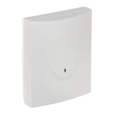
Satel INT-RX User manual

®
KEY FOBS RECEIVER EXPANSION MODULE
INT-RX
int-rx_en 05/09
The INT-RX expansion module is designed for operation in the intruder alarm systems. It can
work in conjunction with the SATEL made control panels: INTEGRA (with firmware version
1.05 or newer) and VERSA. The module enables key fobs to be assigned to the security
system users. Using the key fob enables up to 6 functions to be executed. The device
supports up to 248 key fobs manufactured by the SATEL company (the number of supported
key fobs depends on the control panel). Transmission from the key fob is dynamically
encoded using the KEELOQ® technology, which ensures both the operation safety and
immunity to spurious control signals, coming from other devices. The module can support all
key fobs manufactured by SATEL, but only the T-4 and P-4 models enable the module
features to be fully utilized.
1. Description of electronics board
+12V
COM CLK DAT
RS232
(TTL)
1
2345
67
Fig. 1. View of the INT-RX expansion module electronics board.
Explanations for the figure:
1 – antenna.
2 – superheterodyne receiver, high sensitivity, immune to spurious signals.
3 – tamper contact.
4 – two-color LED indicating as follows:
−steady green light – normal communication with the control panel;
−blinking green light – no communication with the control panel;
−steady red light – the expansion module is receiving transmission from a key fob
with good battery;
−blinking red light – the expansion module is receiving transmission from a key fob
with low battery.

2 INT-RX SATEL
5 – RS-232 port (TTL standard) for connection of the computer (the connection can be
made by using the cables included in the set manufactured by the SATEL and
designated DB9FC/RJ-KPL). The port enables updating of the module firmware.
6 – package of DIP-switches intended for setting an individual address of the module (see
section DIP-SWITCHES).
7 – red color LED indicating as follows:
−blinking light – data being exchanged with the control panel;
−steady light – no communication with the control panel.
Description of the terminals:
COM - common ground
CLK - clock
DAT - data
+12V - supply input
1.1 DIP-switches
The DIP-switches from 1 to 5 are to be used for address setting. The address must be
different from that of the other modules connected to the communication bus of alarm control
panel. In order to determine the expander address, add up the values set on individual
switches as shown in Table 1.
DIP-switch number 1 2 3 4 5
Numerical value
(for switch in ON position) 1 2 4 8 16
Table 1.
DIP-switches 6, 7 and 8 are not used.
3
22 (16h)
3
7 (07h)
Fig. 2. Examples of address setting (address 7 is required when working with the VERSA
control panels).
2. Installation and start-up
Disconnect power supply before making any electrical connections.
The INT-RX expansion module electronics board includes some static sensitive
components which should be discharged before installation. Avoid touching
the onboard components during installation.
The INT-RX expansion module is designed for indoor installation in spaces with normal
humidity of air. When selecting the place of mounting, take into consideration that thick
masonry walls, metal partitions, etc. reduce the range of radio signal. It is recommended that
the module be installed at a high point, so as to achieve a better radio communication range

SATEL INT-RX 3
and avoid the risk of the module being accidentally masked by personnel moving around the
site. The module installation place is to ensure protection against unauthorized access.
Connection to the control panel expander bus and to the power supply source is to be made
with a typical unscreened straight cable, as used in the security alarm systems (using the
“twisted pair” type of cable is not recommended). All the signal wires must be run in one
cable (running the signal wires in separate cables is not allowed).
1. Open the module housing.
2. Remove the module electronics board.
3. Make the cable entry holes in the housing rear panel.
4. Pass the cable through the prepared opening.
5. Secure the housing rear panel to the mounting surface.
6. Install the module electronics board in the housing.
7. Using the DIP-switches, set a suitable module address.
8. Connect the CLK, DAT and COM terminals by means of wires to the expander bus on the
control panel mainboard.
9. Connect the power wires to the +12V and COM terminals. The module supply voltage
need not necessarily be provided from the control panel mainboard. Modules installed far
from the control panel may be supplied locally from an independent power source
(additional power supply unit, expander with power supply).
10.Close the module housing.
11.Turn on power supply of the alarm system.
12.Start the identification function in the control panel.
3. Expansion module interaction with INTEGRA control panel
The key fob data are stored in each module. If you connect the module which contains key
fob related data to the alarm control panel, key fobs will be automatically assigned to the
users of that control panel. This will only apply to the users created up to that time.
Several INT-RX expansion modules can be connected to one control panel of the INTEGRA
series. The user can only have one key fob, but it will be supported by all modules. The key
fob related data are automatically written to all the INT-RX expansion modules.
Note: When connecting a new INT-RX expansion module to the INTEGRA system, in which
one such module is already operating, you should copy the data from one module to
the other so as to synchronize the key fob related data. The data can be copied by
using the COPY RX KEYFOBS function, available in the LCD keypad service menu
(
Æ
SERVICE MODE
Æ
STRUCTURE
Æ
HARDWARE
Æ
EXPANDERS
Æ
COPY RX KEYFOBS).
3.1 Adding and removing key fobs
Only the service (i.e. the person using the installer password code) is authorized to
add/remove the administrators’ key fobs. In case of the other users, the key fob can be
added/removed by the service (if authorized by the administrator), administrator, or a user
having the EDIT USER authority level.
In order to add a key fob, enter its serial number manually or read its serial number
during transmission to be sent on pressing the push-button.
Note: You cannot assign the same key fob to two users.
Available in the service menu of LCD keypad is the REM.RX KEY FOBS function (ÆSERVICE
MODE ÆSTRUCTURE ÆHARDWARE ÆEXPANDERS ÆREM.RX KEY FOBS), which makes it

4 INT-RX SATEL
possible to erase all key fob data in the INT-RX expansion modules connected to the control
panel. The same also applies to the information about zones assigned to the push-buttons in
individual users' key fobs. Removal of the key fob in any other way will not reset the push-
button settings.
3.1.1 Adding a key fob by means of LCD keypad
You can add key fobs by using the NEW RX KEY FOB function ([installer's code] ÆMASTERS
ÆNEW MASTER/EDIT MASTER ÆNEW RX KEY FOB or [code] ÆUSERS ÆNEW USER/EDIT USER
ÆNEW RX KEY FOB).
Actually, the key fob will only be added to the system after the function of
adding/editing administrator or user is completed, i.e. after the function is exited
by using the key and the made changes are saved by pressing the key.
Entering the serial number manually
1. Select ENTER MANUALLY from the list.
2. Enter the key fob number and press the key.
Reading the serial number during transmission
1. Select from the list the INT-RX module, by means of which a key fob is to be added.
2. Following the prompts displayed on the keypad, press the key fob button twice, and, when
the KEY FOB READ message appears, press .
3.1.2 Adding a key fob by means of DLOADXprogram
You can add key fobs by using the KEYFOBS INT-RX window (see Fig. 2). To open the
window, click on the KEYFOBS INT-RX item in the USERS menu, or on the EDIT KEYFOBS
button, which is available after selecting the INT-RX expansion module from the list of
devices (tab HARDWARE, window STRUCTURE). Prior to adding a new key fob, you have to
read the data from the module. In order to do so, click on the READ button. This will update
the information presented in the KEYFOBS INT-RX window. The name(s) of the module(s), the
control panel can communicate with (displayed at the top of the window – see Fig. 2), will be
highlighted in green.
Notes:
•After you click on the READ button, the program will read data from the INT-RX expansion
module having the lowest address. You should take this into consideration when
connecting new expansion modules to the control panel.
•When you click on the WRITE button before entering any change to the read data, the data
read from the expansion module having the lowest address will be written to all modules.
This function is useful when connecting new INT-RX expansion modules to the system in
which such modules are already functioning. It enables the key fob related data to be
synchronized (similarly as with the COPY RX KEYFOBS function, available in the service
menu of the LCD keypad).
•Where several INT-RX expansion modules are interfacing with the control panel, the loss
of communication with any of them will render the writing of key fob data to any module
impossible.
Entering the serial number manually
1. Click your mouse on the field in the S/N column, next to the name of the user to whom
you want to assign a key fob.

SATEL INT-RX 5
2. Enter the serial number of the key fob and confirm it by pressing ENTER. The background
color of the field where the serial number is displayed will change to pink.
3. Click on the WRITE button. The data will be written to the module(s). The background color
of the field where the serial number is displayed will change to white.
Fig. 2. View of the KEYFOBS INT-RX window in DLOADX program (interaction with INTEGRA
control panel).
Reading the serial number during transmission
1. Click your mouse on the field in the S/N column, next to the name of user to whom you
want to assign a key fob.
2. Click on the NEW button. The NEW window will open.
3. According to the command displayed in the window, press the key fob button, and, after
the key fob serial number appears in the window, press OK. The NEW window will close.
In the S/N column, the key fob serial number will be displayed next to the user name.
The background color of the field where the serial number is displayed will change to pink.

6 INT-RX SATEL
4. Click on the WRITE button to write the data to the module(s). The background color of the
field where the serial number is displayed will change to white.
3.1.3 Removing a key fob by means of LCD keypad
1. Start the REM.RX KEY FOB function ([installer code] ÆMASTERS ÆNEW MASTER/EDIT
MASTER ÆREM.RX KEY FOB or [code] ÆUSERS ÆNEW USER/EDIT USER ÆREM.RX KEY
FOB).
2. After the key fob number is displayed, press the key.
The key fob will only be removed from the system after completion of the
master/user editing function, i.e. after you exit the function by pressing the
key and save the made changes by pressing .
3.1.4 Removing a key fob by means of DLOADXprogram
1. Open the KEYFOBS INT-RX window (see Fig. 2).
2. Click on the READ button. The program will read out and display the data from the module.
3. Click your mouse on the field in the S/N column, next to the name of the user whose key
fob you want to remove.
4. Click on the REMOVE.
5. In the window which will be displayed, click on the YES button to confirm your intention to
remove the key fob. This will delete the key fob serial number. The background color of
the field where the serial number is displayed will change to pink.
6. Click on the WRITE button to write the data to the module(s). The background color of the
field where the serial number is displayed will change to white.
3.2 Controlling zones
In case of the INTEGRA control panels, the function is effected by controlling the zone status
in the system. By using a key fob you can control up to 6 zones in the security alarm system.
The zones should not physically exist and the type of line programmed for them must be
different from NOT USED and FOLLOW OUTPUT.You can program any function for these zones.
Pressing a key (or, simultaneously, two keys: 1 and 2 or 1 and 3) in the key fob will result in
violation of the zone (the zone will be violated as long as the key fob button is held down) and
a corresponding reaction of the control panel.
A button/combination of buttons can control one zone in the system. The zones are
individually assigned to the buttons/button combinations for each user. It can be done by
means of the LCD keypad or DLOADX program.
Pressing any button/combination of buttons in the key fob will generate an event informing
that a key fob has been used. In case of working in conjunction with the INTEGRA control
panel with firmware in version 1.06 or later, generating such events can be enabled or
disabled, so as to reduce the number of events in the system.
Note: The dependencies between key fob buttons and alarm system zones, which have
been defined for a user, will not be deleted after the key fob is removed (the only
exception being the REM.RX KEY FOBS function, available in the service menu of LCD
keypad). After a new key fob is added to the user, its buttons will control exactly the
same zones as those controlled by the buttons of removed key fob.
3.2.1 Assigning a zone to the button by means of LCD keypad
In LCD keypad, zones can be assigned to a button/combination of buttons by means of the
functions available when adding/editing administrator ([installer code] ÆMASTERS ÆNEW

SATEL INT-RX 7
MASTER/EDIT MASTER ÆBUTTON 1 / BUTTON 2 / BUTTON 3 / BUTTON 4 / BUTTON 1 and 2 /
BUTTON 1 and 3) or adding/editing user ([code] ÆUSERS ÆNEW USER/EDIT USER
ÆBUTTON 1 / BUTTON 2 / BUTTON 3 / BUTTON 4 / BUTTON 1 and 2 / BUTTON 1 and 3).
1. Start the selected function.
2. Using the Sand Tkeys, select a zone from the list or enter the zone number from the
keypad.
3. Press the key.
The zone will only be assigned to the button after completion of the master/user
adding/editing function, i.e. after you exit the function by using the key and
save the made changes by pressing .
3.2.2 Assigning a zone to the button by means of DLOADX program
In the DLOADX program, you can assign zones to a button/combination of buttons by using
the KEYFOBS INT-RX window (see Fig. 2).
1. Click on the READ button. The program will read and display data from the module.
2. Click on the selected user in the column corresponding to the button/combination of
buttons to which you want the zone to be assigned.
3. Using the keypad, enter the number of zone to be controlled by the button and confirm
with the ENTER key. The background color of the field where the zone number is
displayed will change to pink.
4. Click on the WRITE button. The data will be written to the module(s). The background color
of the field where the zone number is displayed will change to white.
3.2.3 Configuring event generation rules by means of LCD keypad [INTEGRA
1.06 or later]
Enabling/disabling generation of events for particular key fob buttons is possible by using the
RX EVENTS function, which is available when adding/editing administrator ([service code]
ÆMASTER ÆNEW MASTER/EDIT MASTER ÆRX EVENTS)or user ([code] ÆUSERS ÆNEW
USER/EDIT USER ÆRX EVENTS). To enable/disable the event generation feature, press any
numerical key. Event generation for the given button is enabled, when the symbol is
displayed in the upper line.
The new rules of generating events will only take effect after the function
of adding/editing administrator or user is completed, i.e. after the function is
exited by using the key and the introduced changes are saved by pressing
the key.
3.2.4 Configuring event generation rules by means of DLOADX program
[INTEGRA 1.06 or later]
Enabling/disabling generation of events for particular key fob buttons is possible by using
the KEYFOBS INT-RX window, after the key fob data have been read (see section ADDING
AKEY FOB BY MEANS OF DLOADXPROGRAM).
1. Click at the selected user in the column corresponding to the button/combination of
buttons for which you want to enable/disable the generation of events.
2. Using the SPACE button, enable/disable the event generation feature. The event
generation for the given button is disabled, if the 8symbol is shown next to the number of
zone controlled by the button (lack of the symbol means that the event generation is
enabled). Any modification of the settings will change the background color in part of the
field next to the zone number into pink.

8 INT-RX SATEL
3. Click on the WRITE button. The data will be written to the expander(s). Color in part of the
field next to the zone number will change to white.
4. Expansion module interaction with VERSA control panel
The key fob related data are stored in the expander. Connecting the expander which contains
key fob related data to the control panel will result in key fobs being automatically assigned to
the users of that control panel. This is only applicable to the users who have already been
created.
The functions which can be initiated by pressing a key fob button (combination of buttons 1
and 2 or 1 and 3) include:
•violating the selected control panel zone (the zone should not physically exist and the
type of line programmed for it must be different from NOT USED);
•arming/disarming and alarm clearing in selected partitions;
•triggering the panic, fire or medical assistance alarm;
•controlling the status of selected control panel output (enabling, disabling or switching the
output with function 15. CONTROLLED).
The functions can be individually assigned to buttons/combinations of buttons for each user.
Optionally, it will be possible to use templates predefined by the installer.
Pressing a button/combination of buttons by the user can generate an event that will be
written to the control panel memory irrespective of the event connected with the function
which is initiated by means of the key fob (global option STORE KEY FOB EVENTS).
4.1 Adding/removing key fobs and assigning functions to the buttons
Key fobs can be added /removed by the service as well as by users having the USERS
EDITING authority level.
In order to add a key fob, enter its serial number manually or read its serial number
during transmission to be sent on pressing the push-button.
Note: You cannot assign the same key fob to two users.
The key fobs may be removed individually for each user or for all users at once (the function
is only available in the keypad). Removing the user amounts to removing the key fob.
4.1.1 Adding a key fob and assigning a function by means of keypad
Adding a key fob and assigning a function to its keys is possible during the procedure of
adding / editing user ([code] X2. USERS X1. NEW USER / 2. EDIT USER). Both procedures
are described in the user manual for VERSA alarm control panels.
4.1.2 Adding a key fob and assigning a function by means of DLOADX program
Adding a key fob and assigning a function to its keys is possible in the "Versa – Structure"
window, "Hardware" tab, after selecting the INT-RX expansion module in the list of devices.
Before you proceed to adding a new key fob, data must be read from the expander. For this
purpose, click your mouse on the READ button. The key fobs can be added in the same way,
as when working with the INTEGRA control panel.
After adding the key fob, functions will be automatically assigned to the buttons, according to
the template defined for the user's authority level. By default, the assigned functions can be
substituted by other ones:
1. Click at the selected user in the column corresponding to the button (combination of
buttons), to which you want the function to be assigned.

SATEL INT-RX 9
2. Right-click your mouse. A drop-down menu will be displayed, where you can select the
required function. You can also enter the number of function by using the keyboard (the
numbers of all available functions are shown in the programming manual and in the user
manual for VERSA control panels) and confirm with the ENTER key. The background
color of the field in which the zone number is shown will change into pink.
3. Click on the WRITE button. The data will be written into the expander. The background
color of the field in which the zone number is shown will change into white.
4.1.3 Removing key fobs by means of keypad
Removing a key fob is possible during the user editing procedure ([code] X2. USERS
X2. EDIT USER), the description of which is included in the user manual for VERSA control
panels.
Note: Removing a user key fob by means of keypad does not mean automatically deleting
the dependency between key fob buttons and functions executed by using them.
The REMOVE KEY FOBS,available in the service menu (SERVICE MENU X2. HARDWARE
X1. KPDS.&EXPS. X9. REMOVE K-FOBS) makes it possible to clear all key fob related data in
the INT-RX expander connected to the control panel. This is also applicable to the
information on functions assigned to the buttons of individual users' key fobs.
4.1.4 Removing key fobs by means of DLOADX program
Removing a key fob is possible in the "Versa – Structure" window, "Hardware" tab, after
selecting the INT-RX expansion module in the list of devices. The key fob can be removed in
the same way, as when working with the INTEGRA control panel.
5. Specifications
5.1 INT-RX expansion module
Operating range in open area ................................................................................. up to 100 m
(any obstacles between transmitter and receiver will reduce operating range of the device)
Supply voltage ................................................................................................... 12 V DC ±15%
Standby current consumption ..........................................................................................25 mA
Maximum current consumption........................................................................................30 mA
Working frequency range ........................................................................433.05 – 434.79 MHz
Housing dimensions ......................................................................................72 x 118 x 24 mm
Environmental class................................................................................................................. II
Working temperature range ..............................................................................-10 °C...+55 °C
Weight................................................................................................................................. 74 g
5.2 T-4 key fob
Battery type.................................................................................................................. 23A 12V
Housing dimensions ........................................................................................35 x 70 x 15 mm
Environmental class................................................................................................................. II
Working temperature range ..............................................................................-10 °C...+55 °C
Weight................................................................................................................................. 27 g

10 INT-RX SATEL
DECLARATION OF CONFORMITY
Product:
INT-RX – remote control set for INTEGRA and VERSA
control panels.
Manufacturer: SATEL spółka z o.o.
ul. Schuberta 79
80-172 Gdańsk, POLSKA
tel. (+48) 0-58 320-94-00
fax. (+48) 0-58 320-94-01
Product description:433 MHz remote control set consisting of T-4 transmitters and a receiver,
compatible with P-2, P-4, T-2, T-4 key fobs, intended for use with INTEGRA and VERSA control
panels as a part of intruder alarm system.
The product is in conformity with the following EU Directives:
EMC 2004/108/EC
R&TTE 1999/5/EC
The product meets the requirements of harmonized standards:
EMC: EN 55022:1998;EN 50130-4:1995; ETSI EN 301 489-1 v 1.4.1; ETSI EN 301 489-3 v 1.4.1
ETSI EN 300 220-2 v 2.1.1
EN 60950
Gdańsk, Poland 2009-03-13 Head of Test Laboratory:
MichałKonarski
The latest EC declaration of conformity and product approval certificates are available for
downloading on website www.satel.pl
SATEL sp. z o.o.
ul. Schuberta 79
80-172 Gdańsk
POLAND
tel. + 48 58 320 94 00
www.satel.pl
Table of contents
Other Satel Control Unit manuals

Satel
Satel ETHM-2 User manual

Satel
Satel STAM-1 TRNK User manual

Satel
Satel SATELLINE-M3-TR1 User manual

Satel
Satel GSM-X User manual

Satel
Satel ETHM-1 Plus User manual

Satel
Satel ETHM-1 Plus User manual

Satel
Satel GSM LT-1 User manual

Satel
Satel VIVER User manual

Satel
Satel CA-64 ADR-MOD User manual

Satel
Satel INT-GSM User manual