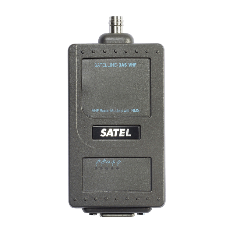
Satel SATELLINE-2ASxE User manual

SATELLINE-2ASxE
RADIO MODEM
User Guide
Versio 2.0

SATELLINE-2ASxE
User Guide, Version 2.0
1
IMPORTANT NOTICE
All rights to this manual are owned solely by SATEL OY (referred to in this user guide as SATEL). All
rights reserved. The copying of this manual (without the written permission from the owner) by
printing, copying, recording or by any other means, or the full or partial translation of the manual
to any other language, including all programming languages, using any electrical, mechanical,
magnetic, optical, manual or other methods or devices is forbidden.
SATEL reserves the right to change the technical specifications or functions of its products, or to
discontinue the manufacture of any of its products or to discontinue the support of any of its
products, without any written announcement and urges its customers to ensure, that the information
at their disposal is valid.
SATEL software and programs are delivered ”as is”. The manufacturer does not grant any kind of
warranty including guarantees on suitability and applicability to a certain application. Under no
circumstances is the manufacturer or the developer of a program responsible for any possible
damages caused by the use of a program. The names of the programs as well as all copyrights
relating to the programs are the sole property of SATEL. Any transfer, licensing to a third party,
leasing, renting, transportation, copying, editing, translating, modifying into another programming
language or reverse engineering for any intent is forbidden without the written consent of SATEL.
SATEL PRODUCTS HAVE NOT BEEN DESIGNED, INTENDED NOR INSPECTED TO BE USED IN
ANY LIFE SUPPORT RELATED DEVICE OR SYSTEM RELATED FUNCTION NOR AS A PART OF
ANY OTHER CRITICAL SYSTEM AND ARE GRANTED NO FUNCTIONAL WARRANTY IF THEY ARE
USED IN ANY OF THE APPLICATIONS MENTIONED.
Salo, FINLAND 2004

SATELLINE-2ASxE
User Guide, Version 2.0
2
RESTRICTIONS ON USE
SATELLINE-2ASxE radio modems have been designed to operate on frequency ranges, the exact
use of which differs from one region and/or country to another. The user of a radio modem must
take care that the said device is not operated without the permission of the local authorities on
frequencies other than those specifically reserved and intended for use without a specific permit.
SATELLINE-2ASxE
(370…470 MHz) is allowed to be used in the following countries, either on
licence free channels or on channels where the operation requires a licence. More detailed
information is available at the local frequency management authority.
Countries*: AT, AU, BE, CA, HR, DK, EE, FI, FR, DE, GR, HK, HU, IS, IE, IT, LV, LT, MY, NL, NO,
PL, RO, SG, ZA, ES, SE, CH, TR and GB
WARNING!
Users of SATELLINE-2ASxE radio modem in North America should be aware, that due
to the allocation of the frequency band 406.0 – 406.1 MHz for government use only, the use of
radio modem on this frequency band without a proper permit is strictly forbidden.

SATELLINE-2ASxE
User Guide, Version 2.0
3
PRODUCT CONFORMITY
Hereby, SATEL Oy declares that SATELLINE-2ASxE radio modem is in compliance with the essential
requirements (radio performance, electromagnetic compatibility and electrical safety) and other
relevant provisions of Directive 1999/5/EC. Therefore the equipment is labelled with the following
CE-marking. The notification sign informs user that the operating frequency range of the device is
not harmonised throughout the market area, and the local spectrum authority should be contacted
in prior of use.
0523

SATELLINE-2ASxE
User Guide, Version 2.0
4
TABLE OF CONTENTS
IMPORTANT NOTICE........................................................................................................1
RESTRICTIONS ON USE....................................................................................................2
PRODUCT CONFORMITY .................................................................................................3
TABLE OF CONTENTS ......................................................................................................4
1 SATELLINE-2ASxE Radio Data Modem .........................................................................6
1.1 Radio data modem ..................................................................................................6
1.2 RS-232 pin connections ...........................................................................................8
1.3 Technical specifications............................................................................................9
2 Transmission with the Radio Modem .........................................................................10
2.1 Transmission .........................................................................................................10
2.2 Reception ..............................................................................................................11
2.2.1 RSSI signal.......................................................................................................12
2.3 Delays during data transmission ............................................................................12
2.4 Basic connection between two radio modems........................................................ 13
3 Asynchronous Data Transmission and Data Speed ....................................................14
3.1 Asynchronous character.........................................................................................14
3.1.1 Special BREAK Character .................................................................................15
3.2 Data speed............................................................................................................15
4 Repeater Station Using One Radio Modem................................................................15
5 Using Addresses in Data Communication..................................................................16
5.1 General.................................................................................................................16
5.2 A connection between two points...........................................................................18
5.3 A system with one base station and several substations..........................................18
5.4 A system with one repeater station ........................................................................19
5.4.1 The alternating addresses of a pair of radio modems .......................................19
5.5 A system with several repeater stations ..................................................................20
5.6 A repeater chain using dual addressing .................................................................22
6 Test Mode.................................................................................................................23
6.1 TX Carrier Test ....................................................................................................23
6.2 TX Data 80 B.......................................................................................................23
6.3 TX Data 10 kB .....................................................................................................23
7 Programming the SATELLINE-2ASxE ..........................................................................24
7.1 General ..............................................................................................................24
7.2 Programming mode ............................................................................................24

SATELLINE-2ASxE
User Guide, Version 2.0
5
7.2. Setting the radio frequency .................................................................................25
7.2.2 Setting the channel spacing ...........................................................................25
7.2.3 Setting the data interface properties ..............................................................26
7.2.4 Setting the addresses.....................................................................................27
7.2.5 Setting the receiver status ..............................................................................28
7.2.6 Setting the repeater function..........................................................................28
7.2.7 Setting the SL-command function...................................................................28
7.2.8 Setting the RTS line functions .........................................................................29
7.2.9 Setting the special functions...........................................................................29
7.2.10 Setting the TX Start delay ...............................................................................30
7.2.11 Setting the Test Mode ....................................................................................30
7.3 SL commands......................................................................................................31
7.3.1 Setting the addresses.....................................................................................31
7.3.2 Setting the radio channel...............................................................................31
7.3.3 Saving of the current setup ............................................................................32
8 Forming the SL Commands.......................................................................................33
8.1 Forming a packet to change addresses ................................................................33
9 Multi Modem Data Systems.......................................................................................35
9.1 Transmission sequences ......................................................................................35
9.2 Polling ................................................................................................................35
9.3 Multi Master........................................................................................................35
10 Planning a Radio Modem Network .........................................................................36
10.1 Factors affecting the quality and maximum distance of a radio connection ...........36
10.2 Radio field strength ..........................................................................................37
11 Installation ................................................................................................................38
11.1 RS-232 Interface ..............................................................................................39
11.2 Power supply ....................................................................................................40
11.3 Antenna installation .........................................................................................40
12 Equipment .............................................................................................................43
12.1 Connecting antennas to radio modems ............................................................43
12.1.1 Hand portable equipment..............................................................................43
12.1.2 Equipment installed in vehicles ......................................................................43
12.1.3 Base station...................................................................................................43
12.2 Cables.................................................................................................................44
12.2.1 RF cables .......................................................................................................44
12.2.2 Interface cables .............................................................................................44
13 Check List ..............................................................................................................45

SATELLINE-2ASxE
User Guide, Version 2.0
6
1 SATELLINE-2ASxE Radio Data Modem
1.1 Radio data modem
RS-232
SIGNALS
POWER
SUPPLY
MODEM
+
CONTROL
LOGIC
TRANSMITTER
SYNTHESIZER
RECEIVER
RF-
SIGNAL
D-15 TNC
The SATELLINE-2ASxE radio data modem consists of a synthesized 450 MHz transceiver and a
modem board housed in a compact aluminium enclosure. The modem has a RS-232 interface
which provides the flexibility to connect it to a wide variety of data networks and terminal
equipment.
The operation of SATELLINE-2ASxE is similar to a cable although data transmission is half duplex.
When planning a radio data modem installation it is important to take into account the slight delays
of the radio modems and possible radio interference. The most important RS-232 signals are
indicated by LEDs.
Typical applications of the SATELLINE-2ASxE are:
xReplacing an RS-232-cable in situations where installation of a cable is difficult,
expensive or even impossible
xData transmission to and from mobile or portable terminals
xWireless alarm transfer
xTelemetry
xRemote control
xTransferring text to displays
xFor use with the Global Positioning System (GPS)
xetc.
With two SATELLINE-2ASxE radio data modems it is easy to establish point to point connections.
The power level of the transmitter is 1 W. It is possible to reach distances of 2 to 40 km depending
on topographical conditions and antenna locations. Country specific laws of radio communication
must always be followed.
The radio data modem operates well in data networks where the same channel is used by several
mobile terminals. In such systems the protocol can be either a polling protocol, in which the data

SATELLINE-2ASxE
User Guide, Version 2.0
7
communication is controlled by the base station, or a multimaster protocol, in which any of the
radio modems can initiate data transmission when the radio channel is free.
Due to the incorporation of unique synthesizing techniques the SATELLINE-2ASxE is also suitable for
systems with several base stations using different channels. The mobile substations can easily
change the frequency for communication with the different base stations. By using this method the
coverage area of a system can be enlarged without incurring extra delays due to the capacity of the
radio channels.
The handshaking procedure of the SATELLINE-2ASxE interface is PC compatible. Most
telecommunications programs can be used with the modem in order to transmit data. This feature
together with the possibility of programming the radio data modem via the RS-232 interface (see
paragraph 7) makes SATELLINE-2ASxE a product with many application possibilities in wireless data
communication.

SATELLINE-2ASxE
User Guide, Version 2.0
8
1.2 RS-232 pin connections
Pin Signal Direction Level Description
1 DTR IN RS-232 Data Terminal Ready
Operates as an ON/OFF switch
2 CD OUT RS-232 Carrier Detect
Indicates a signal on the radio channel
exceeding the sesitivity level of the modem
(also interference signal)
3-
4-
5 RSSI OUT Analog
signal
Received signal strength indicator
6 CTS OUT RS-232 Clear To Send
Indicates that the radio modem is ready to
accept data on the TD line
7 , 8 GND - Ground Operating voltage negative pole and ground
reference for all signals
9 RD OUT RS-232 Receive Data
10 DSR OUT RS-232 Data Set Ready
Indicates the "ON" state of the modem
11 TD IN RS-232 Transmit Data
12 MODE IN open/gnd Mode Selection *)
13 RTS IN RS-232 Request to Send **)
14,
15
VB - Voltage Operating voltage positive pole
*) When pin 12 is open, the radio data modem is in DATA MODE and ready for receiving and
transmitting data. When the line is connected to ground, the radio data modem is in
PROGRAMMING MODE
**) RTS line: not used in normal data transmission, can be programmed separately for special
characteristics

SATELLINE-2ASxE
User Guide, Version 2.0
9
1.3 Technical specifications
The equipment complies with the ETS 300 113 and ETS 300 279 specifications .
TRANSCEIVER
Frequency Range 370...470 MHz
Channel Spacing 12.5 kHz/20 kHz or 25 kHz
Number of Channels 160/100 or 80
Frequency Stability < ± 1.5 kHz
Type of Emission F1D
Method of modulation FSK
Transmitter
Carrier Power 1 W (+30 dBm) / 50 ohm
Carrier Power Stability + 2 dB / - 3 dB
Frequency Deviation ± 1.8 kHz or ± 2.5 kHz
Adjacent Channel Power according to ETS 300 113
Spurious Radiations according to ETS 300 113
Receiver
Sensitivity < -115 dBm (BER < 10 E-3)
Co-channel rejection > - 8 dB
Adjacent channel selectivity > 60 dB / >70 dB or >70 dB
Intermodulation attenuation > 65 dB
Spurious radiations < 2 nW
DATA MODEM
Interface RS-232
Interface Connector D15 connector, female
Data speed 1200 - 4800 bps (12.5 / 20 kHz channel)
1200 - 9600 bps (25 kHz channel)
Modulating Signal NRZ
Data formats Asynchronous data
Character length: 10 or 11 bits
GENERAL
Operating voltage + 9 ...+ 30 Vdc
Power consumption 2.5 VA typical (Receive)
6.6 VA typical (Transmit)
0.05 VA typical (when DTR is "0")
Temperature range -25 °C...+55 °C
Antenna Connector TNC, 50 ohm, female
Construction Aluminium enclosure
Size H x W x D 137 x 67 x 29 mm
Installation plate 130 x 63 x 1 mm
Weight 250 g

SATELLINE-2ASxE
User Guide, Version 2.0
10
Labelling information:
Ser.no. 98290014 Fc: 468.2000 MHz
Init. Settings: 468.2000 MHz / 25 kHz
SATEL OY
Tel: +358-2-7777800, Fax: +358-2-7777810
xSerial number
xFrequency, centre frequency, tuning range +/- 1 MHz
xInitial settings: Frequency / channel spacing
xContact information of manufacturer or distributor
2 Transmission with the Radio Modem
2.1 Transmission
The SATELLINE-2ASxE is ready to transmit data within 300 ms after the supply voltage is switched
on and the DTR line is in the "ON" state.
There are three different methods of initiating data transmission:
1. Transmission based on CTS or CD handshaking
2. Data connected directly to the TD line
3. Using TX control of RTS line
If the connection between the radio data modems breaks in the middle of the transmission i.e. as a
result of a weak signal, the radio modems can be reconnected by interrupting the transmission for a
moment.
1. Transmission based on CTS or CD handshaking
Handshaking should be used when the user needs to ensure that the radio channel is free and the
modem is ready to transmit data:
xCD line turns "ON" if the radio channel is occupied (i.e. the strength of another
transmission or interference exceeds a preset sensitivity level)
xCTS line turns ”OFF” if the radio modem has recognised a valid synchronization pattern
or if the modem is for any reason unprepared for transmission

SATELLINE-2ASxE
User Guide, Version 2.0
11
NOTE!
CTS does not follow the CD line. CTS line is not affected by interference or signals from other
radio equipment (= programmable data squelch)
.
Only real received data turns CTS "OFF".
This feature makes data transmission possible also in presence of slight interference.
2. Data connected directly to the TD line
It’s not necessary to use handshaking if the following conditions are met:
xThe channel is completely free from other transmissions and overlapping transmissions are
prevented
xData packets are short (less than 500 bytes)
xIf transmitting long data packets (more than 500 bytes) the terminal should be set to use two (2)
stop bits and the radio modem in a state where the total number of bits in a character is one
less than in the terminal. (Prevents the buffer from filling up.)
3. Using the RTS line to control transmission (RTS set to TX control)
RTS line activates transmission and prevents the radio modem from going into the reception mode.
The radio modem sets the CTS line when it is ready to accept data for transmission.
2.2 Reception
The SATELLINE-2ASxE is ready to receive data within 300 ms after the power supply is switched on
and the DTR line is in the "ON" state.
Data appears on the RD line as soon as the modem receives a valid data transmission. Start of
reception can also be detected from the CTS and CD lines. (See 2.1)
In case of interference or external equipment affecting the functions of the radio modem it can be
necessary to prevent the radio modem from receiving. In systems with simplex data transmission,
reception can be switched off at the transmitting end. This prevents possible external interference
from preventing transmission. (See 7.2.8)
In systems with several radio modems the reception of data can be stopped with the RTS line by
activating the "RD line control" in the programming mode. (Compare with 7.2.8) When the RTS
line is not active the reception of data to the RD line is disabled. Transmission is not possible as
long as data transmission is present on the channel.
In systems with several radio modems the reception of data can be stopped with the RTS line by
activating "Reception Control" in the programming mode. (Compare with 7.2.8) When the RTS
line is not active reception is stopped (CTS line indicates current status) and transmission is possible.

SATELLINE-2ASxE
User Guide, Version 2.0
12
2.2.1 RSSI signal
Received Signal Strength Indicator, RSSI, (D connector pin 5) can be used for the approximate
determination of the radio signal strength on the current channel.
In the following figure is the typical RSSI voltage (V) as a function of the signal level (dBm). In
practise signal level exceeds –25dBm only if the distance to a transmitting modem is less than 10
meters.
0
0,5
1
1,5
2
2,5
3
3,5
4
OFF
-120
-118
-116
-110
-100
-90
-80
-70
-60
-50
-40
-30
-25
-20
-15
-10
2.3 Delays during data transmission
When using a radio data modem, certain delays occur in data transmission and reception.
The delays at different data speeds are:
1200 bps 2400 bps 4800 bps 9600 bps
Wakeup time DTR OFF/ON 300 ms
Rx/Tx turn around time on the radio interface 24 ms 12 ms 6 ms 3 ms
Rx/Tx turn around time on the RS-232 interface 0 ms
Tx/Rx turn around time*) 40-270 ms 20-150 ms 10-90 ms 5-60 ms
Tx/Rx turn around time typical 65 ms 47 ms 30 ms 20 ms
Delay of a point-to-point connection **) 61-65 ms 47- 49 ms 30-32 ms 18-19 ms
*) depends on the length of the data packet and data speed differences between the data terminal
and the radio data modem
**) TD line radio modem 1 / RD line radio modem 2 delay

SATELLINE-2ASxE
User Guide, Version 2.0
13
2.4 Basic connection between two radio modems
In order to create a connection between two terminals transmitting and receiving data the radio
modems should be programmed and wired as described below. In this case there is no external
protocol in use.
Basic setup of the programming menu
Two wire cable
TD
RD
SGND
DTR
+Vb
GND
11
9
7
1
15
8
+Vb GND
RADIO MODEM
FUSE 630 mA slow
TD
RD
2
3
7
25-PIN D-CONNECTOR
SGND
TD
RD
2
3
5
9-PIN D-CONNECTOR
SGND
****** SATEL OY Salo, Finland tel: +358-2-7777800
****** SATELLINE-2ASxE SW Version 1.00
Center Frequency 468.0000 MHz
Lower Freq. Limit 467.0000 MHz
Upper Freq. Limit 469.0000 MHz
1) Current Frequency 468.2000 MHz
2) Channel Spacing 12.5 kHz
3) Data 4800 bps 10 bits
4) Addresses tx = 0000 / 0000 (hex) off
rx = 0000 / 0000 (hex) off
5) Receiver on
6) Repeater Function off
7) SL-commands off
8) RTS-line off
9) Special Functions off
A) TX Start delay (ms) 0000 (hex)
T) Tests off
Q) Quit
Enter selection >

SATELLINE-2ASxE
User Guide, Version 2.0
14
3 Asynchronous Data Transmission and Data Speed
If the character length or data speed is incorrectly set, errors will appear in transmission. At
reception they appear as "error characters" or as incorrect operation of the modem.
The data settings of each station in the system should all be the same.
3.1 Asynchronous character
The asynchronous data characters are in accordance with the ANSI-standard (e.g. ASCII), and
according to the length of the character are divided into two groups. The character length is 10
or 11 bits including start, data, parity and stop bits.
Radio data modems repeat the parity bit as such. The composition of a character is shown below
(compare to 7.2.3):
START 7 DATA PARITY STOP
START 8 DATA STO P
e.g. 7,E,1
8,N,1
START 8 DATA STO PPARITY
START 9 DATA S TO P
10 BIT
11 BIT
e.g. 8,E,1
9,N,1

SATELLINE-2ASxE
User Guide, Version 2.0
15
3.1.1 Special BREAK Character
A BREAK character is used in some special protocols e.g. ABB RCOM protocol. The BREAK
character is the first character of the data string with 0 level. It is longer than one normal
asynchronous character.
BREAK DATA
The transmitting radio modem recognises the special start element, BREAK, at the beginning of a
data string. At reception side the radio modem generates a BREAK in a similar position. The exact
length of the BREAK character is not transmitted.
3.2 Data speed
The data speed of the SATELLINE-2ASxE is 1200 - 9600 bit/s with the channel spacing of 25 kHz
and 1200 - 4800 bit/s with the channel spacing of 12.5 and 20 kHz respectively.
The data speed can be selected in the programming mode.
4 Repeater Station Using One Radio Modem
Short data packets of 135 B maximum can be repeated using one radio modem. The repeater
function has to be set on in the programming mode. In the repeater mode the radio modem works
as an independent unit. When a radio modem is only used as a repeater it only requires a power
supply and an antenna. No other equipment is needed.
A radio modem working as a repeater can also be used for transmission and reception of data. In
the repeater mode the radio modem receives data in the same way as usual. However, at the same
time it memorizes the received data. After finishing the reception of data the radio modem does not
turn back to the state where it observes the interface lines. It immediately transmits the received and
memorized data on the same channel and with the same settings as received. When transmitting
data from the RS-line the functions of the radio modem do not differ from a normal radio modem.
There can be several repeaters in the same system and under the same base station. The repeater
stations can also be grouped in a chain, wherein the message goes via several repeater stations. It
is necessary to use addresses of the radio modem in a system with several repeater stations.

SATELLINE-2ASxE
User Guide, Version 2.0
16
5 Using Addresses in Data Communication
5.1 General
It is possible to use addresses in both transmission (TX) and reception (RX). An address consists of
two data characters (altogether 16 bits). The addresses can either be the same in both directions or
when necessary the transmission and the reception addresses can also be different.
Each modem has two pairs of addresses, the primary (1) and the secondary (2) addresses. If only
one pair is necessary both address pairs should be set equal i.e. TX1=TX2 and RX1=RX2.
The secondary addresses are normally useful only if the radio modem is used as a
repeater.
The addresses can be selected separately for both directions. It is also possible to transfer the
received address to the RS interface.
An address consists of the first two characters of a data packet that the radio modem adds to every
sent packet and/or checks from every received packet. (compare to paragraph 7.3.1 SLAxy
command, where ADD H corresponds to x and ADD L corresponds to y)
ADD H ADD L DATA
Transmission:
Data
A
ddress Data
Data
Data
Fig 1 Transmission addressing has been set
ON. The radio modem will add the primary
TX address to the beginning of the data
packet.
Fig 2 Transmission addresssing has been set
OFF. The radio modem will transmit the data
packet as such.

SATELLINE-2ASxE
User Guide, Version 2.0
17
Reception:
Address Data
Data
Address Data
Fig 3 Reception addressing has been set ON
and either the primary or secondary RX
address of the radio modem is identical to the
address of the received data packet.
The radio modem will remove the address
and send the actual data to the RS-232
interface.
However, if the ”RX Address to RD-line”
(programming mode) is on, the radio modem
does not remove the address.
Fig 4 Reception addressing has been set
ON, but both the primary and secondary RX
addresses of the radio modem are different
from the address of the received data packet.
Data does not appear on the RS-232
interface.
Data
Data
Data
Address Data
Address Data
ERROR
Fig 5 Reception addressing
has been set OFF.
The radio modem will
transfer all received data to
the RS-232 interface.
Fig 6 Reception addressing
has been set OFF.
The radio modem will
consider the characters of the
address as a part of the data
and will send all the
characters to the RS-232
interface.
Fig 7 Reception addressing
has been set ON but there is
no address in the data packet.
Data will appear on the RS-
232 interface ONLY if the first
2 characters of the data
match either of its own RX
address. The radio modem
will remove those 2 characters
of data.

SATELLINE-2ASxE
User Guide, Version 2.0
18
5.2 A connection between two points
In connecting two points it is advisable to set both the receiving and the transmitting addresses
equal in both radio modems. This is the easiest way to control the addresses and the risk of
interference from other systems working in the same area is minimal.
It’s not necessary to use addressing if a special radio channel is reserved for use in the area or if the
terminal takes care of addressing.
5.3 A system with one base station and several substations
In a system with several substations it is necessary for the base station to know to which of the
substations the message has to be sent and from which substation the message is received. When
planning the system there are at least two different possibilities to make use of the addresses in the
radio modem. It is also possible that the terminals take care of addressing and in this case the
feature of the radio modem is not needed.
The address of the base station can always be changed when transmitting from one substation to
another. In this case the base station can only listen to one substation at a time. In a polling system
it is possible to use this arrangement because the radio modems communicate with each other in
pairs.
In a system with Carrier Sense Multiple Access (CSMA) it is not possible to use addressing at the
base station as it would prevent the base station from hearing all the substations. It is useful to
change the address of the base station according to the substation in a polling system. It is the
terminal of the base station that should take care of the addition of addresses and checking of data
packets.
In these applications the radio modem at the base station is left without an address and the radio
modems at the substations are set with both the transmitting and the receiving address. The
software of the base station must be able to treat the addresses given by the base station and to
add the addresses of the substations to the data packet.

SATELLINE-2ASxE
User Guide, Version 2.0
19
5.4 A system with one repeater station
In systems with several repeater, sub and base stations it is necessary to use addresses in the radio
modems especially if there is more than one repeater station. A system with only one repeater
station can be built without addressing. However, the message will be duplicated on the
communication route (the base station hears the messages from both the substation and the
repeater station).
There are at least two alternative ways to use addressing depending on the programmability of the
terminal equipment and the number of repeater stations and their positions to each other.
5.4.1 The alternating addresses of a pair of radio modems
When neither the terminal nor the substations are able to generate address fields, but they can
recognize the message addressed to them, the addresses of the radio modems can be alternating.
The transmission (TX) and reception (RX) addresses of the radio modems alternate according to the
following table:
Base station
address
The address of
repeater station 1
and substations of
the base station
The address of the
substations of the
repeater station 1
TX address address 1 address 2 address 1
RX address address 2 address 1 address 2
In a system using alternating addresses the routing of data to a specific radio modem is set at the
time of installation. The order of the addresses must be set according to the wished routing of data.
Please note that in systems with alternating addresses the base station and the substations hear their
own messages repeated.
Table of contents
Other Satel Radio Modem manuals

Satel
Satel SATELLINE-3ASd Epic Pro 35W User manual

Satel
Satel SATELLINE-3ASd Epic Pro 35W User manual

Satel
Satel SATELLINE-3AS VHF YM5000 User manual

Satel
Satel SATEL-EASY PRO+ User manual

Satel
Satel Proof-TR489 User manual

Satel
Satel Compact-4BT User manual

Satel
Satel SATELLINE-3AS VHF YM5000 User manual

Satel
Satel Proof-TR4 User manual

Satel
Satel SATELLINE-3ASd Epic Pro 35W User manual

Satel
Satel SATEL-EASy+ YM6015 User manual