SATO TURN-O-MATIC User manual

TURN-O-MATIC
INSTALLATION GUIDE
WIRED SYSTEM
www.satoamerica.com
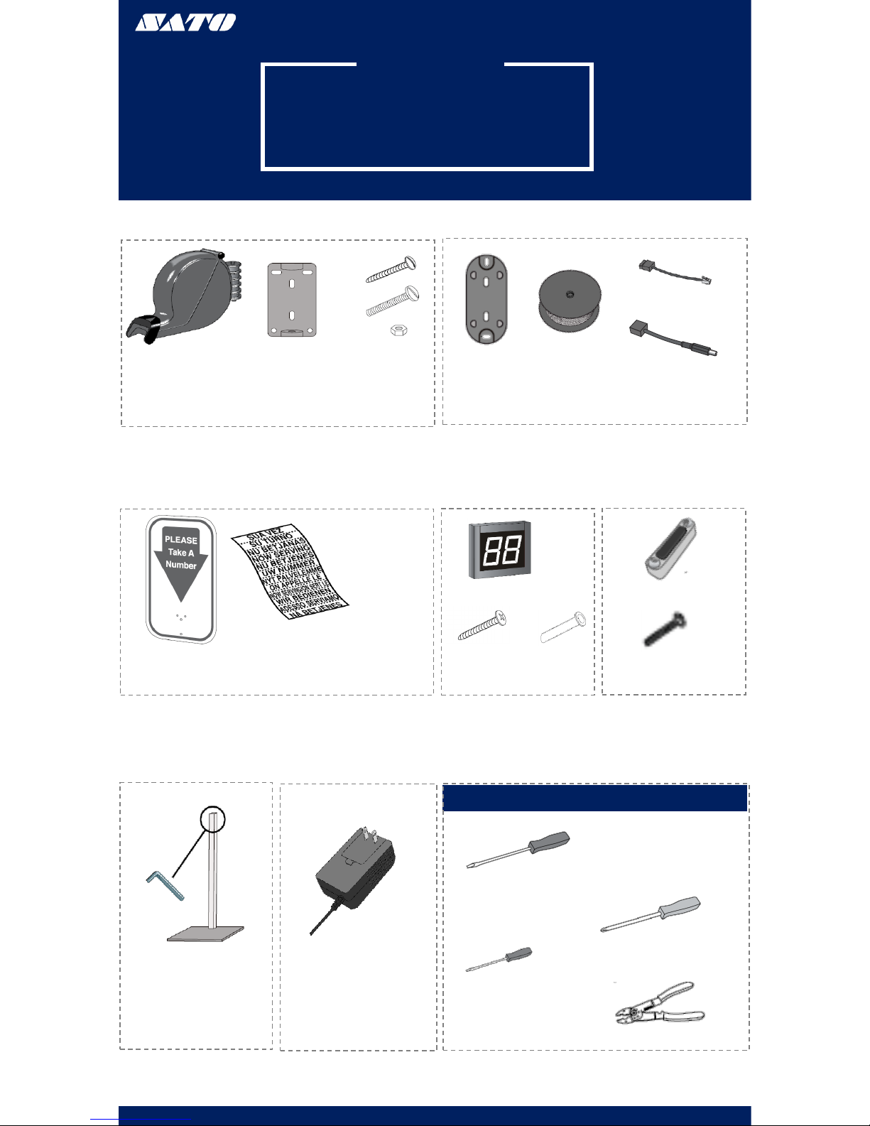
PARTS LIST
SYSTEM PARTS LIST
WIRED SYSTEM
(1) Dispenser (1) Dispenser
Mounting
Bracket
(3) Large Slotted
Screw
(2) Large Slotted
Bolt
(2) Nut
(1) Flat Display
Wall Mount
Bracket
(100’)
Electrical Wire
(1) Power
Connector
(1) AC Power Supply
(1) Mounting Stand
(1) TOM Sign (1) Label Sheet
(1) 2 Digit Indicator
(2) Wall
Anchor
(2) Large
Phillips
Screw
TOOLS NEEDED
Large Flathead Screwdriver
Phillips Screwdriver
Mini Flathead Screwdriver
www.satoamerica.com
(2) Data Cable
Connector
Wire Cutters
(3) Push Button
(6) Slotted Screws
PARTS LIST
OPERATION & INSTALLATION
DISPENSER
OPERATION
1. The customer takes a number from the dispenser;
this number will indicate the customer’s spot in the
queue
2. The customer will be notified of their turn when
their number is displayed on the indicator
3. The associate will use the programmed (+) push
button to advance the display one number at a time
4. Press and hold the (+) pushbutton to advance the
numbers by tens
5. Use the programmed (-) push button to go back one
number at a time
NUMBER DISPENSER
Number dispenser may be mounted to either the wall or
stand
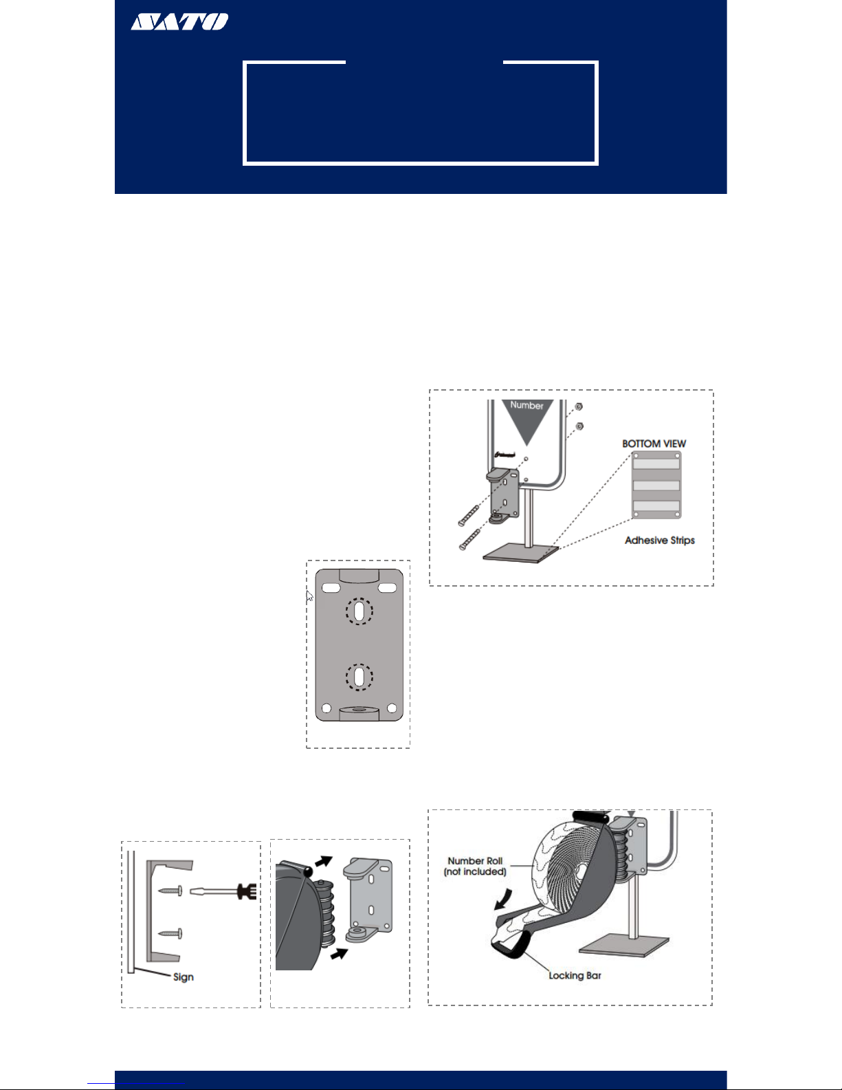
WALL MOUNTING
1. Measure and mark the
mounting holes on the wall
using the dispenser
mounting bracket as a
template (Figure 1)
2. Drill holes using a 3/16” to
5/16” drill bit
3. Use the wall anchors if
mounting the dispenser to a
surface other than solid
wood
4. Position the sign and
dispenser mounting bracket
over the holes in the wall
and fasten with two slotted
screws (Figure 2)
5. Snap the dispenser into the
mounting bracket (Figure 3)
Figure 1
Figure 2 Figure 3
STAND MOUNTING
1. Position the mounting stand in the desired
location on a countertop
2. Align the holes in the sign and the mounting
bracket with the holes in the post. Push the two
large slotted bolts through bracket and sign and
secure with the provided nuts (Figure 4)
3. Snap the dispenser into the mounting bracket
(Figure 3)
Figure 4
LOADING DISPENSER
1. Pull the locking bar down to open the dispenser
2. Place the roll of tickets in the dispenser, making
sure the numbers are facing up and the roll out
from the bottom (Figure 5)
3. Pull the end of the roll of tickets through the
dispenser and securely shut the dispenser by
snapping the locking bar back into place
Figure 5
www.satoamerica.com
PARTS LIST
OPERATION & INSTALLATION
DISPLAY
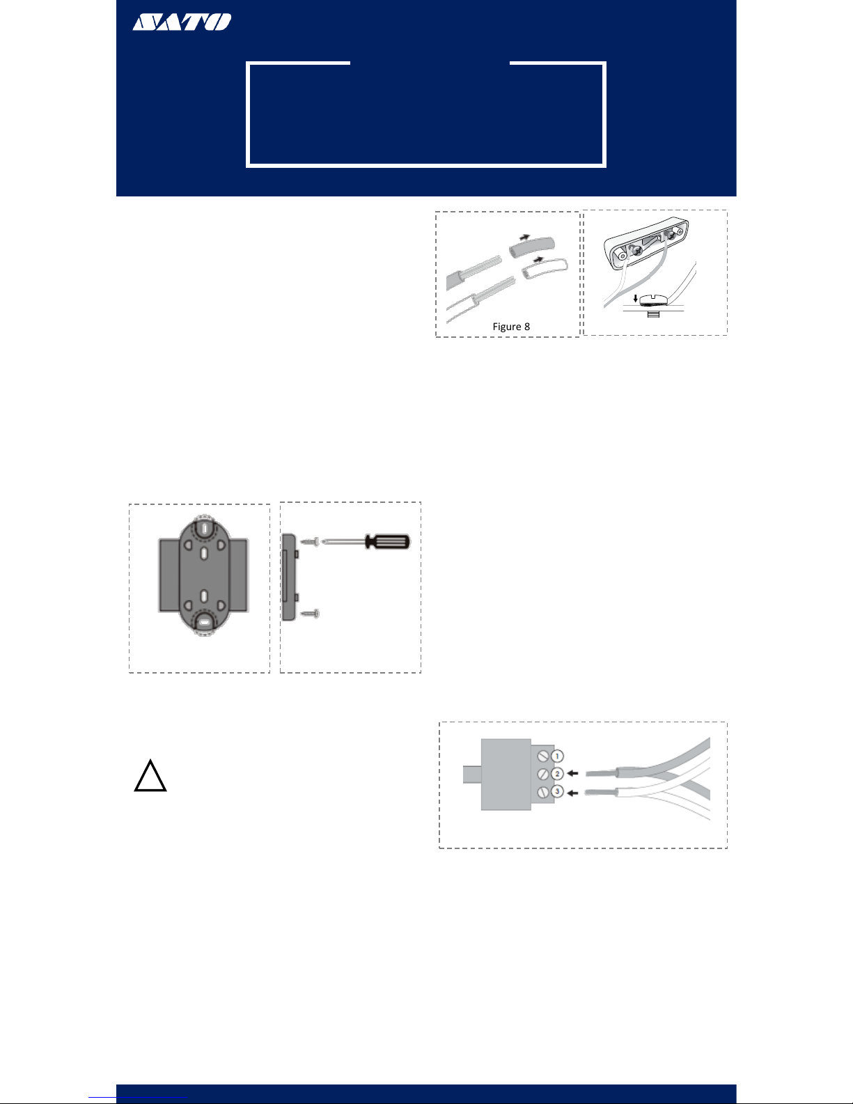
WALL MOUNTING
1. Identify a suitable position for the indicator assuring
the display is easily seen by the customers
2. Measure and mark the mounting holes on the wall
using the display wall mount bracket as a template
(Figure 6)
3. Drill holes using a 5/16” drill bit
4. Use the wall anchors if mounting the indicator to a
surface other than solid wood wall
5. Position the display wall mount bracket over the
drilled holes and secure with two large Phillips screws
(Figure 7)
www.satoamerica.com
Figure 6 Figure 7
WIRING
PUSH BUTTONS
WARNING! Electrical Shock hazard. Do not
connect the display to power until all push
buttons and power connections are complete.
Serious electric shock, injury or death may result.
Figure 8
Figure 10
ELECTRONIC DISPLAY
The Take-A-Number System includes three push
buttons. Set two push buttons to advance numbers
and one to go back to a previous number.
!
1. Cut a length of electrical wire to reach from
each push button location to display
2. Strip wire ends about ½” (Figure 8)
3. On the underside of one push button:
Loosen screws. Wrap one wire end around
one screw post and wrap the other wire
end around the other screw post. Tighten
the screws to secure wires (Figure 9)
4. Secure push button to surface using the
two included slotted screws (Optional)
5. Repeat steps 1-3 with the two remaining
push buttons
Figure 9
WIRING PUSH
BUTTONS TO DATA
CONNECTORS
1. 1. Strip wire ends about ½” for all three
push buttons. (Figure 8)
2. Each data connector has three numbered
ports. Loosen screws on ports 2 and 3 with
a mini flathead screwdriver
3. For (+) push buttons: Twist the same color
wires together from two of the push
buttons (copper to copper, silver to silver).
Insert the twisted wires into ports 2 and 3
on one data connector. Tighten screws to
secure wires (Figure 10)
4. For (-) push button: Use the wire from one
remaining push button. Insert the wires
into ports 2 and 3 on the second data
connector. Tighten screws to secure the
wires (Figure 10)
PLUGGING DATA
CONNECTORS INTO
DISPLAY
1. 1. Plug the data connector with two push
buttons attached into the (+) jack on the
back of the display (Figure 11)
2. Plug the other data connector with the
single push button attached into the (-) jack
on the back if the display (Figure 11)

OPERATION & INSTALLATION DISPLAY CONT.
www.satoamerica.com
Figure 11
PLUGGING DATA
CONNECTORS INTO
DISPLAY CONT.
3. Mark which push button is plugged into the (+)
and (-) jacks
(+) Push button advances the numbers
(-) Push button goes back to previous numbers
Figure 12
WIRING AC POWER
SUPPLY
1. Cut a length of electrical wire that will reach from
the electrical outlet to the display location
2. Strip wire ends about 1.5” (Figure 12)
3. Loosen both screws on the bottom of the AC power
supply
4. Attach one wire to each screw post underneath the
metal plates. Tighten screws to secure wires (Figure
13)
WARNING! Do not connect the display to power
until all push buttons and power connections are
complete. Serious electrical shock, injury or
death may result.
!
Figure 13
WIRING AC POWER
SUPPLY TO POWER
CONNECTOR
1. The power connector has two parts. Loosen both
small screws using the mini flathead screwdriver
2. Insert one wire end into each port. Tighten
screws to secure wires (Figure 14)
Figure 14
3. Plug the power connector into either of the two
power receptacles located on the back of the display
(Figure 15)
4. Plug the AC power supply into the nearest outlet
Figure 15
SET-UP
SOUND & TONE VOLUME
Use a mini flathead screwdriver to change the tone and
volume switches on back of the display (Figure 12)
TONE
No Sound: 1-OFF1 2-OFF
Single Tone: 1-OFF 2-ON
Double Tone: 1-ON 2-OFF
Triple Tone: 1-ON 2-ON
VOLUME
Low Volume: 3-OFF 4-OFF
Medium Volume: 3-ON 4-OFF
High Volume: 3-OFF 4-ON
Highest Volume: 3-ON 4-ON
Figure 16
OPERATION & INSTALLATION DISPLAY CONT.
www.satoamerica.com
DISPLAY START-UP
Once powered on, the display will show a number of
messages upon start-up (Figure13)
DISPLAY SHOWS
Program Version: “P-”, then number
TOM-Net Address: “ad’, then 51 or 21
Last Number Displayed When The Power Has Been
Disconnected: Number, (00 if first-time start-up)
Error Message if Displayed is Set as a Duplicate Master: “Ed”
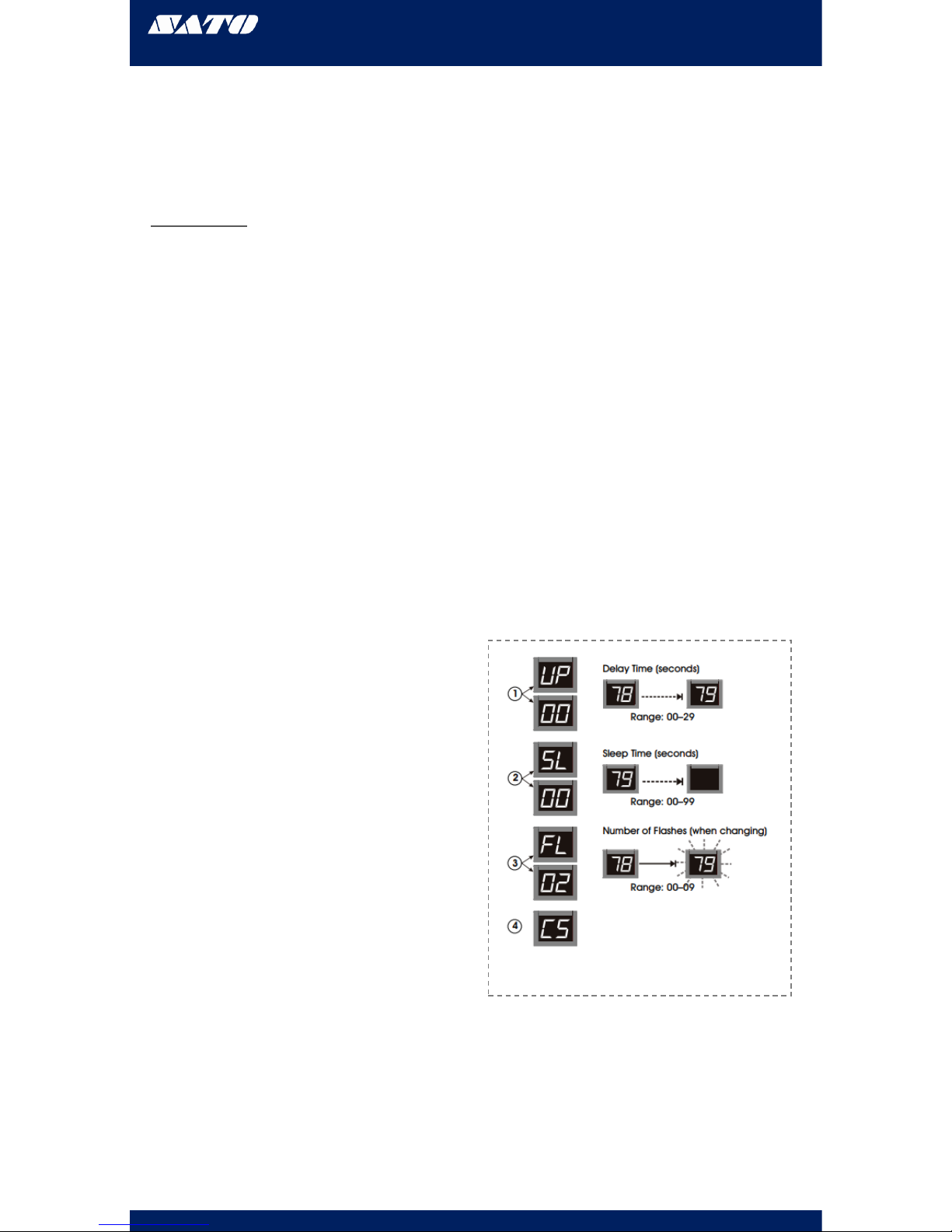
OPTIONAL
DISPLAY SET-UP
•To enter setup options, make sure the
display is unplugged.
•Hold down (+) on the wireless push button
and plug the display back in.
•Release (+) when the display reads “UP”
SET DISPLAY UPDATE DELAY:
•Display shows “UP” followed by the current
delay time in seconds, (ex. “00”). Press (+) on
the wireless push button to increase the delay
one second at time
•After three without pushing the button, the
set display sleep time “SL” appears
SET DISPLAY SLEEP TIME:
•Display shows “SL” followed by the current
delay time in minutes. (The display shits off
after a set periods of the time with no button
pushes.) Press (+) on the wireless push
button to increase the delay before the
display goes into sleep mode one minute at a
time
•After three seconds without pushing the
button the set display flashes and “FL”
appears
SET DISPLAY FLASHES WHEN NUMBER CHANGES:
•Display shows “FL” followed by the current
setting showing number of flashes. Presses (+)
on the wireless push button to increase the
number of times the display will flash when the
number changes one flash at a time
After three seconds without pushing the button,
the display shows “CS” and saves the new settings
to memory
Figure 17
OPTIONAL
DISPLAY SET-UP CONT.
Table of contents
Other SATO Dispenser manuals


