SATO TURN-O-MATIC User manual
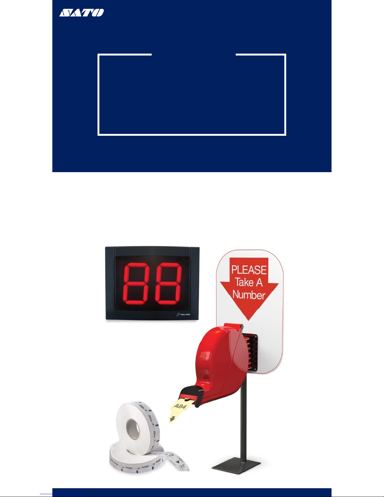
TURN-O-MATIC
INSTALLATION GUIDE
WIRELESS
www.satoamerica.com
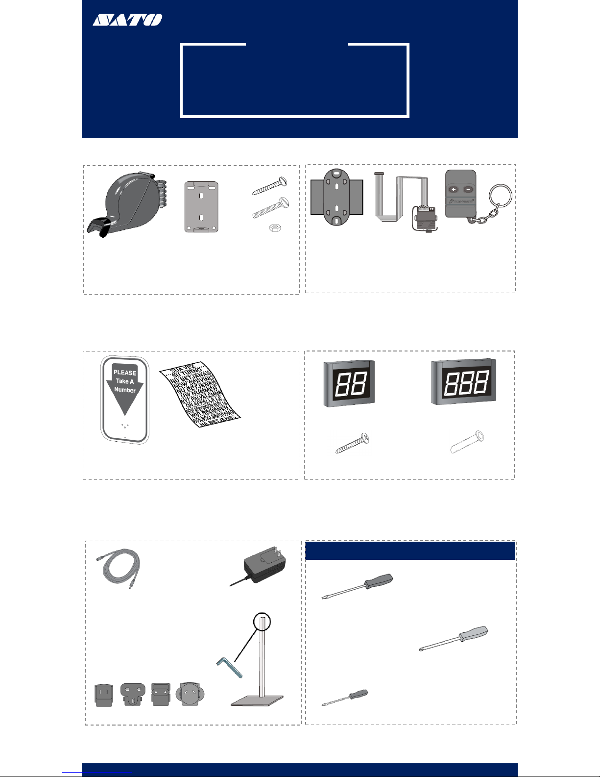
PARTS LIST
SYSTEM PARTS LIST
WIRELESS SYSTEM
(1) Dispenser (1) Dispenser
Mounting
Bracket
(3) Large Slotted
Screw
(2) Large Slotted
Bolt
(2) Nut
(1) Display
Wall Mount
Bracket
(1) Wireless
Receiver (2) Wireless
Push Button
(1) Power Extension Cable (1) AC Power Supply
(4) Country Outlet Adapter (1) Mounting Stand
(1) TOM Sign (1) Label Sheet
(1) 2 Digit Indicator (1) 3 Digit Indicator
(2) Wall Anchor
(2) Large Phillips Screw
TOOLS NEEDED
Large Flathead Screwdriver
Phillips Screwdriver
Mini Flathead Screwdriver
www.satoamerica.com

PARTS LIST
OPERATION & INSTALLATION
DISPENSER
OPERATION
1. The customer takes a number from the dispenser;
this number will indicate the customer’s spot in the
queue
2. The customer will be notified of their turn when
their number is displayed on the indicator
3. The associate will use the wireless remote to
advance the display by pressing the (+) button or to
turn the display back by pressing the (-) button
4. If the associate wishes to advance the display by
tens they will press and hold the (+) button
MOUNTING
The dispenser can be mounted to either the wall or stand
WALL MOUNTING
1. Measure and mark the
mounting holes on the wall
using the dispenser
mounting bracket as a
template (Figure 1)
2. Drill holes using a 3/16” to
5/16” drill bit
3. Use the wall anchors if
mounting the dispenser to a
surface other than solid
wood
4. Position the sign and
dispenser mounting bracket
over the holes in the wall
and fasten with two slotted
screws (Figure 2)
5. Snap the dispenser into the
mounting bracket (Figure 3)
Figure 1
Figure 2 Figure 3
STAND MOUNTING
1. Position the mounting stand in the desired
location on a countertop
2. Align the holes in the sign and the mounting
bracket with the holes in the post. Push the two
large slotted bolts through bracket and sign and
secure with the provided nuts (Figure 4)
3. Snap the dispenser into the mounting bracket
(Figure 3)
Figure 4
LOADING DISPENSER
1. Pull the locking bar down to open the dispenser
2. Place the roll of tickets in the dispenser, making
sure the numbers are facing up and the roll out
from the bottom (Figure 5)
3. Pull the end of the roll of tickets through the
dispenser and securely shut the dispenser by
snapping the locking bar back into place
Figure 5
www.satoamerica.com
PARTS LIST
OPERATION & INSTALLATION
DISPLAY
MOUNTING
1. Identify a suitable position for the indicator assuring
the display is easily seen by the customers
2. Measure and mark the mounting holes on the wall
using the display wall mount bracket as a template
(Figure 6)
3. Drill holes using a 5/16” drill bit
4. Use the wall anchors if mounting the indicator to a
surface other than solid wood wall
5. Position the display wall mount bracket over the
drilled holes and secure with two large Phillips screws
(Figure 7)
Figure 6 Figure 7
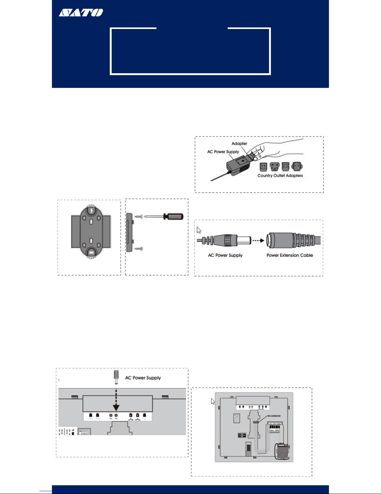
AC POWER SUPPLY CONT
2. Choose the appropriate country outlet adapter
and slide it into the AC power supply (Figure 9)
www.satoamerica.com
AC POWER SUPPLY
1. Plug the AC Power supply into either if the two power
receptacles located on the back of the display
(Figure 8)
Figure 4
Figure 9
Figure 10
3. If required, attach the 10 ft. power extension
cable (Figure 10)
4. Plug the AC power supply into the nearest outlet
WIRELESS RECEIVER
1. Attach the pin connector of the wireless
receiver to the pins located on the back of
display (Figure 11)
2. Remove backing from adhesive strips on
the wireless receiver and mount it on the
back of the display
Figure 11

OPERATION & INSTALLATION DISPLAY CONT.
SET-UP
SOUND & TONE VOLUME
Use a mini flathead screwdriver to change the tone and
volume switches on back of the display (Figure 12)
TONE
No Sound: 1-OFF1 2-OFF
Single Tone: 1-OFF 2-ON
Double Tone: 1-ON 2-OFF
Triple Tone: 1-ON 2-ON
VOLUME
Low Volume: 3-OFF 4-OFF
Medium Volume: 3-ON 4-OFF
High Volume: 3-OFF 4-ON
Highest Volume: 3-ON 4-ON
Figure 12
DISPLAY START-UP
Once powered on, the display will show a number of
messages upon start-up (Figure13)
DISPLAY SHOWS
Program Version: “P-”, then number
TOM-Net Address: “ad’, then 51 or 21
Last Number Displayed When The Power Has Been
Disconnected: Number, (00 if first-time start-up)
Error Message if Displayed is Set as a Duplicate Master: “Ed”
Figure 13
OPTIONAL
DISPLAY SET-UP
•To enter setup options, make sure the
display is unplugged.
•Hold down (+) on the wireless push button
and plug the display back in.
•Release (+) when the display reads “UP”
SET DISPLAY UPDATE DELAY:
•Display shows “UP” followed by the current
delay time in seconds, (ex. “00”). Press (+) on
the wireless push button to increase the delay
one second at time
•After three without pushing the button, the
set display sleep time “SL” appears
SET DISPLAY SLEEP TIME:
•Display shows “SL” followed by the current
delay time in minutes. (The display shits off
after a set periods of the time with no button
pushes.) Press (+) on the wireless push
button to increase the delay before the
display goes into sleep mode one minute at a
time
•After three seconds without pushing the
button the set display flashes and “FL”
appears
SET DISPLAY FLASHES WHEN NUMBER CHANGES:
•Display shows “FL” followed by the current
setting showing number of flashes. Presses (+)
on the wireless push button to increase the
number of times the display will flash when the
number changes one flash at a time
After three seconds without pushing the button,
the display shows “CS” and saves the new settings
to memory
Figure 14
www.satoamerica.com
PARTS LIST
PROGRAMMING
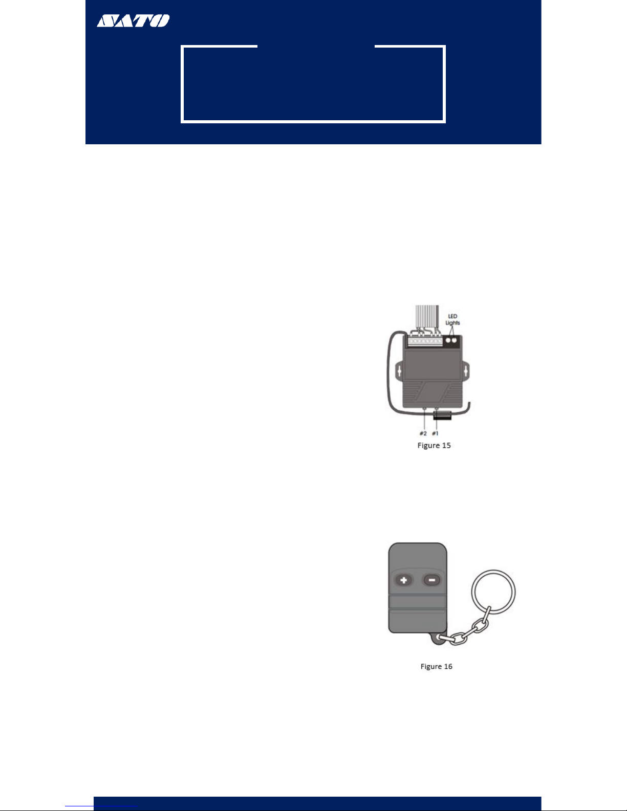
WIRELESS PUSH BUTTON
PROGRAMMING ADDITIONAL
WIRELESS PUSH BUTTONS
1. Press #1 on the wireless receiver and hold for three
seconds. The green LED light on the back of the wireless
receiver will start blinking (Figure 15)
2. Release #1 on the wireless receiver. Then press the (+)
button on the wireless push button. The green LED light
will stop blinking (Figure 16)
3. Press #2 on the wireless receiver and hold for three
seconds. The red LED light on the back of the wireless
receiver will start blinking (Figure 15)
4. Release #2 on the wireless receiver. The press the (-)
button on the wireless push button. The red LED light will
stop blinking (Figure 16)
www.satoamerica.com
DELETING
WIRELESS PUSH BUTTONS
1. Press #1 on the wireless receiver and hold for three
seconds. Release and press #1 again for three seconds.
The code has been deleted. (Figure 15)
2. Press #2 on the wireless receiver for three seconds.
Release and press #2 again for three seconds. The code
has been deleted (Figure 15)
Table of contents
Other SATO Dispenser manuals


