SATO CT424i User manual

CT4i Operator’s Manual
Read this Operator’s Manual before and during usage of the above
product. Keep this document handy for future reference.
CT 408i/412i/424i

Be sure to ask your dealer about our maintenance contracts
to ensure peace of mind during your usage of SATO products
Version: SI-CT4xxi-01rA-21-12-07OM
© Copyright 1994 – 2007
SATO CORPORATION
Warning: This equipment complies with the requirements in Part 15 of FCC rules for a Class A
computing device. Operation of this equipment in a residential area may cause unacceptable
interference to radio and TV reception requiring the operator to take whatever steps are necessary to
correct the interference.
All rights reserved. No part of this document may be reproduced or issued to third parties in any form
whatsoever without the express permission of SATO. The materials in this document are provided for
general information and are subject to change without notice. SATO assumes no responsibilities for any
errors that may appear.
WARNING
THE EQUIPMENT REFERENCED IN THIS DOCUMENT COMPLIES WITH THE REQUIREMENTS IN PART 15
OF FCC RULES FOR A CLASS B COMPUTING DEVICE. OPERATION OF THIS EQUIPMENT IN A
RESIDENTIAL AREA MAY CAUSE UNACCEPTABLE INTERFERENCE TO RADIO AND TV RECEPTION.
For SATO office locations worldwide, visit ww.satoworldwide.com

This page is intentionally left blank.

TABLE OF CONTENTS
INTRODUCTION...............................................................................................................1-1
About this manual........................................................................................................1-2
General Description.....................................................................................................1-3
TECHNICAL DATA...........................................................................................................2-1
Interface Selection.......................................................................................................2-6
RS232C high-speed Serial Interface (25-pin)..............................................................2-6
IEEE1284 Parallel Interface.........................................................................................2-8
Universal Serial Bus (USB)..........................................................................................2-9
Bluetooth......................................................................................................................2-9
Local Area Network (LAN) Ethernet.............................................................................2-10
802.11G Wireless ........................................................................................................2-11
All Interfaces................................................................................................................2-13
ACK/NAK Protocol.......................................................................................................2-13
Status5 Return.............................................................................................................2-13
INSTALLATION................................................................................................................3-1
Overview......................................................................................................................3-2
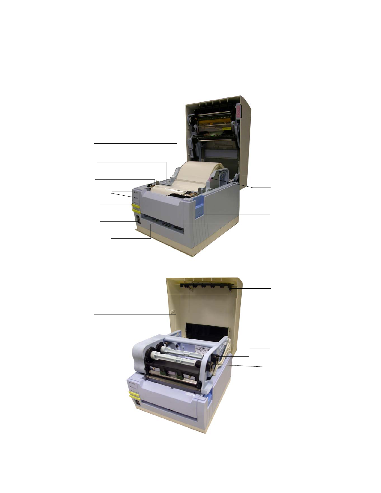
Unpacking & Parts Identification..................................................................................3-5
Printer Installation........................................................................................................3-6
Site Location................................................................................................................3-6
Media Selection ...........................................................................................................3-6
Media Loading: Rolled Paper.......................................................................................3-6
Ribbon Loading ...........................................................................................................3-7
Loading Fanfold Paper.................................................................................................3-8
Label Sensing..............................................................................................................3-9
Operational Mode Selection.........................................................................................3-10
Continuous Mode.........................................................................................................3-10
Tear-off Mode ..............................................................................................................3-10
Cutter Mode.................................................................................................................3-10
Dispense Mode............................................................................................................3-10
Linerless Mode.............................................................................................................3-10
PRINTER CONFIGURATION...........................................................................................4-1
Configuration Modes....................................................................................................4-2
Operating Panel...........................................................................................................4-2
The Rear Panel............................................................................................................4-3
The Configuration Panel ..............................................................................................4-4
Operational Modes.......................................................................................................4-8
Adjustment of Reference Print position........................................................................4-16
Potentiometer Adjustments..........................................................................................4-18
Printing Test Labels .....................................................................................................4-20
Printing Factory/Service Test Prints.............................................................................4-21

TROUBLESHOOTING......................................................................................................5-1
Troubleshooting Guide.................................................................................................5-2
Interface Troubleshooting ............................................................................................5-6
Test Print Troubleshooting...........................................................................................5-8
Hex Dump....................................................................................................................5-8
Test Label Printing.......................................................................................................5-8
MAINTENANCE................................................................................................................6-1
Cleaning procedures....................................................................................................6-2
Adjustment Procedures................................................................................................6-3
Adjusting the Print Quality............................................................................................6-3
Cleaning the Print Head, Platen and Rollers................................................................6-4
Releasing/Replacing the Print Head............................................................................6-6
Cleaning the Sensor.....................................................................................................6-7

Unit 1: Introduction
CT4i Operator’s Manual 1-1
INTRODUCTION
• About This Manual
• General Description
• Control Features

Unit 1: Introduction
CT4i Operator’s Manual 1-2
ABOUT THIS MANUAL
This manual is laid out consistent with the product discussed and provides all of the information required for printer
installation, configuration, operation, and light maintenance. Refer to this product’s Programming Reference
document for instructions on printer programming through a host system.
This manual also incorporates the use of special information boxes. Examples of these boxes and the type of
information provided in each, are below.
A comprehensive Table Of Contents provided at the front of this manual facilitates rapid movement within. The
contents identify the different Units, Chapters, and some Sections. Each references the page number of their
commencement.
The pages of this manual have embedded headers and footers to assist the user in identifying his or her exact
position within the manual. The header provides the unit number followed by its name. The footer identifies the
product on the left, the page number in the center, and the manual’s part number to the right side of the page.
Page enumeration is two-part with each separated by a hyphen. The first character set references the Unit and the
second identifies the page number within that unit. Page numbers begin with the numeral one (1) at the beginning
of a new unit and ascend sequentially.
WARNING: PROVIDES INFORMATION THAT, IF UNHEEDED, MAY RESULT IN
PERSONAL INJURY.
CAUTION: PROVIDES INFORMATION THAT, IF UNHEEDED, MAY RESULT IN
EQUIPMENT DAMAGE.
ATTENTION: Provides information that is deemed of special importance but will not
result in personal injury or product damage if unheeded.
NOTE: Provides helpful hints to assist in performing the tasks at hand.
LCD DISPLAY: Provides the specific display that should be visible on the LCD at that
point.

Unit 1: Introduction
CT4i Operator’s Manual 1-3
GENERAL DESCRIPTION
The compact CT4i Series printers are designed for use in medium-volume labeling applications demanding a low
footprint, crisp print quality of up to 600dpi; hardware versatility, ease of use, and great reliability. Its antibacterial
chassis also positions it ideally for clinical environments. The printer’s main parts are described below.
Ribbon Take-up
spindle
Spring loaded holder
for ribbon mechanism
Support stand for lifting
ribbon mechanism
upward
Label Holder
Cover release
Top cover
Power switch
LED/DIP switches
and potentiometers
ONLINE button
FEED button
Power/Error LEDs
Platen Roller
Label Sensor
Label Holder
Label Holder release
knob
Print Head
Fanfold loading window
Front cover and
compartment for
optional cutter
Ribbon Supply
spindle
Figure 1-1, Primary Parts (Direct Thermal model)
Figure 1-2, Primary Parts (Thermal Transfer model)

Unit 1: Introduction
CT4i Operator’s Manual 1-4
This page is left blank intentionally.

Unit 2: Technical Data
CT4i Operator’s Manual 2-1
TECHNICAL DATA
• Physical Characteristics
• Environmental Specs
• Power Supply
• Processing
• Printer Language
• Interface Modules
•Print
•Sensing
•Media
• Ribbon
• Regulatory Approvals
• Character Font Capabilities
• Barcode Capabilities

Unit 2: Technical Data
CT4i Operator’s Manual 2-2
PHYSICAL CHARACTERISTICS
Width 7.8 in. (198 mm)
Height 8.8 in. (225 mm)
Depth 7.1 in. (181 mm)
Weight 5.5 lbs (2.5 Kg) excluding AC adaptor
ENVIRONMENTAL (EXCLUDING MEDIA)
Operating Temperature/Humidity 5° to 35°C @ 30 to 80%RH
Storage Temperature/Humidity -5° to 60°C @ 30 ~ 90%RH, non-condensing (NA for media)
POWER SUPPLY
Input Voltage (AC) 100-240 Volts AC +/- 10%, 50/60 Hertz
Rated Input voltage: 25 V DC
Rated current: 1.5 A
Input Voltage (DC) Rated voltage: 24.0 VDC - 25.25 VDC
Rated current: 2 A (Current peak: 13 A)
Power Consumption 90 Watts (when print ratio is 30%)
PROCESSING
CPU 32 Bit RISC
Flash ROM 4 Megabytes
SDRAM 16 MB
PRINTER LANGUAGE
Standard SATO Barcode Printer Language (SBPL) 4.3
INTERFACES
Standard configurations Either 1) USB 2.0 with RS-232C or
2) USB 2.0 with LAN (10BASE-T/100BASE-TX Automatic Switching)
User installable Optional Inter-
face Board
(USB with RS232C model only) IEEE1284, 802.11g Wireless Wi-Fi, Bluetooth

Unit 2: Technical Data
CT4i Operator’s Manual 2-3
PRINT
Method DT models: Direct Thermal only
TT models: Thermal Transfer and Direct Thermal (switchable)
Maximum Speed (selectable) 2, 3, 4, 5, 6 Inches Per Second (CT408i)
2, 3, 4 Inches Per Second (CT412i)
2, 3 Inches Per Second (CT424i)
Resolution CT408i: 203 Dots Per Inch (8 dpmm)
CT412i: 305 Dots Per Inch (12 dpmm)
CT424i: 600 Dots Per Inch (23.6 dpmm)
Maximum Print Width 104 mm
Maximum Print Length 400 mm
SENSING
Gap Sensitivity Adjustable
Reflective Eye-Mark Sensitivity Adjustable
Head Open Fixed
Media Out Fixed (always enabled)
Ribbon Out Fixed (always enabled)
MEDIA
Width Media Width: 1 - 4.6inches (25 - 115mm) (28 - 118mm with backing paper)
Note: For Dispensing Mode, specifications may vary depending on the requirements
Length 0.6 - 15.66 inches (15 - 397mm)
With backing paper: 0.72 - 16 inches (18 - 400mm)
Type Direct Thermal / Thermal Transfer depending on print model (DT or TT)
Roll stock / Fan-fold
Configuration Roll stock: Max. outer diameter: 4.4 inches (110 mm)
Wound face-out, Inner diameter of roll: 1.6 inches (40 mm)
Fanfold: Max. stack height: 4 inches (100 mm) (external supply)
Thickness 0.0032 - 0.0076 inches (0.08 - 0.19 mm)
Wind Direction Face Out
RIBBON
Width 4.44 inches (111mm)
Length 3937 inches (100M)
Wound Face Out
Core Diameter 0.508 inches (12.7 mm)

Unit 2: Technical Data
CT4i Operator’s Manual 2-4
REGULATORY
USA/Canada UL60950-1(2001), CSA C22.2 No.60950-1-03
China CCC (GB4943-2001)
EU CE, Nemko (EN60950-1)
Singapore SS337:2001
Korea MIC, EK (only AC-Adapter applicable)
Radiation Noise
FCC Part 15, Subpart B, Class B (USA/Canada)
GB9254-1998, GB17625.1-2003 (China)
CE (EN55022, EN55024, EN61000-3-2/-3) (EU)
CISPR22, CISPR24 (reference standard, Singapore)
KN22, KN24 (Korea)
WLAN/RFID/Bluetooth
FCC15B / FCC15C (USA/Canada)
SRRC (China)
Wireless LAN/Bluetooth (2.45GHz)
R&TTE (EN300 328 V1.4: 2003-04, EN301 489 V1.4.1: 2002-08);
HF Band: RFID (13.56MHz) (EU)
R&TTE (EN300-330)
IDATS (Singapore)
MIC (Korea)
Antibacterial Finish JISZ2801 (control panel and enclosure)
Environmental (RoHS)
Chromium: below 0.1%
Lead: below 0.1%
Mercury: below 0.1%
Cadmium: below 0.01%
Polybrominated Bipheny (PBB): below 0.1%
Polybrominated Diphenyl Ether (PBDE): below 0.1%
CHARACTER FONT CAPABILITIES
MATRIX FONTS
XU 5 dots W x 9 dots H (Helvetica)
XS 17 dots W x 17 dots H (Univers Condensed Bold)
XM 24 dots W x 24 dots H (Univers Condensed Bold)
OA Font (OCR-A) CT408i: 15 dots W x 22 dots H
CT412i: 22 dots W x 33 dots H
CT424i: 44 dots W x 66 dots H
OB Font (OCR-B) CT408i: 20 dots W x 24 dots H
CT412i: 30 dots W x 36 dots H
CT424i: 60 dots W × 72 dots H
AUTO SMOOTHING FONTS
XB 48 dots W x 48 dots H (Univers Condensed Bold)
XL 48 dots W x 48 dots H (Sans Serif)
DOWNLOADABLE FONTS
Up to 1600 characters of 64 bit x 64 bit sized font can be downloaded to Flash Memory
Expansion up to 12 x in either the X or Y coordinates.
Character Pitch Control
Line Space Control
Journal Print Facility
0, 90, 180, and 270-degree rotation

Unit 2: Technical Data
CT4i Operator’s Manual 2-5
BARCODE CAPABILITIES
Linear Bar Codes UPC-A/E, EAN, CODABAR, CODE39, CODE93, CODE128, UCC/EAN128, Interleaved
2of5, Industrial 2of5, Matrix 2of5, MSI, BOOKLAND, POSTNET, EAN/UCC symbol
Two Dimensional QR code (Ver8.1), PDF417 (Ver2.4), MAXI code (Ver3.0), Data Matrix (Ver1.3) *Only
ECC200 is supported
Ratios 1:2, 1:3, 2:5, User definable bar widths
Bar Height 4 to 999 dots, User programmable
Rotation 0, 90, 180, and 270 Degrees

Unit 2: Technical Data
CT4i Operator’s Manual 2-6
INTERFACE SELECTION
This unit presents the printer interface types and their specifications. These specifications include detailed
information to assist in the selection of the most appropriate method for the printer to interface with the host. The
five acceptable interface methods are:
• RS232C High-Speed Serial
• IEEE1284 Parallel
• Universal Serial Bus (USB)
• Bluetooth
• Local Area network (LAN) Ethernet
• 802.11g Wireless
Following the selection of the desired interface, proceed to the next unit for instructions on how to configure the
printer for that interface type.
RS232C HIGH-SPEED SERIAL INTERFACE (25-PIN)
Figure 3-5, Serial Connector Pin Assignments
WARNING: NEVER CONNECT OR DISCONNECT INTERFACE CABLES (OR USE
A SWITCH BOX) WITH POWER APPLIED TO EITHER THE HOST OR THE
PRINTER. THIS MAY CAUSE DAMAGE TO THE INTERFACE CIRCUITRY IN THE
PRINTER/HOST AND IS NOT COVERED BY WARRANTY.
INTERFACE SPECIFICATIONS
Asynchronous ASCII Half-duplex communication
Bi-Directional Communication
Data Transmission Rate 9600, 19200, 38400, 57600 bps
Transmission Form Start, b1, b2, b3, b4, b5, b6, b7, b8, Stop (b8 will be omitted if using 7 bit oriented)
Data Length 7 or 8 bit (selectable)
Stop Bit 1 or 2 bit (selectable)
Parity Bit ODD, EVEN, NONE (selectable)
Codes Used ASC II Character Codes: 7 bits, Graphics: 8 bits
Control Codes STX (02H), ETX (03H), ACK (06H), NAK (15H)
Connector (Printer Side) DB-25 Male (equivalent)
Cable Connector DB-25 Female (equivalent)
Cable Length 5 meters or less.
Signal Levels High = +5V to +12V, Low = -5V to -12V
Protocol Ready/Busy, X-On/X-Off, Protocol for Driver, Status2, Status3, Status4, Status5

Unit 2: Technical Data
CT4i Operator’s Manual 2-7
I/O SIGNALS
PIN# SIGNAL I/O DESCRIPTION
1 FG - Framework Ground
2 SD Output Data transferred from Printer to Host
3 RD Input Data transferred from Host to Printer
4 RS Output Goes to the Low state when an error occurs in the printer
5 CS Input Maintained at the High state
6 DR Input Maintained at the High state
7 SG - Signal Ground
20 ER Output Goes to the High state when printer is ready to receive data
Goes Low when printer is OFFLINE or errors have occurred in the printer
LINE CONNECTION
DB9 DB25 HOST INTERCONNECTION PRINTER
1 1 FG 1 FG (Frame Ground)
2 3 RD 2 TD (Transmit Data)
3 2 TD 3 RD (Receive Data)
8 5 CTS 4 RTS (Request To Send)
7 4 RTS 5 CTS (Clear To Send)
4 20 DTR 6 DSR (Data Set Ready)
6 6 DSR* 20 DTR (Data Terminal Ready)
5 7 SG 7 SG (Signal Ground)

Unit 2: Technical Data
CT4i Operator’s Manual 2-8
IEEE1284 PARALLEL INTERFACE
The parallel interface is a plug-in module that can be installed by the user and conforms to IEEE1284
specifications. It automatically detects the IEEE1284 signals and operates in the high speed mode. If the
IEEE1284 signals are not detected, it will operate in the slower standard Centronics mode. For this reason, an
interface cable and host interface conforming to the IEEE1284 specification must be present to fully utilize the
speed capabilities. This interface also operates bi-directionally and can report the status of the printer back to the
host.
Figure 3-6, Parallel Connector Pin Assignments
SPECIFICATIONS
Printer Connector AMP 57-40360 DDK (or equivalent)
Cable Connector AMP 57-30360 DDK (or equivalent)
Cable 1.5 meter or less
Signal Level High = +2.4V to +5.0V, Low = 0V to -0.4V
Data Stream <ESC>A . . Job#1 . . <ESC>Z<ESC>A . . Job#n . . <ESC>Z
PIN ASSIGNMENTS
PIN SIGNAL DIRECTION PIN SIGNAL DIRECTION
1Strobe To Printer 19 Strobe Return Reference
2Data 1 To Printer 20 Data 1 Return Reference
3Data 2 To Printer 21 Data 2 Return Reference
4Data 3 To Printer 22 Data 3 Return Reference
5Data 4 To Printer 23 Data 4 Return Reference
6Data 5 To Printer 24 Data 5 Return Reference
7Data 6 To Printer 25 Data 6 Return Reference
8Data 7 To Printer 26 Data 7 Return Reference
9Data 8 To Printer 27 Data 8 Return Reference
10 ACK To Host 28 ACK Return Reference
11 Busy To Host 29 Busy Return Reference
12 Ptr Error To Host 30 PE Return Reference
13 Select To Host 31 INIT From Host
14 AutoFD1To Host 32 Fault To Host
15 Not Used 33 Not Used
16 Logic Gnd 34 Not Used
17 FG Frame Gnd 35 Not Used
18 +5V (z=24k ohm) To Host 36 SelectIn1From Host
1 Signals required for IEEE 1284 mode.

Unit 2: Technical Data
CT4i Operator’s Manual 2-9
UNIVERSAL SERIAL BUS (USB)
The Universal Serial Bus (USB) interface is a Plug-In Interface Module that can be installed by the user. It requires
a driver (shipped with each printer that has the interface installed) that must be loaded onto the PC and configured
to support USB peripherals using Windows 2000 or above. Details for loading the USB driver are contained in the
USB Interface Manual that is shipped with each printer with a USB Optional interface installed. Up to 127 devices
may be connected to a USB port using powered hubs.
BLUETOOTH
The Bluetooth interface on the CT4i printer complies with the Bluetooth 1.1 Class 2 standard. The Bluetooth
interface and the printer are connected by a serial interface at a transfer rate of 115200bps.
ATTENTION: This Interface Type Is Not Compatible With Windows 98 Or Windows Me.
SPECIFICATIONS
Printer Connector USB Type B Plug
Connector Pin Assignment Pin 1 (VBus), Pin 2 (D- or -Data), Pin 3 (D+ or +Data), Pin 4 (GND)
Cable 5M or less (Twisted Pair Shielded)
Host Windows 2000 or above with USB Port
Power Supply BUS Power through cable
Power Consumption +5 V at 80 ma
SPECIFICATIONS
Profile Serial Port Profile (virtual serial port is established and two devices compatible with
Bluetooth are connected.)
Operation Mode Slave Mode
Interface Type selection Turn DSW8 to OFF for extended interface (DSW8 = ON is for USB/RS-232C/IEEE1284)
Security Mode - Level 1 No authentication
- Level 2 PIN code authentication, Service level, No encryption
- Level 2 PIN code authentication, Service level, Encryption
- Level 3 PIN code authentication, Link level
Packet Type DM5
PIN Code 16-digit ASCII code
Power Saving Mode sniff, park, hold
Communication TimeOut/Retry 10 seconds (fixed)/1 second (recommended retry value)
Code ASCII (7 bits), Graphic (8 bits)
SR mode value R1

Unit 2: Technical Data
CT4i Operator’s Manual 2-10
LOCAL AREA NETWORK (LAN) ETHERNET
A Local Area Network (LAN) interface is an optional Plug-In Interface Module that can be installed by the user. It
requires a driver shipped with each printer that has the interface installed. The driver that must be loaded onto the
host computer and configured to run one of the supported network protocols using a 10Base-T or 100Base-TX
LAN connection. Details for loading the LAN driver are contained in the LAN Interface Manual that is shipped with
each printer with a LAN Optional interface installed.
SOFTWARE SPECIFICATIONS
Corresponding Protocol TCP/IP
Network Layer ARP, RARP, IP, ICMP
Session Layer TCP, UDP
Application Layer LPD, FTP, TELNET, BOOTP, DHCP
NOTE: Print data can be sent by LPR and FTP of TCP/IP and dedicated socket protocol. Printer status is obtainable by
dedicated socket protocol.
NOTE: In the TCP/IP protocol environment, LPD and FTP are provided for printing; TELNET for variable setup; ARP, RARP,
and BOOTP/DHCP for address setup.
LPD protocol complies with RFC1179 and handles the list of logical printer name as queue name such as lp, sjis, euc. In
addition, a banner page can be printed by a proper setup.
When sending the job by LPR, the transmission order of data file/control file within the job will not affect print operation. In
addition, if the banner page is specified, it will be added to each data file. Job deletion by LPR is not available.
FTP protocol complies with RFC959 and handles the list of logical printer name as a transfer directory. File transfer to this
directory executes print operation. It is possible to specify ASCII(A), Binary(I) and TENEX(L8) as transfer mode - although the
mode difference is dependent on the client. A banner page may be printed with a proper setup.
TELNET Complies with RFC854. This operation consists of interactive menu form and enables change and reference of
internal setup, and to display status. To change the setup, enter “root” user and password at the time of login. Default of root
password is set as null (linefeed only).
SPECIFICATIONS
Connector RJ-45 Receptacle
Cable 10/100BaseT Category 5
Cable Length 100 meters or less
Power Supply Powered from printer
Protocol Status3 return
Protocol for Driver (cyclic response mode)
Protocol for Driver (ENQ response mode)
Status5 return
IP Address 0.0.0.0 to 255.255.255.255
Subnet Mask 0.0.0.0 to 255.255.255.255
Gateway Address 0.0.0.0 to 255.255.255.255

Unit 2: Technical Data
CT4i Operator’s Manual 2-11
802.11G WIRELESS
The wireless print server provides easy printer interface with 802.11g Wi-Fi compliant networks free of wired
connections. Each printer is shipped with an integrated driver and interface installed. The driver must be loaded
onto the host computer and configured to run one of the supported protocols.
SPECIFICATIONS
Variable Data Rates 54, 11, 5.5, 2 and 1 Mbps
Frequency Band 2.4 GHz ISM Band
Wired Equivalent Privacy 128 bit, 64 bit (compatible with 40bit), none (WPA)
Sensitivity (typ, AAWGN, 8E-2 PER): -91dBm at 1Mbps, -88dBm at 2 Mdps, -87dBm at 5.5Mbps, -
84dBm at 11Mbps.
Range 100m indoors, 300m outdoors (environmentally dependent)
Protocols TCP/IP, IPX/SPX, Direct Mode IPX/IP, DLC/LLC, NetBEUI, NetBIOS/IP
Protocol Status3 return
Protocol for Driver (cyclic response mode)
Protocol for Driver (ENQ response mode)
Status5 return
IP Address 0.0.0.0 to 255.255.255.255
Subnet Mask 0.0.0.0 to 255.255.255.255
Gateway Address 0.0.0.0 to 255.255.255.255
Communication Mode 802.11 Ad hoc, Ad hoc, Infrastructure
SSID Optional alphanumeric character string (up to 32 characters)
Channels 01 to 14 (Default = 11)
LED INDICATOR STATUS
Link LED (green) Network Port Off ---
Front Panel Blinking Waiting for link
On Linked
Status LED (orange) Network Port Off ---
Front Panel Blinking Receiving packet
Wireless LED (green) Front Panel Blinking Ad-hoc mode
On Infrastructure mode
WIRELESS LAN SIGNAL STRENGTH
Network Port Link LED Off 0 to 50% (weak)
Blinking 50 to 75% (medium)
On 75 to 100% (strong)
SOFTWARE SPECIFICATIONS
Corresponding Protocol TCP/IP
Network Layer ARP, RARP, IP, ICMP
Session Layer TCP, UDP
Application Layer LPD, FTP, TELNET, BOOTP, DHCP
NOTE: Print data can be sent by LPR and FTP of TCP/IP and dedicated socket protocol. Printer status is obtainable by
dedicated socket protocol.
Table of contents
Other SATO Printer manuals

SATO
SATO CL408e User manual

SATO
SATO M-5900RVe Series User manual

SATO
SATO S8408 Standard User manual

SATO
SATO M-5900 User manual

SATO
SATO CL-408 User manual

SATO
SATO CX208/212 Operating instructions

SATO
SATO CL4NX RIDF User manual

SATO
SATO GL 4xxe Series Quick guide

SATO
SATO GY412 User manual

SATO
SATO M-84Pro Series User manual