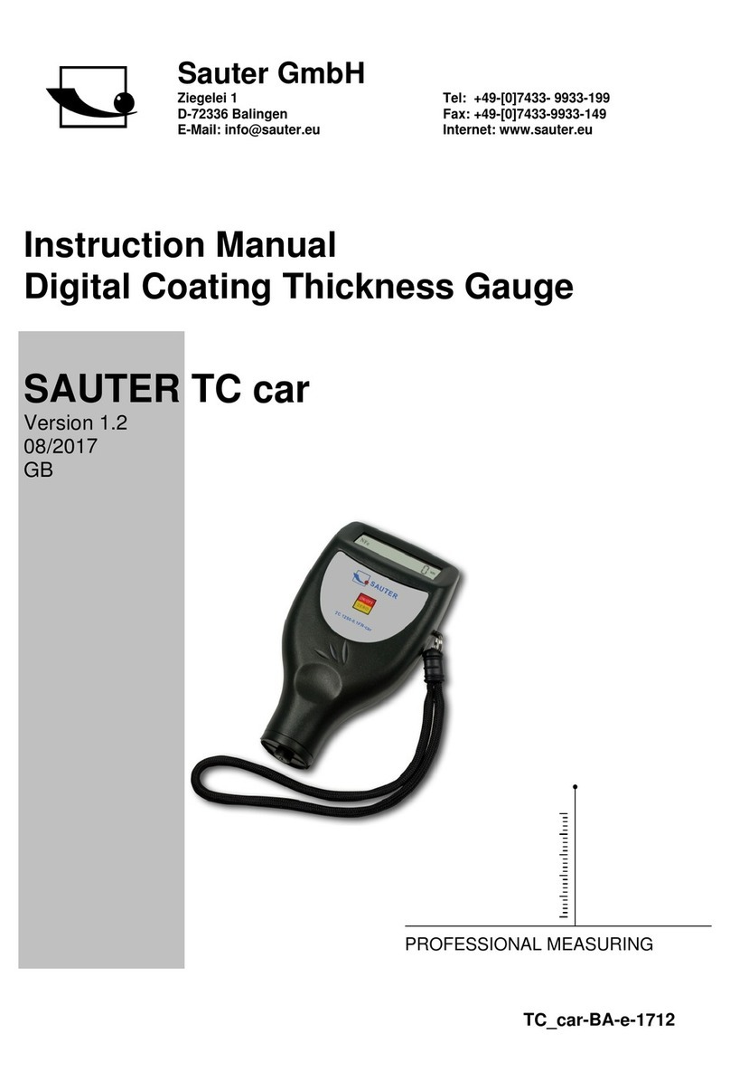
sauter TC 1250-0.1F User manual

Sauter GmbH
Ziegelei 1
D-72336 Balingen
e-mail: info@kern-sohn.com
Phone : +49-[0]7433- 9933-0
Fax: +49-[0]7433-9933-149
Internet: www.sauter.eu
Instruction Manual Digital Coating
Thickness Gauge
SAUTER TC
Version 2.0
04/2020
GB
TC-BA-e-2020
PROFESSIONAL MEASURING

2 TC-BA-e-2020
GB
SAUTER TC
V. 2.0 04/2020
Instruction Manual Digital Coating Thickness
Gauge
Thank you for purchasing a digital coating thickness gauge from SAUTER. We hope
you will be very satisfied with the high quality of this measuring device and its extensive
functionality. For any questions, wishes and suggestions please do not hesitate to
contact us.
Table of contents:
1. Introduction.................................................................................................... 3
1.1 General description.................................................................................................................. 3
2. Functions........................................................................................................ 3
3. Technical data................................................................................................ 3
4. Description of the control panel................................................................... 5
5. Measuring procedure .................................................................................... 5
6. Zero adjustment............................................................................................. 6
7. Battery replacement ...................................................................................... 6
8. Adjusting foils................................................................................................ 7
9. General notes................................................................................................. 7
10. Restore factory settings................................................................................ 7
11. Notes............................................................................................................... 8

TC-BA-e-2020 3
1. Introduction
1.1 General description
This coating thickness gauge is small, light and handy. Although it has complex and
advanced equipment, it is convenient and easy to use.
Its robustness allows it to be used for many years, provided that all instructions in this
manual are carefully followed.
Therefore please keep them always within reach!
Note: It is strongly recommended to adjust the new meter before first use, as
described in chapter 6. This will result in a higher measurement accuracy from
the beginning.
2. Functions
"This device complies with the ISO- Norm 2360 as well as the DIN-Norm, ASTM and
BS. This means that it can be used both under laboratory conditions and under rough
environmental conditions "in the field".
"The F" probe measures the thickness of non-magnetic layers, e.g. paint, plastic,
enamelled porcelain, copper, zinc, aluminium, chrome, lacquer layers etc.
These layers should be on magnetic materials such as steel, iron, nickel, etc. This
probe is often used to measure the thickness of galvanized layers, lacquer layers,
enamelled porcelain layers, phosphorescent layers, copper plates, aluminium plates,
alloys, paper, etc.
"The N- probe measures the thickness of non-magnetic layers on non-magnetic
metals.
It is used to measure anodizations, lacquer layers, glazes, colours, enamel, plastic
layers, powder coating etc. These should be on non-magnetic substrates such as
aluminium, sheet metal, non-magnetic stainless steel and others.
"The FN measuring probe is a combination of both probes and is therefore defined for
both areas of application
"Automatic recognition of the carrier material
"Manual or automatic switch-off to conserve battery power.
"Metric/ imperic conversion of the measured values of µm/mil
"Two measuring modes: - single and continuous (S= single/ C= continuous)
"Wide measuring range and high resolution
" Can be connected to a PC for data transfer via RS 232 interface
Cable and software are available as optional accessories (ATC-01).
3. Technical data
TC 1250-0.1F
TC 1250-0.1FN
TC 1250-0.1N
Display
4 digits, 10mm LCD display with backlight
Measuring range
0 to 1250 μm / 0 to 50 mil (standard)

4 TC-BA-e-2020
Resolution
0,1 µm (0 to 99,9 µm), 1 µm (over 100)
Measurement
uncertainty
3 % of the measured value or Min ± 2,5 µm.
Applies within the tolerance band of ± 100 µm
around the typical measuring range if a two-point
calibration was also performed within this
tolerance band
off-set accuracy
1 % of the measured value or min. 1,0 μm
Applies within ± 50 μm around the offset Accur
Point
PC connection
RS-232 interface
Power supply
4x1.5 AAA batteries (UM-4)
Ambient
temperature
0°C to 50°C
Air humidity
≤80%
Dimensions
126 x 65 x 27mm
Weight
Ca 81g (without batteries)
Scope of delivery
Carrying case, operating instructions
Depending on the type:
1. built-in measuring probe F: TC 1250-0.1 F, with
F/N key
2. built-in measuring probe N: TC 1250-0.1 N, with
F/N key
3. built-in measuring probe FN: TC 1250-0.1 FN,
without F/N u.S/C key
- Spacer foils, for each model
- Zero plate (aluminium) for model N
- Zero plate (iron) for model F
- 2 zero plates (aluminium and iron) for model FN
(combination unit)
Optional accessories: Software and cable RS-
232C: ATC-01
Attention: All accuracy specifications apply after adjustment!

TC-BA-e-2020 5
4. Description of the control panel
Model TC-F and TC-N Model TC-FN (Combi Model)
4-1 Measuring probe: F, N, or FN
4-2 Display
4-3 Zero key
4-4 Plus button
4-5 Minus key
4-6 On and Off button (multifunctional)
4-7 µm/ mil Changeover key (shortcut key)
4-8 Battery compartment / cover
4-9 S/C measuring mode button (single/continuous)
4-10 Connector for RS-232C connection
4-11 F/ NF- key
5. Measuring procedure
a) Switch on by pressing the on/off button 4-6. '0' appears on the display 4-2.
The TC 1250-0.1FN meter recognizes the setting of the last measurement itself by the
symbol 'Fe' (= F) for ferrous metals or 'NFe' (= N) for non-ferrous metals shown on the
display. It switches to the automatic measuring mode, which also correctly recognizes
and assigns the zero plate or any other substrate itself.
b) Place the measuring probe 4-1 on the layer to be measured. The layer thickness
can now be read on the display. The reading result can be corrected by pressing the
plus key 4-4 or the minus key 4-5. For this purpose, the measuring probe should not
be in close proximity to the layer to be measured or the zero plate.
c) To take the next measurement, simply raise the measuring probe 4-1 by more than
1cm, the display will show "0" again and step b) will be repeated.
4-10
4-2
4-5
4-3
4-4
4-1
4-4
4-5
4-6
4-8
4-9
4-8
4-7
4-7
4-10
4-2
4-11

6 TC-BA-e-2020
d) In case of possible inaccuracies in the measurement result, it is recommended to
adjust the measuring instrument before measurement, as described in chapter 6.
e) On the one hand, the device can be switched off with the on/off button 4-6.
Otherwise, it switches itself off 80 seconds after the last key is pressed.
f) The measuring unit can be displayed in µm or mil. The changeover is made as
follows:
- By pressing the changeover key 4-7 or
- the on/off key 4-6 is pressed and held until 'UNIT' is shown on the display and then
the zero key 4-3 is pressed. The measuring unit changes over to the other one when
the on/off key is released again.
This process takes a total of 7 seconds (from pressing the zero or on/off button).
g) To change to the measuring mode from 'simple' to 'continuous' or vice versa, the
zero or on/off key 4-6 must be pressed and held down until 'SC' appears in the display.
Then the zero key 4-3 ispressed. The symbol ((-)) stands for the continuous measuring
mode and 'S' for the simple measuring mode. This process takes 9 seconds (from
pressing the on/off button).
6. Zero adjustment
a) The zero adjustment for 'Fe' (=F) and 'NFe' (=N) should be done separately. The
iron zero plate is taken when 'Fe' is read on the display, while the aluminium zero plate
is taken when 'NFe' is read.
The measuring probe 4-1 is now carefully placed on the zero plate. The zero/on/off key
4-6 is pressed and '0' is shown in the display without lifting the probe.
Attention: The zero adjustment is useless if the measuring probe is not directly
on the zero plate or another, uncoated carrier material.
b) A suitable adjustment foil, which corresponds approximately to the measuring range,
must be selected.
(c) This standard alignment foil is positioned on the supplied zero plate or on the
appropriate uncoated substrate for the forthcoming tests.
d) Carefully press the measuring probe 4-1 in the middle of the standard foil and then
lift it off again. The reading on the display corresponds to the measured value of the
layer thickness.
This reading can be corrected by pressing the plus key 4-4 or the minus key 4-5. This
should be done if the probe is not in the nearer vicinity of the zero plate or the
corresponding carrier material.
e) The procedure described in d) should be repeated until the result is correct.
7. Battery replacement

TC-BA-e-2020 7
a) When the battery symbol ``+/-`` appears on the display, the batteries should be
replaced.
b) The battery cover 4-8 is removed from the meter and the batteries are removed.
c) The batteries (4x1.5 V AAA/UM-4) are inserted by observing the polarity when
inserting them.
d) If the device is not used for a longer period of time, the batteries should be removed.
8. Adjusting foils
This instrument includes an adjustment foil set with different foils and measuring
ranges, but always covers the measuring range from 20 to 2000µm. These are also
available as optional accessories, article ATB-US07
9. General notes
a) The measuring instrument should always be adjusted on the base material used for
the actual measurement, if possible, instead of on the supplied zero plate F made of
steel or N made of aluminium. This makes the measuring accuracy more accurate from
the outset.
b) The measuring probe may wear out. The lifetime of it usually depends onthe number
of measurements and the roughness of the layer to be measured. The replacement of
a measuring probe should only be carried out by qualified personnel
can be carried out.
10.Restore factory settings
a) It is recommended that the factory settings be performed in the following cases:
- no more measurements can be made at all
- the measuring accuracy is impaired due to drastic changes in the environment in
which the measuring instrument is used
- After replacing the measuring probe
(b) Procedure:
The factory settings include both the settings for "Fe" (F) and for "NFe" (N).
Please note which symbol is shown on the display.
Only one setting at a time can be made, as follows:
- Press the on/off button 4-6 and do not release it until the display shows "CAL". It
takes about 5 seconds from the start of this button operation until CAL is displayed.
The measuring probe 4-1 is carefully pressed onto the corresponding carrier material.
Then the zero key is pressed, which is accompanied by a beep.
When NF:H appears on the display, the measuring probe 4-1 is raised by more than 5
cm.
Then the zero button is pressed again and the meter returns to the measuring mode.
The factory settings are now complete.
Note: This process should always be completed within the following 6 seconds.
Otherwise, it will be automatically interrupted by the unit and the reset will be invalid.

8 TC-BA-e-2020
11.Notes
With the LN function, the linearization of the measuring instrument specified by the
calibration can be changed. However, it is strongly recommended not to make any
changes to the LN value, as this change will lead to deviating measurement results.
Any change in the Ln value can significantly affect the measuring accuracy. This
value should only be set by qualified personnel.
In general, the larger the Ln value, the smaller the reading result for the same layer
thickness. A small change of the Ln- value causes a large change in the reading
result in the upper measuring range (at 500µm/ 20mil).
Thus the Ln value is to be corrected:
Pressing the on/off button: It takes about 11 seconds from the beginning of pressing
the on/off button.
Its value can be changed by pressing the Plus or Minus key after 'LN' appears in the
display and releasing the On/Off key. The value is stored and then the zero key is
pressed.
A: The reading result in the lower area is corrected by pressing the Plus or Minus key.
B: The Ln value is increased if the reading result is correct in the lower range (e.g.
51µm) but too large in the upper range (e.g. 432µm).
In contrast, the Ln value is reduced if the reading result is correct in the lower range
(e.g. 51µm) but too small in the upper range (e.g. 432µm).
C: This procedure of A. and B. is repeated until the reading result is satisfactory in its
accuracy for each distance foil.
Note:
To view the CE declaration, please click on the following link:
https://www.kern-sohn.com/shop/de/DOWNLOADS/
This manual suits for next models
2
Table of contents
Other sauter Measuring Instrument manuals

sauter
sauter TFL611F201 User manual

sauter
sauter FK 10 User manual

sauter
sauter TU 80-0.01US User manual

sauter
sauter FT 1K User manual

sauter
sauter FH-M User manual

sauter
sauter FA User manual

sauter
sauter TB-US User manual
sauter
sauter FP Series User manual

sauter
sauter TB Series User manual

sauter
sauter FC 1K-BT User manual

sauter
sauter SP 200K User manual
sauter
sauter CT Q1 User manual

sauter
sauter TB-US User manual

sauter
sauter TB User manual

sauter
sauter TF 1250-0.1FN User manual

sauter
sauter TN-US User manual

sauter
sauter TVP-L User manual

sauter
sauter FH Series User manual
sauter
sauter TVL User manual
sauter
sauter SU User manual