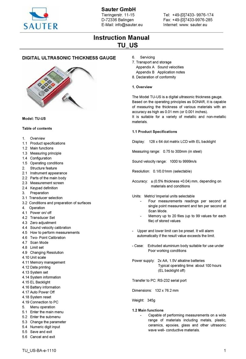
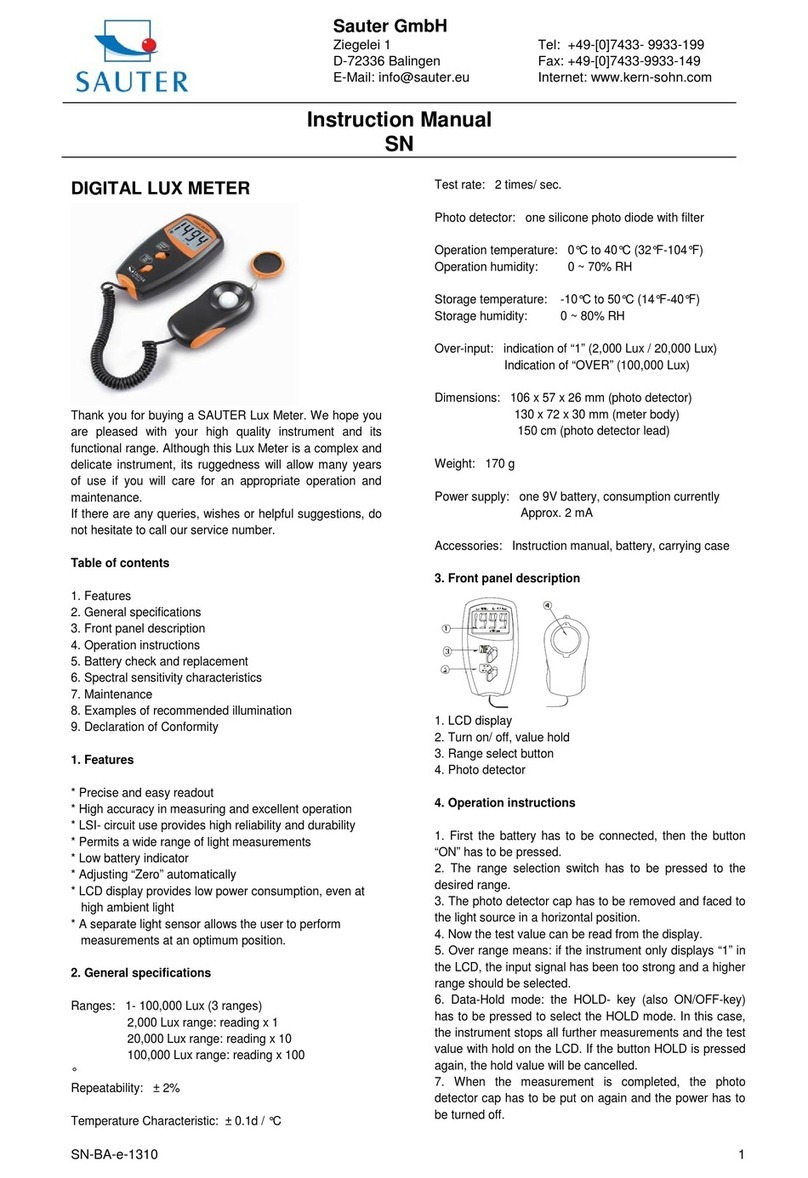
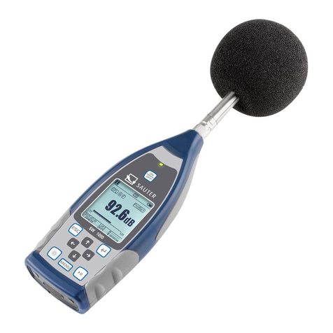
sauter TO-EE User manual

Sauter GmbH
Ziegelei 1
D-72336 Balingen
e-mail: info@kern-sohn.com
Phone : +49-[0]7433- 9933-0
Fax: +49-[0]7433-9933-149
Internet: www.sauter.eu
Instruction Manual Multimode
Ultrasonic Material Thickness Gauge
SAUTER TO
Version 2.0
04/2020
GB
TO-BA-e-2020
PROFESSIONAL MEASURING

2 TO-BA-e-2020
GB
SAUTER TO
V. 2.0 08/2020
Instruction Manual Multimode Ultrasonic Material
Thickness Gauge
Congratulations on the purchase of a multimode ultrasonic thickness gauge from
SAUTER. We wish you much pleasure with your quality measuring instrument with a
high functional range. For any questions, requests and suggestions, please contact
our customer service by telephone.
Table of contents:
1General information....................................................................................... 4
1.1 Product specification............................................................................................................... 4
1.2 Measuring principle.................................................................................................................. 4
1.3 Converters: technical data ...................................................................................................... 4
1.4 Configuration............................................................................................................................ 6
1.5 Working conditions:................................................................................................................. 6
2Keypad and display....................................................................................... 6
2.1 Main screen............................................................................................................................... 7
2.2 Control panel ............................................................................................................................ 8
3Preparation for measurement....................................................................... 8
3.1 Selection of the converter ....................................................................................................... 8
3.2 Condition and preparation of surfaces ................................................................................ 10
4Operation...................................................................................................... 11
4.1 Power supply .......................................................................................................................... 11
4.2 Connecting the probe ............................................................................................................ 11
4.3 Switching on the device (Power ON).................................................................................... 11
4.4 Configuration of the standby settings ................................................................................. 12
5Operation...................................................................................................... 13
5.1 Setting the working mode ..................................................................................................... 13
5.2 Selection of the probe............................................................................................................ 13
5.3 Function "Probe Zero............................................................................................................. 13
5.4 Calibration of the sound velocity.......................................................................................... 14
5.5 Performing measurements.................................................................................................... 17
5.6 Set View Mode ........................................................................................................................ 18
5.7 Set normal thickness ............................................................................................................. 19
5.8 Set limit value ......................................................................................................................... 20
5.9 Setting the resolution............................................................................................................. 20
5.10 Memory Management............................................................................................................. 21
5.11 Setting the key tone ............................................................................................................... 23
5.12 Set warning tone..................................................................................................................... 23
5.13 Set LCD brightness level....................................................................................................... 23
5.14 Setting the display readiness................................................................................................ 23
5.15 Setting automatic switch-off ................................................................................................. 24
5.16 Change system of units......................................................................................................... 24

TO-BA-e-2020 3
5.17 Setting the date and time....................................................................................................... 24
5.18 Set language ........................................................................................................................... 25
5.19 Product info ............................................................................................................................ 26
5.20 Reset system .......................................................................................................................... 26
5.21 USB Communication.............................................................................................................. 26
6Measurement technology............................................................................ 26
6.1 Measurement procedure........................................................................................................ 26
6.2 Wall measurement.................................................................................................................. 27
7Service.......................................................................................................... 27
8Transport and storage................................................................................. 27
9Sound velocity ............................................................................................. 28
10 Instructions for use ..................................................................................... 29
10.1 Measurement of large and small pipes ................................................................................ 29
10.2 Measurement of hot surfaces ............................................................................................... 29
10.3 Measuring of laminate materials........................................................................................... 30
10.4 Measurement through paint layers and coating ................................................................. 30
10.5 Suitability of materials........................................................................................................... 30
10.6 Coupling agents ..................................................................................................................... 31

4 TO-BA-e-2020
1 General information
The model TO-EE is an ultrasonic material thickness gauge with several operating
modes. Based on the same operating principles as SONAR, the instrument can
measure the thickness of various materials with an accuracy of down to 0.1 / 0.01
millimetres. The gauge's multi-mode function allows the user to switch between pulse-
echo mode (error and indentation detection) and echo-echo mode (determination of
the actual material thickness without the presence of any paint or coating thickness).
1.1 Product specification
•Multi mode: Pulse-echo mode (P-E mode) and echo-echo mode (E-E mode). In
the echo-echo mode, the wall thickness can be measured without taking the paint
or coating thickness into account.
•Wide measuring range: pulse-echo mode: (0.65 ~ 600) mm (in steel, depending
on the probe). Echo-Echo mode: (3 ~ 60) mm.
•V-path correction to compensate for the non-linearity of the probe.
•TFT colour display (320 × 240 TFT-LCD) with adjustable backlighting allows the
user to work at workstations with low visibility.
•Up to 100 groups of measured thickness values can be stored in the non-volatile
memory. A maximum of 100 data sets per group are permitted.
•Two AA alkaline batteries are used as power source. This ensures continuous
operation of at least 100 hours (standard setting for brightness). Energy-saving
functions "Display Standby" and "Auto Power Off" are available.
•With the internal Bluetooth module, a wireless connection with PC or other mobile
devices can be established.
•USB 1.1 port. Online transmission of measurement data via USB to PC.
1.2 Measuring principle
The ultrasonic thickness gauge determines the thickness of a part or structure by
accurately measuring the time it takes a short ultrasonic pulse generated by a
transducer to pass through the thickness of the material, reflect off the back or inner
surface and return to the transducer. The measured bi-directional travel time is divided
by two to account for the outward and return paths and is then multiplied by the speed
of sound in the respective material. The result is reflected in the following ratio:
2tv
H
=
H = thickness of the test sample
v = sound velocity in the respective material
t = measured outward and return time
1.3 Converters: technical data
Model
Freq
[MHz]
Φ
[mm]
Measuring range
[mm].
Lower limit
value [mm]
Description

TO-BA-e-2020 5
N02
2,5
14
3.0 ~ 300.0 mm
(in steel)
40 mm (in grey cast
iron HT200)
20 mm
for thick, strongly
weakening or
strongly scattering
materials
N05
5
10
1 ~ 600.0 mm
(in steel)
Φ 20 mm ×
3,0 mm
Normal
measurement
N05/90°
5
10
1 ~ 600.0 mm
(in steel)
Φ 20 mm ×
3,0 mm
Normal
measurement
N07
7
6
0.65 ~ 200.0 mm
(in steel)
Φ 15 mm ×
2,0 mm
For measurements
of thin pipe walls or
pipe walls with low
curvature
HT5
5
12
1 ~ 600.0 mm
(in steel)
30 mm
For measurement
at high
temperatures
(below 300 °C)
P5EE
5
10
P-E: 2~ 600 mm
E-E: 3 ~ 60 mm
Φ 20 mm ×
3,0 mm
Normal
measurement
and thickness
measurement via
the paint or coating
thickness

6 TO-BA-e-2020
1.4 Configuration
Standard
configuration
No.
Article
Piece.
Remarks
1
Housing
1
2
P5EE probe (5 MHz)
1
3
Coupling agent
1
4
Device packaging
1
5
Operating instructions
1
6
Alkaline battery
2
Type AA
7
USB cable
1
Optional
configuration
8
Probe N02 (2.5 MHz)
9
Probe N05/90° (5 MHz)
see table 1.1.
10
Probe N05 (5 MHz)
11
Probe N07 (7 MHz)
12
Probe HT5 (5 MHz)
1.5 Working conditions:
Operating temperature: 0 C ~ +50 C
Storage temperature: -20 C ~ +70 C
Relative humidity: ≤ 80 %
At the place of use, vibrations, strong magnetic fields, corrosive media and heavy dust
accumulation must be avoided.
2 Keypad and display
1. 2.1 Ekran główny
1 Housing
2 Record "Probe Zero"
3 Keyboard
4 TFT display
5 USB connection
6 Pulse encoder
socket
7 Receiving socket
8 Sticker
9 Serial number
10 Battery
compartment cover
11 Probe

TO-BA-e-2020 7
2.1 Main screen
Function
Declaration
Mode
"E-E" indicates that the instrument is operating in echo echo
mode; "P-E" indicates that the instrument is operating in
pulse echo mode;
Sample
Probe selection
Velocity
Sound velocity
Battery
Indicates the remaining capacity of the battery
Thickness
Last measurement result
Unit
Unit system: mm or inch
Diff value
Measurement result when working in Diff mode
Time
System time
Status
USB communication status
Operation
indicates which process is already active
Record
displays the selected data group and the number of data
records
Couple
Displays the coupling status
Nominal Thickness
Keyboard combinations

8 TO-BA-e-2020
2.2 Control panel
The design of the device allows the user
quick access to all device functions. A user-
friendly menu system allows access to any
function by pressing a few keys.
Function keys for selecting the desired
function on the display. In the following
sections of this manual they are referred to as
F1, F2 and F3, from left to right.
ON/OFF or CANCEL
Sample-Zero process
Save measurement result
Confirm/Enter
Plus or scroll up
Minus or scroll down
3 Preparation for measurement
3.1 Selection of the converter
The meter is designed to perform measurements on a wide range of materials, from
various metals to glass and plastics. However, different types of materials require the
use of different transducers. Choosing the right transducer for the application is
essential to ensure accurate and reliable measurements. The following sections
highlight the important characteristics of transducers that should be considered when
selecting a transducer for a particular application.
In general, the best transducer for a given application is a sensor that emits sufficient
ultrasonic energy into the material to be measured so that a strong, stable echo is
received by the instrument. The strength of the ultrasound during propagation can be
influenced by several factors. These are listed below:
•Initial signal strength: The stronger the signal is at the beginning, the stronger
its back echo. The initial signal strength is largely determined by the size of the
ultrasonic transmitter in the transducer. A large emitting area emits more energy
into the material to be measured than a small emitting area. Therefore, a so-
called "1/2 inch" transducer emits a stronger signal than a "1/4 inch" transducer.

TO-BA-e-2020 9
•Absorption and scattering: If the ultrasound propagates through any material, it
is partially absorbed. If the material through which the sound propagates has a
grain structure, the sound waves are scattered. These two effects reduce the
strength of the waves and thus the ability of the instrument to detect the
returning echo. The ultrasonic sound with higher frequency is absorbed and
scattered more than the ultrasonic sound with lower frequency. Although it
seems advisable to use a lower frequency transducer in all cases, low
frequencies are less directional than high frequencies. Therefore, a higher
frequency transducer is the better choice for determining the exact position of
small indentations or flaws in the material to be measured.
•Transducer geometry: The physical boundary conditions of the measurement
environment sometimes determine the suitability of a transducer for a specific
measurement task. Some transducers may simply be too large to be used in
space limited areas. In addition, the contact area available for contacting the
transducer may be limited, which requires the use of a transducer with a small
contact area. Measuring on a curved surface, such as an engine cylinder wall,
may require the use of a transducer with a suitably curved contact area.
•Temperature of the material: When measuring on very hot surfaces, high
temperature transducers must be used. These transducers are manufactured
using special materials and techniques that allow them to withstand high
temperatures without damage. In addition, care must be taken when using a
high temperature transducer to perform "Sensor Zeroing" or "Calibration to
Known Thickness".
The choice of the appropriate converter is often a question of compromise between
different properties. It may be necessary to test different transducers in order to find a
suitable sensor for the respective application.
The converter is the "working tool" of the device. It transmits and receives ultrasonic
waves with which the instrument calculates the thickness of the material to be
measured. The transducer is connected to the instrument via the cable supplied and
two coaxial connectors. When using transducers, the arrangement of the double
coaxial connectors is irrelevant: each connector can be connected to any of the two
jacks on the instrument.
The transducer must be used correctly in order to obtain an accurate and reliable
measurement result. Below is a brief description of the transducer, followed by its
operating instructions.

10 TO-BA-e-2020
The left figure shows a typical transducer from below. The two semicircles of the
contact surface are visible, as is the barrier separating them. One of the semicircles is
responsible for propagating ultrasound in the material to be measured and the other
semicircle is responsible for returning the echo to the transducer.When the transducer
is in contact with the material to be measured, the area just below the centre of the
contact surface is measured.
The right figure shows a top viewof a typical transducer. Press the transducer upwards
with thumb or index finger to fix the transducer in place. Moderate pressure is sufficient
as the transducer only needs to be held immobile and the contact surface must beflat
against the contact surface of the material to be measured.
3.2 Condition and preparation of surfaces
In any ultrasonic measurement scenario, the shape and roughness of the
measurement surface are of utmost importance. Rough, uneven surfaces can restrict
the propagation of ultrasound through the material and lead to unstable and therefore
unreliable measurements. The surface to be measured should be clean and free of
small particles, rust or scale. The presence of such obstacles prevents the transducer
from contacting the contact surface correctly. Often a wire brush or scraper will help to
clean the surface. In extreme cases, rotary grinders or grinding wheels can be used.
However, care must be taken to avoid surface cracks that prevent proper coupling of
the transducer.
Extremely rough surfaces, such as the siliceous surface of some cast iron, are the
most difficult to measure. Such surfaces act on the sound beam like frosted glass on
light, the beam is diffused and dispersed in all directions.
Rough surfaces are not only an obstacle to measurement, but also contribute to
excessive wear of the transducer, especially in situations where the transducer
"scrubs" along the surface. Transducers should be checked regularly for signs of
uneven wear of the contact surface. If the contact surface is worn more on one side
than the other, the sound beam passing through the specimen may no longer be
perpendicular to the material surface. In this case, it is difficult to locate the smallest
irregularities in the material to be measured precisely, since the focus of the sound
beam is no longer directly below the transducer.

TO-BA-e-2020 11
4 Operation
4.1 Power supply
Two AA alkaline batteries are required as power supply. The battery compartment is
located at the rear. The cover is fixed with two screws. To insert the batteries:
➢Loosen the two screws of the battery cover.
➢Lift the cover upwards.
➢Insert the batteries into the battery compartment.
➢Close the battery compartment and tighten the screws.
➢Turn on the power to ensure that the batteries are inserted correctly and securely.
4.2 Connection of the probe
To prepare the instrument for operation, you must connect a probe to it. The instrument
is equipped with the Lemo sockets.
When connecting a probe to the instrument, it is not only important that a physical
connection is properly established. It is also important that the instrument is properly
configured to work with the installed probe.
4.3 Switching on the device (Power ON)
To start the unit, press the key until the display is activated.While the unit is starting
a start-up screen, the display shows the serial number of the unit, the installed software
version, the date and time of the system.
The initial screen of the machine appears as shown in the following figure:
Press the F1 key to switch to another language.
Press the F3 key to skip the boot check procedure and immediately switch to the
measuring mode.
The instrument carries out a self-test and then automatically switches to the measuring
mode if no further key is pressed.
The instrument is now ready for the first measurement.
The device automatically reloads the last settings. It has a special memory in which all
settings are retained even when the power supply is switched off.

12 TO-BA-e-2020
To turn off the instrument, press and hold the button until the shutdown message
appears.
The meter also has an automatic power-off function to save battery capacity. If there
is no operation for a certain period of time (set as automatic power-off delay), the meter
will automatically turn off.
Note: the device switches off automatically if the battery capacity is too low.
4.4 Configuration of the standby settings
To save battery power, the device supports the following power supply modes:
Run state - The unit operates at full frequency
Standby state - After 5 seconds (default setting), the LCD brightness is set to a low
level and the CPU operates at a lower frequency. This has no effect on the data or
memory. Pressing any button or taking a measurement will return the unit to the
operating mode and reset the default brightness.
Power off state - After 2 minutes (default setting), the unit will go from standby mode
to power off mode. The unitand displayare off and consume very little power. Pressing
any key will prevent the unit from entering the power off state with a message "Idle
Timeout! (period of inactivity expired!) is displayed and the operating mode is restored.
Switching from operating mode to standby mode is done according to the standby
delay setting of the display. The time delay can be configured by the user in the Display
Standby Delay dialog box. The unit can be reset from standby mode to operating mode
by any user activity.

TO-BA-e-2020 13
5 Operation
5.1 Setting the working mode
Users and inspectors often deal with coated materials such as pipes and tanks on site.
Typically, inspectors must remove the paint or coating prior to measurement or take
into account a certain number of defects caused by paint or coating thickness or speed.
The error can be eliminated with this meter by using a special echo-echo mode
designed for measurements in such cases. The gauge is equipped with this user-
friendly feature, so there is no need to remove the paint or coating.
To switch between P-E mode and E-E mode, press [Test Settings] in the Test Settings
dialog box.
5.2 Probe selection
Make sure that you have set the correct probe model in the device. Otherwise, the
measurement may be incorrect. In the Probe Model dialog box, use the and keys
to scroll to the currently used probe model.
Then press the or F3 key to confirm the selection. Press to cancel the operation
and exit the dialog box.
5.3 Function "Probe Zero"
The key is used to zero the instrument in the same way as a mechanical micrometer
is zeroed. If the gauge is not set to zero correctly, some error may occur in all
measurements taken with the gauge. When the Meter is zeroed, this fixed error value
is measured and automatically corrected in all subsequent measurements. Zeroing the
instrument can be done in the following ways:
1. Connect the converter to the device. Make sure that the connectors are fully
engaged. Make sure that the wear surface of the converter is clean and free of
any foreign matter.
2. Press the button to activate the Probe Zero mode (see figure below).
3. Apply a single drop of the coupling agent to the surface of the metal plate of the
probe.

14 TO-BA-e-2020
4. Press the transducer against the probe plate and make sure that the transducer
is flat against the surface.
5. Whenthe progress bar is complete, remove the transducer from the probe plate.
Repeat this procedure four times if necessary.
6. At this point the internal error factor is successfully calculated by the instrument
and compensated for in all subsequent measurements. When performing the
"Probe Zero" function, the instrument always uses the sound velocity value of
the built-in probe plate, even if a different velocity value was entered for the
actual measurements. Although the instrument remembers the last zero setting,
it is generally advisable to perform the "Probe Zero" function when the
instrument is turned on and when using another transducer. This will ensure
that the instrument is always zeroed correctly.
In Probe Zero mode, press to exit the Zero function and return to the measuring
mode.
5.4 Calibration of the sound velocity
In order for the measuring instrument to perform accurate measurements, it must be
set to the correct sound velocity for the material to be measured. Different types of
material have different inherent velocities. If the gauge is not set to the correct speed
of sound, all measurements made with the gauge will have a certain percentage of
error. Single point calibration is the simplest and most commonly used calibration
method that optimizes linearity over large ranges. Two-point calibration allows
greater accuracy in small ranges by calculating the zero point of the probe and the
velocity.

TO-BA-e-2020 15
Note: One or two-point calibration must be performed on a material after the removal
of paint or coating. Otherwise, it will result in a calculation of the material speed that is
different from the actual material speed of the material to be measured.
5.4.1 Calibration to known speed
Note: This procedure requires a sample of the specified material to be measured, the
exact thickness of which is known, e.g. by measuring it in a different way.
A table with common materials and their sound velocities can be found in Appendix A
to this manual.
In the Set Velocity dialog box, press the F1 / F2 and / keys to adjust the velocity
value up or down until it matches the sound velocity of the material being measured.
You can also press the button to select between the preset speeds.
5.4.2 Calibration to known thickness
Note: This procedure requires a sample of the specified material to be measured, the
exact thickness of which is known, e.g. by measuring it in a different way.
1. Perform the "Probe Zero" function with a standard 4.00 mm plate.
2. Apply the coupling agent to the test sample.
3. Press the transducer against the sample and make sure that the transducer is
flat against the surface of the sample. The display should show a certain
thickness value and the connection status indicator should be steady.
4. After you have achieved a stable measured value, remove the transducer. If the
displayed thickness differs from the value displayed during transducer coupling,
repeat the step in section 3.
5. Press the or key to display the Input Nominal Thickness dialog box. See
the figure below.
6. Press F1 / F2 and or to enter the thickness value until it matches the
thickness of the sample.
7. Press / F3 to confirm the entry. The meter exits the input field and returns to
the measuring mode. It now displays the calculated sound velocity value
determined from the entered thickness value.
The measuring instrument is now ready to measure.

16 TO-BA-e-2020
5.4.3 Two-point calibration
Note: This method requires two known thickness points on the test piece, which are
representative for the range to be measured.
1. The "Probe Zero" function must first be performed on the standard plate of the
instrument.
2. Apply the coupling agent to the test sample.
3. Press the transducer against the sample at the first / second calibration point
and ensure that the transducer is flat against the surface of the sample. The
display should show a (possibly incorrect) thickness value and the link status
indicator should be steady.
4. After you have achieved a stable measured value, remove the transducer. If the
displayed thickness differs from the value displayed during transducer coupling,
repeat the step in section 3.
5. Press the or key to display the Input Nominal Thickness dialog box. See
the figure at the right.
6. Press F1 / F2 and or to enter the thickness value until it matches the
thickness of the sample. Then press to calibrate the second point (see the
following figure):

TO-BA-e-2020 17
Figure below: Measuring the second point during two-point calibration.
7. Repeat steps 2 to 6 at the second calibration point.
8. Finally, press the / F3 key to complete the two-point calibration. The meter
is now ready to take measurements within this range.
5.5 perform measurements
When the instrument displays thickness measurements, the display shows the last
measured value stored until a new measurement is performed.
In order for the transducer to fulfil its task, there must be no air gaps between the wear
surface and the surface of the material to be measured. This is achieved by using a
"coupling liquid", which is usually called "coupling agent". This liquid is used to transmit
(couple) the ultrasonic waves from the transducer into the material and back again.
Before attempting to perform a measurement, a smallamount of coupling agent should
be applied to the surface of the material to be measured. Normally a single drop of
coupling agent is sufficient.
After applying the coupling agent, press the transducer (contact surface down) firmly
against the area to be measured. The Coupling Status Indicator should be displayed
and the display should show a numerical indication. When the unit is properly set to
"zero" and the correct sound velocity, the digit on the display will show the actual
material thickness directly below the transducer.
If the coupling status indicator does not appear or does not appear stable, or if the
digits on the displayappear irregular,first checkthat there isa sufficient coupling agent
film under the transducer and that the transducer is flat on the material. If this condition
persists, it may be necessary to select a different transducer (size or frequency) for the
material to be measured.
While the transducer is in contact with the material to be measured, the instrument
performs four measurements per second by continuously updating its display. When
the transducer is removed from the surface, the display shows the last measurement
taken, stored in memory.

18 TO-BA-e-2020
Note: When removing the transducer, a thin film of coupling agent is occasionally
drawn between the transducer and the surface. If this is the case, the measurement is
made through this film of coupling agent, resulting in a reading that is greater or less
than it should be. This effect is obvious when one thickness value is observed while
the transducer is being used and another value is observed after the transducer is
removed. In addition, measurements through very thick resist films or coatings can
result in the resist film or coating being measured rather than the actual material. It is
the sole responsibility of the user of the instrument to use the instrument correctly and
to detect such effects.
5.6 Set View Mode
Three view modes can be selected to display the measured value: Normal Mode, Scan
Mode and Diff Mode.
Normal Mode [Normal Mode]. As shown in the figure on the right, the last thickness
reading is displayed.
Scan Mode [Scan Mode]. In addition to the last thickness value measured, the
minimum and maximum thickness values are also displayed during the measurement.
By pressing , the minimum and maximum values are reset.

TO-BA-e-2020 19
Diff Mode. Both the last thickness reading and the differential thickness value are
displayed (of the absolute thickness value and the nominal thickness value).
Although the gauge is excellent for single point measurements, it is sometimes
advisable to examine a larger area and search for the point with the smallest thickness.
The gauge has a "Scan Mode" function that enables it.
In Normal Mode, the meter takes and displays ten measurements per second, which
is sufficient for single measurements. However, in Scan Mode, the Meter takes more
than ten measurements per second and displays the readings during scanning. While
the transducer is in contact with the material to be measured, the gauge tracks the
minimum and maximum values determined. The transducer can be "scrubbed" over a
surface, and all short signal interruptions are ignored.
5.7 Set normal thickness
In differential measuring mode, the nominal thickness of the test piece must be set.
The setting procedure is as follows:
Press the F1 / F2 key to move the highlighted cursor. Press the arrow keys to increase
/ decrease the values.
Press the key or the F3 key to confirm the setting.
Press key to cancel the change and exit the mode.

20 TO-BA-e-2020
5.8 Set limit value
Test results outside limits are displayed in red to alert the user. To change the limit
setting, press the F1 / F2 key to move the highlighted cursor. Press the arrow keys to
increase / decrease the values.
Press the key or the F3 key to confirm the setting. Press the key to cancel the
change and exit the mode.
5.9 Set resolution
The resolution of the display of the measuring instrument can be set within a range of
0.1 mm or 0.01 mm.
When the resolution is set to 0.01 mm, the surface of the test piece should be smooth
to obtain accurate test results. When measuring rough surfaces or coarse-grained
materials, it is recommended to use the low resolution.
Table of contents
Other sauter Measuring Instrument manuals

sauter
sauter TN-US User manual

sauter
sauter FH-S User manual

sauter
sauter FL User manual

sauter
sauter SP 200K User manual

sauter
sauter FS Series User manual

sauter
sauter HK-D User manual

sauter
sauter CP P9 User manual

sauter
sauter LA User manual

sauter
sauter CT P1 Instruction Manual

sauter
sauter SU User manual

sauter
sauter CP P1 User manual

sauter
sauter CO Y5 User manual

sauter
sauter TE 1250-0.1F User manual

sauter
sauter FC 1K-BT User manual

sauter
sauter TU-US User manual

sauter
sauter FA User manual

sauter
sauter TD GOLD 40 User manual

sauter
sauter CD P2 Instruction Manual

sauter
sauter TF 1250-0.1FN User manual

sauter
sauter SN User manual