Echo Wireless Dimmers 3 of 4 Copyright © 2018 Savant Systems, LLC
009-1757-02 | 190603
Echo Wireless Dimmers 2 of 4 Copyright © 2018 Savant Systems, LLC
009-1757-02 | 190603
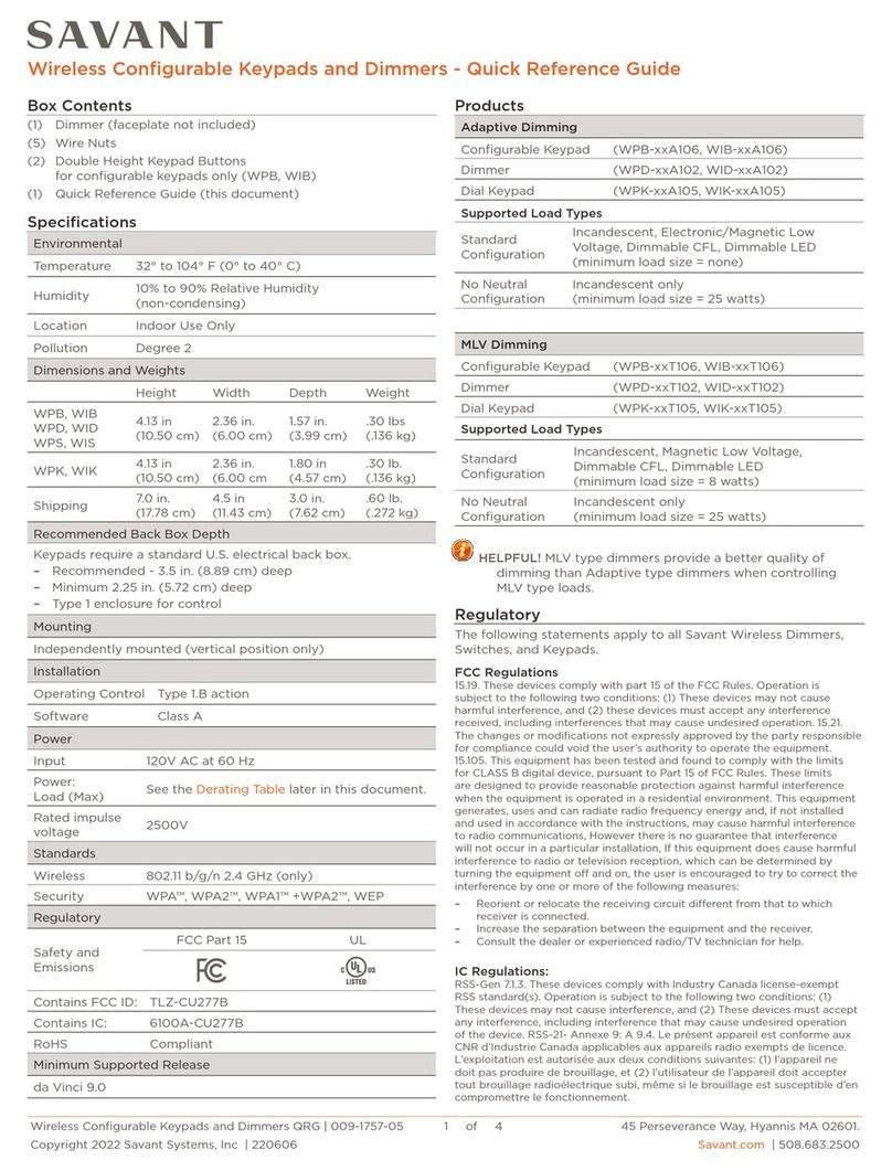
Hardware Overview
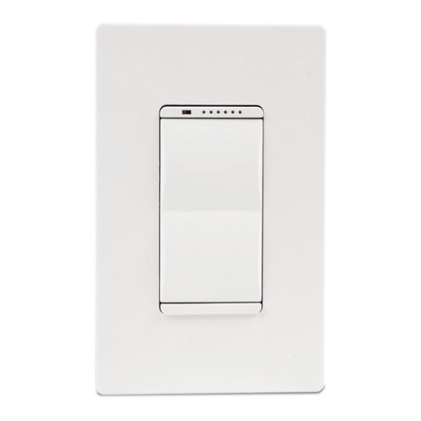
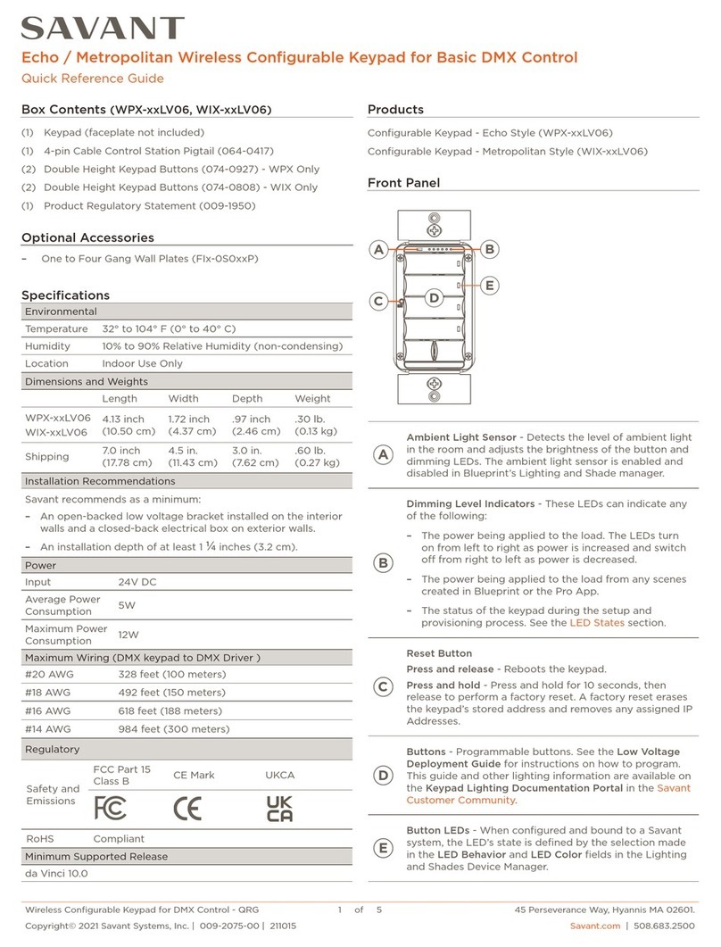
Front Panel
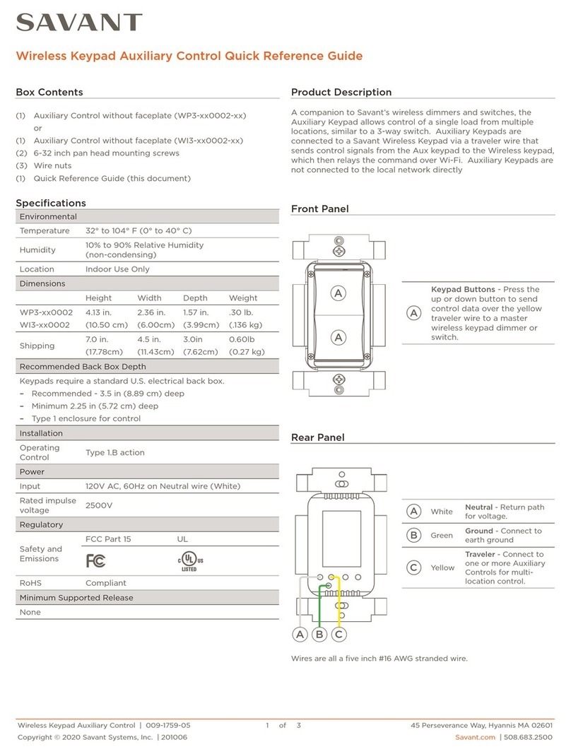
Rear Panel
AAmbient Light Sensor - Detects the level of ambient light in the room and adjusts the LED brightness on the front panel. The
ambient light sensor operation is modified using RacePoint Blueprint®.
B
Dimming Level - Six indicator LEDs track the brightness of the load. LEDs turn on from left to right as intensity on load
increases and turns o from right to left as intensity decreases. Once configured in Blueprint, the LEDs track the brightness of
the scene created.
C
Reset Button - The reset button has two functions:
–Press and release the reset button. After button is released, all LEDs on the front panel will cycle through red, green, blue
and white. Pressing the reset button causes the adaptive dimmer to test the load characteristics and determine the best
phase for the attached load. It is also used to determine the control parameters for the no neutral operation. After the reset
operation tests these parameters, the dimmer then reboots. After the reboot, the LED sequencing displayed on the main
button is determined by whether the device had previously been connected to a network. Refer to LED Sequencing table.
NOTE: The reset button should always be pressed after the Echo device is installed.
–Press and hold the reset button for five-seconds until all LEDs on the front panel illuminate. The LEDs will remain on for
two-seconds and then flash twice. The dimmer then reboots and reverts to Provisioning Mode. In Provisioning mode, the
LEDs on the main button now flash in an alternating pattern waiting to be provisioned. Refer to the LED Sequencing table.
DSwitch LED - LED lights when button is pressed. LEDs are also used to indicate the state of the switch when connecting
switch to a network. Refer to the LED Sequencing table. Once configured in Blueprint, the Switch LED shows the scene state.
EService Switch - The service switch disconnects power from the load (red wire). Toggle the service switch to O whenever
changing the load. The service switch can also be used to power cycle the dimmer.
AYellow Traveler - Wire to one or more Auxiliary Controls for multi-location control.
Green Ground - Wire to Gnd.
White Neutral - Return path for voltage.
Black Line - Wire to hot from AC power source.
Red Load -Wire to the load.
AB
CD
E
A B
C
E
A
B
C
D
E
WPB-xxx106 WPD-xxx102 WPK-xxx105
Device wires are all a five inch #16 AWG stranded wire.
EDC
BA
Electrician Removal/Installation
ELECTRIC SHOCK! The 120V AC, 60 Hz source power poses an electrical shock hazard that has the potential to cause serious
injury to installers and end users.
IMPORTANT NOTES!
–A licensed electrician is required to install any of the Echo wireless lighting devices. Isolate and turn o power at the main
breaker panel prior to installing any electrical devices.
–For supply, neutral, and ground connections use only #14 AWG or larger solid copper wires (80°C) with insulation stripped
to ⅝ in (16 mm).
1. At the main breaker panel, switch the breaker that supplies power to the dimmer or switch being replaced to O.
2. Unscrew the wall plate and remove. Verify power is removed using a 120V AC tester.
3. Unscrew the two 6-32 flat head screws and remove the existing toggle/rocker switch or analog dimmer.
4. Disconnect wires from the existing device and remove the device. It is good practice to label each wire as it is removed. If not
already identified, mark each wire to ensure proper rewiring. Especially if the circuit employs a 3-way configuration.
5. Connect the in-wall wires to the leads coming from the Echo wireless dimmer or switch using the supplied wire nuts or approved
alternative. Refer to the Wiring Diagrams and Rear View Descriptions sections for more information.
6. Insert the dimmer or switch into the electrical switch box and secure using the 6-32 flat head screws provided. DO NOT use a
powered screw driver. A powered screw driver can over tighten the screws.
7. Install front faceplate wall plate adapter. 8. From the main breaker panel, switch the breaker that supplies
power to the dimmer or switch to On.
9. Press the reset button on the front panel with the load attached.
This will calibrate the dimmer to the type of load installed.
10. Once the dimmer has calibrated itself to the load, it will go into a
quick diagnostic and the LEDs will cycle as follows:
–All LEDs will cycle through red, green, blue, and white.
–Next, the LEDs on the main button will blink several times in
sync.
–From there, the same LEDs on the main button will blink. Refer
to the LED Sequencing table.
NOTE: Install the wall adapter to cover the metal yoke prior to
applying power. If replacing an Echo style device, remove
power before removing the wall plate adapter.
NOTE: Pressing any button on the front panel after the blinking has stopped will begin a new cycle period.
11. To test without connecting to a local network, press and hold the dimmer button in the On (up) position. The load will increase
in intensity to full brightness. Press and hold the dimmer button in the O (down) position and load will decrease.
Three dimming LEDs
alternate red left to right
.5s
.5s
Keypad is in AP Mode and needs to be provisioned. After a short time (up to one minute), the
blinking will stop. In this state, the keypad is still in AP Mode. The blinking stopped intentionally
for cases where the device is not provisioned onto the network and can be used as a manual
control till provisioned.
Three dimming LEDs on the
left are solid magenta and the
three dimming LEDs on the
right blink magenta
.5s
.5s
Keypad is connected to the local network (IP Address assigned) but not bound to the Host/
Controller. After a short time (up to one minute), the blinking will stop. Although the blinking has
stopped, the keypad remains in this state until the binding process is complete.
All Dimming LEDs blink
.5s
.5s
Repeat
Indicates the type of load connected is not supported. Try toggling service switch to recalibrate.
NOTE: Once the keypad is connected to a system the color may change.
Right most dimming LED
blinks green
.5s
.5s
Boot loader mode the Keypad is ready/receiving an update.
LED Sequencing
Adapter
Electrical
Switch Box
Mounting
Screws Wall Plate and Adapter
sold separately
