432
1
-
1 +
-
2 +
WIRING AND CONNECTIONS
SPEAKER CONNECTIONS
Speaker wiring connections are made
using 4-pin Speaker Connectors
supplied with the device. The wire
slips into the hole and locks with a
screw located at the top of the
connector. Speaker connectors
accept up to 12AWG speaker cable.
NOTE: Wire order shown does not represent any wiring standard.
It may be dierent than other models.
NOTE: While not shown in the diagram above, Zones 2 to 4 follow
the same wiring as Zone 1.
RS-232 CONNECTIONS
Pins 7 and 8 are only required
for CTS/RTS handshaking.
IMPORTANT: When wiring to
this port, do not connect any
wires within the cable that are not
required for communication.
NOTE: CTS/RTS handshaking is supported for flow control based on
the profile used in the configuration.
NOTE: Wire coloring is included to identify the pins used for this connection.
Colors shown do not represent any wiring standard.
NOTE: The Pro Audio 4 does not support RS-422/485.
RJ-45 TO DB9 ADAPTERS: Savant oers RJ-45 to DB9 adapters in a variety
of configurations that can be used for RS-232 control.
Refer to the RS-232 Conversion to DB9 and Pinout Application Note located
on the Savant Community for more information on RJ-45 to DB9 adapters.
IR WIRING
IR connections are made using
4-pin IR Connectors supplied with the
device. The wire slips into the hole and
locks with a screw located at the top
of the connector.
IMPORTANT: IR Wiring Precautions
Ensure that all IR emitters are within 15 feet (4.6 meters) from the
controller’s location.
Use of 3rd party blinking IR emitters with Talk Back is not recommended.
These types of emitters can draw voltage away from the IR signal that
can degrade IR performance.
NOTE: While not shown in the diagram above, IR connections 3 and 4
follow the same wiring as 1 and 2.
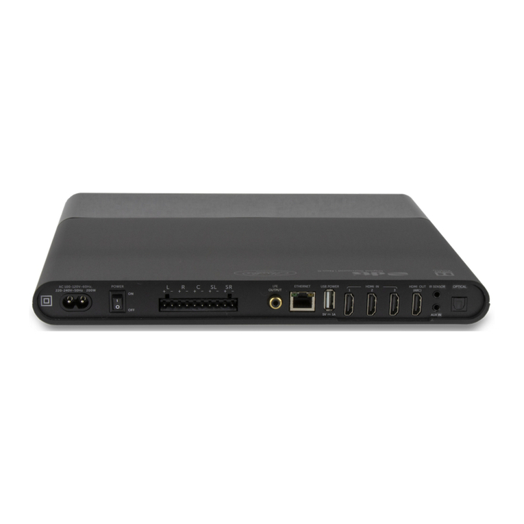
REAR PANEL
FCC INTERFERENCE STATEMENT: PRO AUDIO 4
This device complies with part 15 of the FCC Rules. Operation is subject to the following
two conditions:
1. This device may not cause harmful interference, and
2. This device must accept any interference received, including interferences that may cause
undesired operation.
The changes or modifications not expressly approved by the party responsible for
compliance could void the user’s authority to operate the equipment.
This equipment has been tested and found to comply with the limits for CLASS B digital
device, pursuant to Part 15 of FCC Rules. These limits are designed to provide reasonable
protection against harmful interference when the equipment is operated in a residential
environment. This equipment generates, uses and can radiate radio frequency energy
and, if not installed and used in accordance with the instructions, may cause harmful
interference to radio communications, However there is no guarantee that interference
will not occur in a particular installation, If this equipment does cause harmful interference
to radio or television reception, which can be determined by turning the equipment o
and on, the user is encouraged to try correct the interference by one or more of the
following measures:
–
Reorient or relocate the receiving circuit dierent from that to which receiver
is connected.
–
Increase the separation between the equipment and the receiver.
–
Consult the dealer or experienced radio/TV technician for help.
INDUSTRY CANADA STATEMENT: PRO AUDIO 4
This device complies with Industry Canada license-exempt RSS standard(s). Operation
is subject to the following two conditions:
1. This device may not cause interference, and
2. This device must accept any interference, including interference that may cause undesired
operation of the device.
Le présent appareil est conforme aux CNR d’Industrie Canada applicables aux appareils
radio exempts de licence. L’exploitation est autorisée aux deux conditions suivantes:
1. l’appareil ne doit pas produire de brouillage, et
2. l’utilisateur de l’appareil doit accepter tout brouillage radioélectrique subi, même si le
brouillage est susceptible d’en compromettre le fonctionnement.
For product
information:
Part # HDH6C001010 3B
© 2016 Savant Systems, LLC. 45 Perseverance Way, Hyannis, MA 02601
Telephone: 508 683 2500
Printed in China.
SMA-5000-00, 009-1411-01_00, 161003
savant.com
PIN 1 Right
-
PIN 2 Right +
PIN 3 Left
-
PIN 4 Left +
Use white stripe
for positive (+)
PIN 1 IR 1
-
PIN 2 IR 1 +
PIN 3 IR 2
-
PIN 4 IR 2 +
Use white stripe
for positive (+)
PIN 1 –
PIN 2 –
PIN 3 –
PIN 4 GND (RS-232)
PIN 5 RXD (RS-232)
PIN 6 TXD (RS-232)
PIN 7 CTS (RS-232)
PIN 8 RTS (RS-232)
RJ-45 CONNECTOR
(Gold pins facing up)
PIN 1 PIN 8
REGULATORY STATEMENTS
Speaker
Connections
(4) Speaker output zones
Uses 4-pin Speaker Connectors
NOTE: Compatible with 8 ohm or 4 ohm speakers.
Analog Preamp
Output
(1) Analog stereo line output (Left & Right)
Analog Inputs (2) Analog stereo inputs, RCA line-level inputs;
22 kΩinput impedance
Digital Audio
Out
(1) Digital optical preamp output (TOSLINK),
line-level 96kHz/24-bit output, fixed volume
Digital Audio In (2) Digital optical audio inputs (TOSLINK).
Supports up to 96kHz/24-bit digital audio in;
PCM stereo format only.
IR (4) IR Ports
Uses 4-pin IR Connectors to send IR signals to control
devices with an IR input or IR receiver via an IR flasher
(5V tolerant only). See IR Wiring section for important
precautions regarding IR functionality before making
any connections.
RS-232 8-pin RJ-45 port used to transmit and receive serial
binary data to and from serial controllable devices.
CTS/RTS handshaking availability based on
component profile. See RS-232 Connections section
for pin-outs.
Ethernet 8-pin RJ-45 port
10/100/1000 Base-T auto-negotiating port with Link/
Activity LEDs
Supports Audio Video Bridging (AVB)
Ethernet
Activity LED
Green Blinking: Activity (Rx/Tx)
O: No Activity
Ethernet Link
LED
Green Solid: Ethernet Link is established (any speed)
O: Ethernet link is not established
USB USB 2.0 Type A (reserved for future use)
Fuse 250V 3A slow blow fuse; field replaceable
See Pro Audio 4 Deployment Guide for additional
information on replacing the fuse.
Power Input 100/240V AC (50/60 Hz) 2.7A
I/O (power
switch)
I (On): Powers On the controller
O (O): Powers O the controller
EXPANSION
Up to three Pro Audio 4 units can be connected using AVB compliant
switching, providing up to 18 zones of distributed audio (12 amplified
zones and 6 preamp zones). See Pro Audio 4 Deployment Guide for
additional information.
NETWORK REQUIREMENTS
Connect all Savant devices to the same local area network (LAN) or subnet
as the host. Savant recommends not implementing any type of trac or
packet shaping in your network topology for the Savant devices as this may
interfere with performance.
NETWORK CONFIGURATION
To ensure that the IP Address will not change due to a power outage,
a static IP Address or DHCP reservation should be configured. Savant
recommends using DHCP reservation within the router. By using this
method, static IP Addresses for all devices can be managed from a single
UI, avoiding the need to access devices individually.
Setting DHCP reservation varies from router to router. Refer to the
documentation for the router to configure DHCP reservation.
Refer to the Pro Audio 4 Deployment Guide (009-1413-xx) located on the
Savant Community for more information.
C
D
H
K
L
M
N
I
J
F
G
A
B
E
B D HKMF
CLNI JG
AE
-
R +
-
L +
Zone 1
432
1
