Sawyer Manufacturing Company
7799 S. Regency Dr., Tulsa, OK 74131 USA
F 918.834.0318
info@sawyermfg.com
We appreciate your business!
Congratulaons on your new SAWYER product. We are proud to
have you as our customer and will strive to provide you with the best
service and reliability in the industry. This product is backed by our
extensive warranty and world-wide service network. To locate your
nearest distributor or service agency, please contact us at the phone
number and address listed on the boom of each page.
You are in good company!
Sawyer Manufacturing Company is the world leader in the design
and manufacture of pipeline and welding equipment and has been
since 1948. Sawyer equipment has become a standard in the industry
and connues to set the benchmark for quality and durability.
This user operaon manual has been made to instruct you for the best
use and operaon of your Sawyer product. Your sasfacon with our
products is our main goal. Please read this enre manual carefully,
nong all ps, notes and warnings. Safety always comes rst.
About Us
Warranty
All products manufactured by or for Sawyer Manufacturing Company are
guaranteed against defects due to faulty workmanship or materials for twelve
months from the date of purchase.
This guarantee is limited to the repair or replacement of any parts found to be
defecve, and no other liability–expressed, implied, or conngent–is assumed.
Record the following informaon for warranty purposes:
Where purchased:________________________________________________
Purchase date:___________________________________________________
Equipment Serial #:_______________________________________________
P 918.834.2550
sawyermfg.com
V1.2
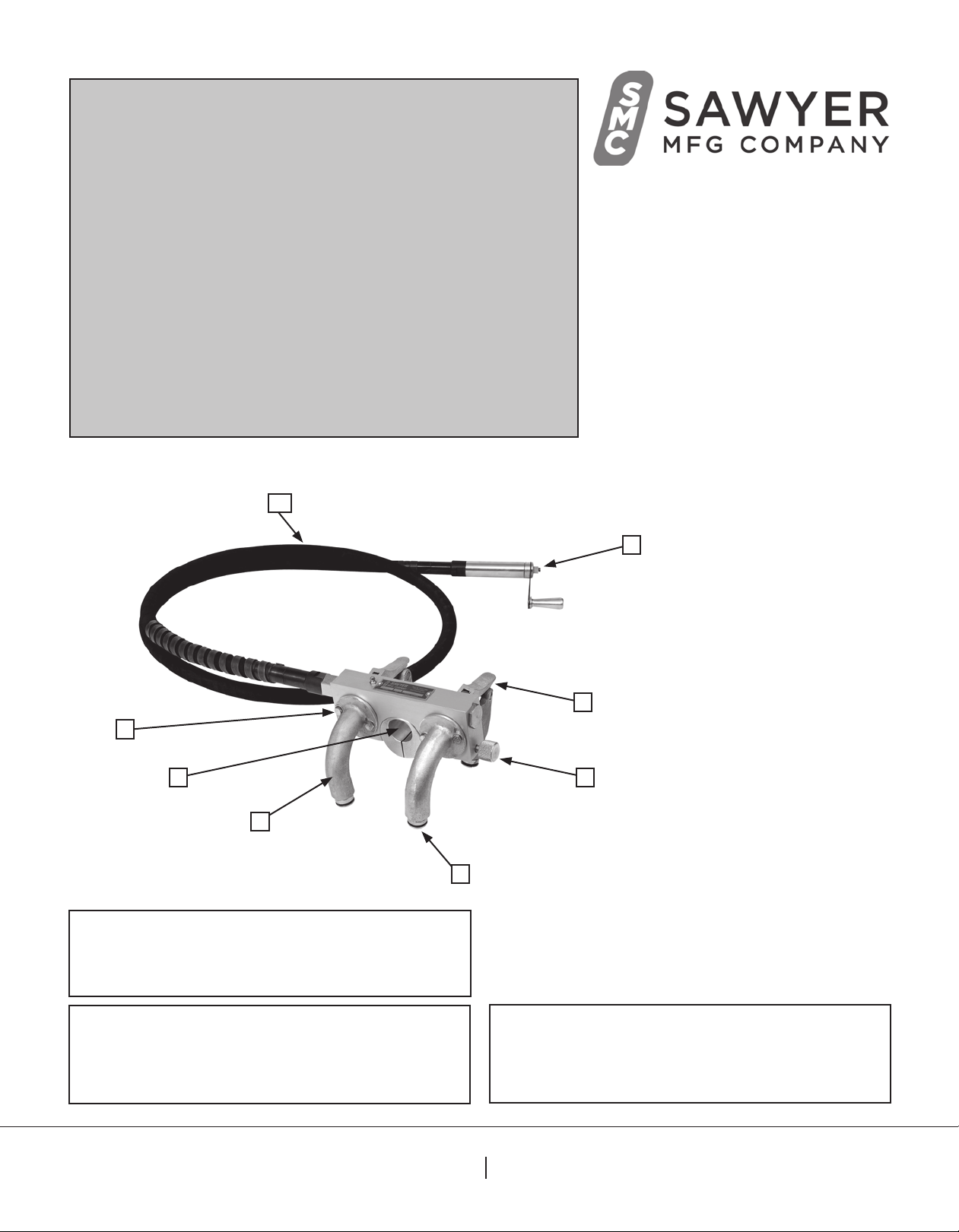
B
C
DE
G
H
F
A
A. Whip
B. Crank Handle
C. Latch Handle
D. Set Screw Assembly
E. Torch Holder
F. Drive Wheels
G. 7/16” Cap Screws
H. Legs
Beveling Band
Crawler Manual
Model 206A
Parts Diagram


