SAYSU SE Series User manual

Installation Instructions
Installation Instructions Installation Instructions
Installation Instructions SE
SESE
SE-
--
-Serie
SerieSerie
Series
ss
s
1
SE 01-Twister
SE 02-Twister & Stepper
SE 03-Bike & Trapezius
SE 04-Jump Tower
SE 05-Arm Rotation
SE 06-Ba ance Seat
SE 07-Track Tracer
SE 08-Roman Chair & Hyperextension
SE 09-Doub e Airwa ker
SE 10-Airwa ker System
SE 11-One Arm Rotation
SAYSU GmbH
Outdoor Fitness Equipment
Weitzesweg 16 A
61118 Bad Vi be / Germany
Te .: 0049 (0) 6101 802 707 - 0
Fax: 0049 (0) 6101 802 707 - 30
E-Mai : info@saysu.de
Web: www.saysu.de

Installation Instructions
Installation Instructions Installation Instructions
Installation Instructions SE
SESE
SE-
--
-Serie
SerieSerie
Series
ss
s
2
Underground
Before the insta ation you have to decide on which underground the equipment wi be insta ed. Possib e
undergrounds are (more precise y defined in DIN 1176-1.2008; tab e F.1):
•Concrete/stone
•Bitumen
•Top soi
•awn
•shock absorbing underground according to DIN EN 1177
•Loose materia only for equipment with longer posts (on request):
oSand
oGrave
oMu ch
oWood chips
According to DIN 1176-1 tab e F.1
*Upon request we can manufacture adjusted equipment for use with oose materia , we advise against the
use of sand or coarse grave
** drop height <0,6m when underground insta ation; drop height >1m when above-ground insta ation
Unit Drop
height
Concrete/
stone/
bitumen
Top soil/ lawn
Shock
absorbing
un ergroun
(accor ing to
rop height)
Loose
material*
SE 01-Twister <0,6m
(<1,0m)**
On y when
underground
insta ation
+ + -
SE 02
-
Twister &
Stepper <0,6m + + + -
SE 03-Bike & Trapezius <1,0m - + + -
SE 04-Jump Tower <0,6m + + +
We advise
against using
sand
SE 05-Arm Rotation <0,6m + + + -
SE 06-Ba ance Seat <0,6m + + + -
SE 07-Track Tracer <0,6m + + + -
SE 08
-
Roman Chair &
Hyperextension <0,6m + + + -
SE 09-Doub e Airwa ker <0,6m + + + -
SE 10-Airwa ker <0,6m + + + -
SE 11
-
One Arm
Rotation <0,6m + + + -

Installation Instructions
Installation Instructions Installation Instructions
Installation Instructions SE
SESE
SE-
--
-Serie
SerieSerie
Series
ss
s
3
Un er-groun installation with loose material
If you use oose materia ike sand, grave , mu ch or wood chips, then you have to bui t the foundation
200mm be ow ground eve and beve the foundation around the mounting p ate (see page 4). After
insta ation, the anchoring wi be fi ed up to ground eve with the fi ing materia . Then on y the main
co umn of the equipment rises out of the ground. The top ends of the screws have to be carried out in
comp iance with DIN EN 1176-1:2008 (D) 4.2.5.
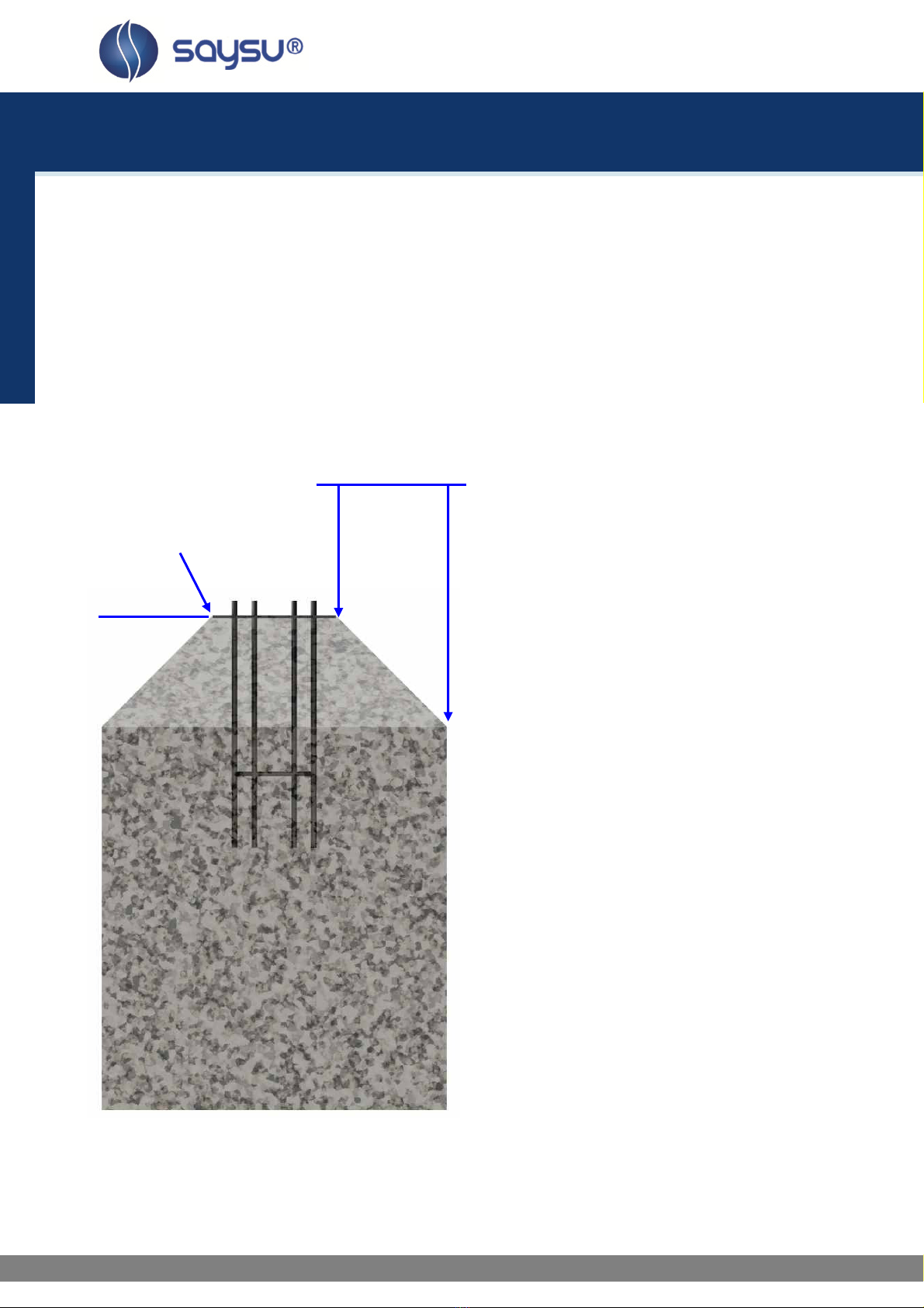
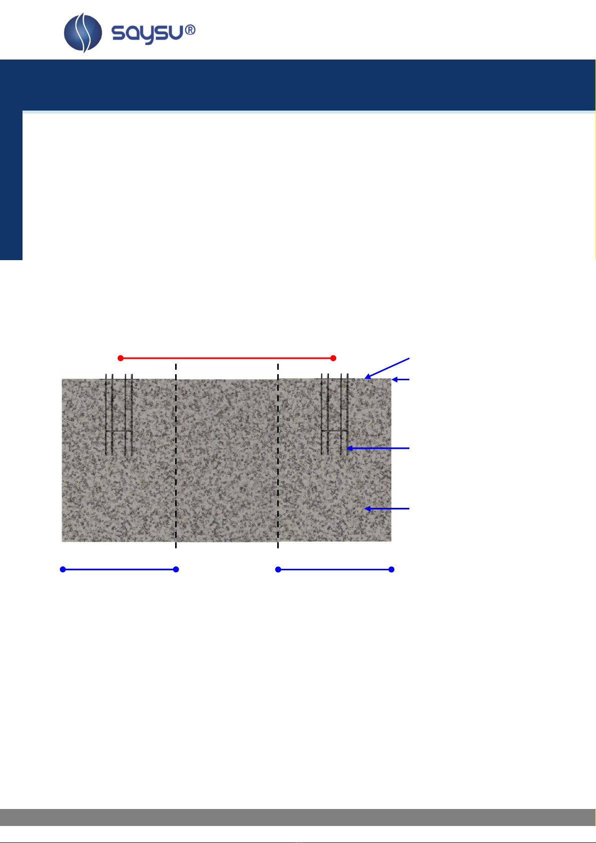
Un er-groun installation with other un ergroun
For underground insta ation the foundation is created 60mm be ow ground eve and the anchoring wi be
fi ed up to the ground eve (see mark on main co umn) with the fi ing materia . Then on y the main co umn
of the equipment rises out of the ground. The top ends of the screws have to be carried out in comp iance
with DIN EN 1176-1:2008 (D) 4.2.5.
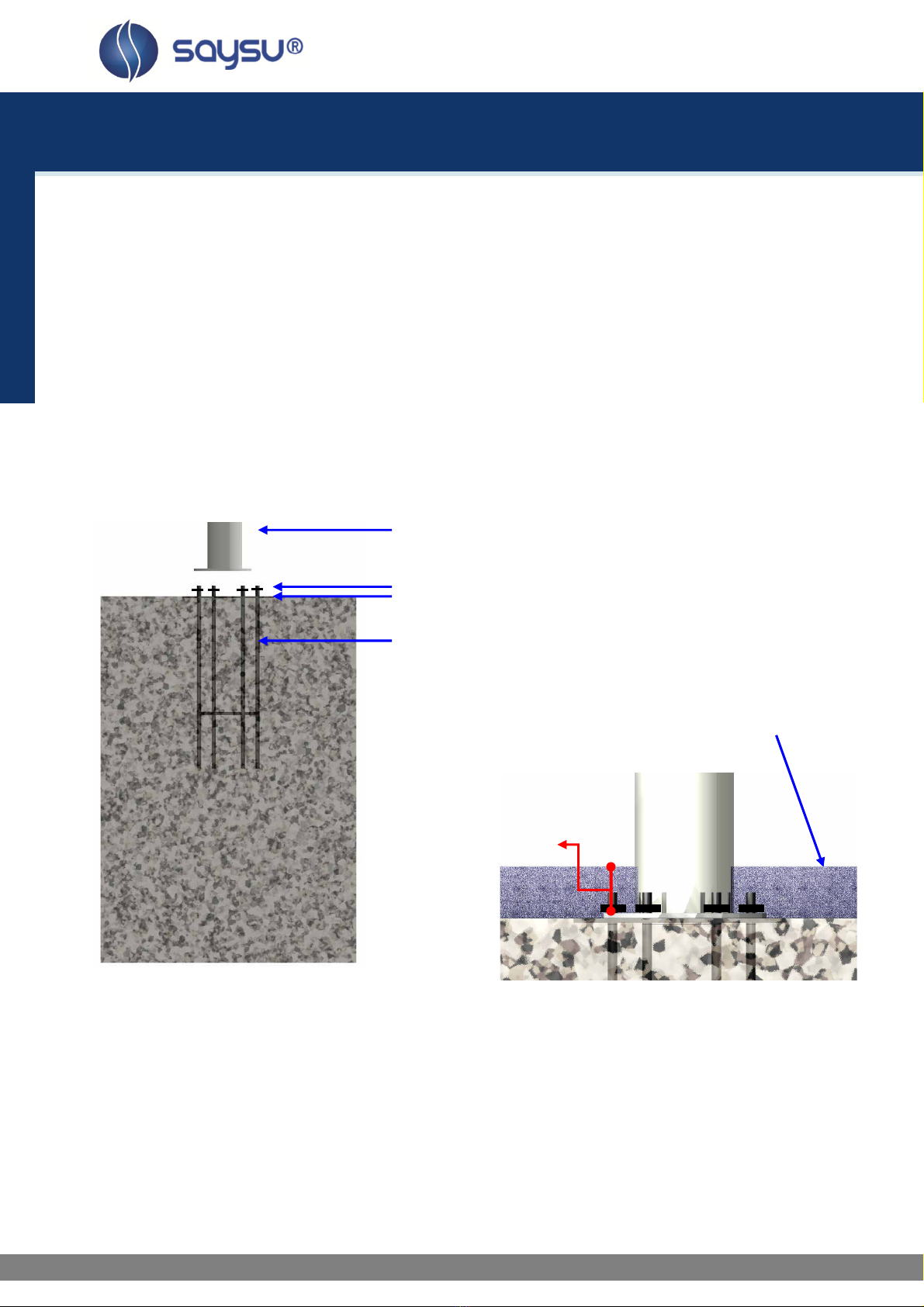
Above-groun installation
Not possib e when using oose materia . For above-ground insta ation the foundation is created at ground
eve . In this case the anchoring shou d be covered with the p astic foundation covering (soon avai ab e!).
The top ends of the screws have to be carried out in comp iance with DIN EN 1176-1:2008 (D) 4.2.5.
Concrete, stone or bitumen undergrounds are NOT icit with units that have a drop height of >60cm (see
DIN EN 1176-1). This concerns the units SE 01-Twister and SE 03-Bike & Trapezius.
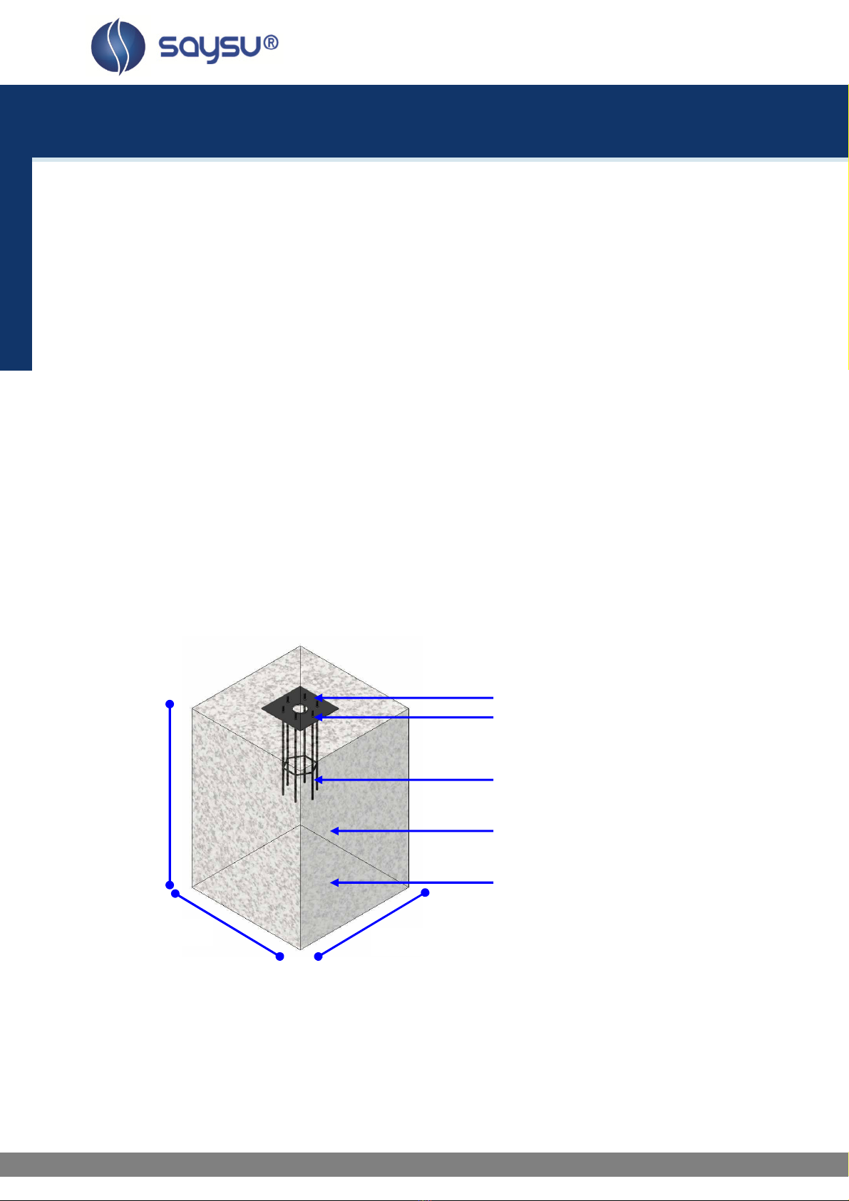
Foundation system 1 or 2
The fo owing overview shows you, which of the foundation system is used for which units:
units SE 01- 03, SE 05-06, SE 08-09, SE 11: foundation system 1 … continue on page 5
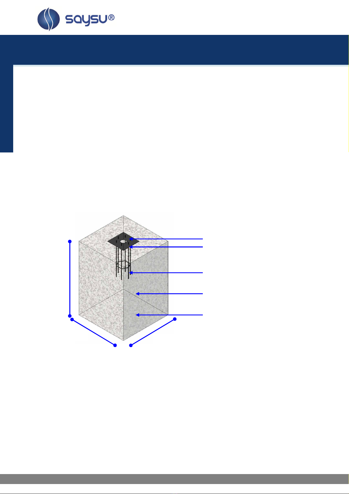
unit SE 04: foundation system 2 … continue on page 6
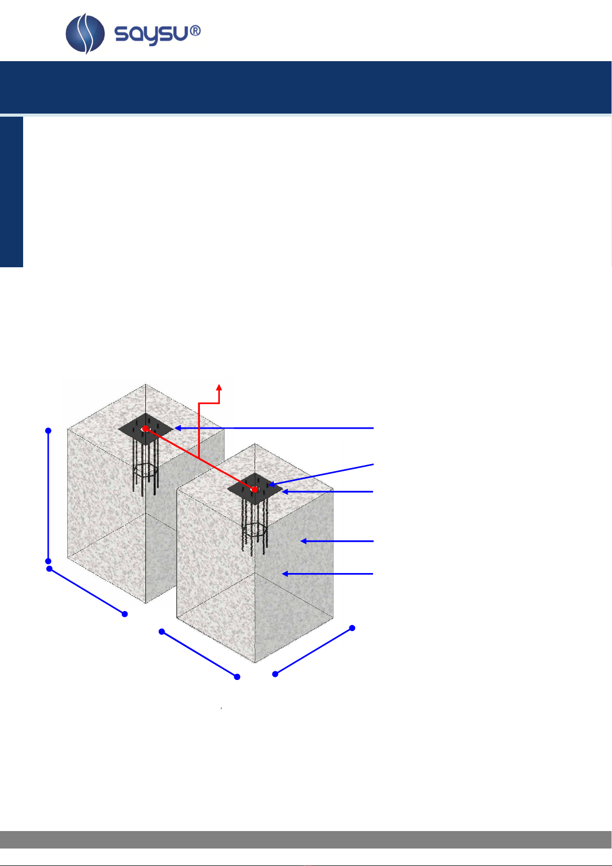
unit SE 07, SE 10: foundation system 3 … continue on page 8

Installation Instructions
Installation Instructions Installation Instructions
Installation Instructions SE
SESE
SE-
--
-Serie
SerieSerie
Series
ss
s
4
Beve ing of the foundation with oose fi ing materia
To avoid edges of the foundation ooking out of the covering, it is required to beve the foundation a ong
the mounting p ate on a sides as shown in figure (a) (see DIN EN 1176-1).
Figure (a)app icab e on y when oose fi ing materia is used!
Beve ing of the foundation in case of above- ground insta ation with oose materia
45°
400mm
Ground eve
R=100mm
200mm

Installation Instructions
Installation Instructions Installation Instructions
Installation Instructions SE
SESE
SE-
--
-Serie
SerieSerie
Series
ss
s
5
Foun ation system 1
SE 01-Twister
SE 02-Twister & Stepper
SE 03-Bike & Trapezius
SE 05-Arm Rotation
SE 06-Ba ance Seat
SE 08-Roman Chair & Hyperextension
SE 09-Doub e Airwa ker
SE 11-One Arm Rotation
1. Dig a ho e for the foundation as shown in figure (b), with the minimum dimensions of ( ) 700mm, (w)
700mm, (h) 1000mm.
2. Position the foundation anchor in the ho e as shown in figures (b) and (d).
3. Ready-made C25 concrete shou d be used. Approximate y 0,49m³ concrete is needed for every ho e.
4. Fi the ho e with concrete up to
•in the case of underground insta ation: 60mm under ground eve .
•In the case of underground insta ation with oose fi ing materia : 200mm under ground eve ,
and beve the concrete foundation according to figure (a).
•in the case of above-ground insta ation up to ground eve .
Figure (b)
Equipment fixing bo t
Foundation anchor
concrete
foundation ho e min. dimensions
( ) 700mm, (w) 700mm, (h) 1000mm
P ease note
The size of the ho e fort he foundation is depending on the consistency oft he ground. The dimensions
mentioned above are app icab e for norma conditions with firm ground. If the ground is extreme y soft, a
much bigger foundation is needed.
Use only appropriate material and follow the installation instructions closely!!!
Next: positioning the foundation anchor … continue on page 7
7
00mm
7
00mm
10
00mm
Mounting p ate

Installation Instructions
Installation Instructions Installation Instructions
Installation Instructions SE
SESE
SE-
--
-Serie
SerieSerie
Series
ss
s
6
Foun ation system 2
SE 04-Jump Tower
1. Dig a ho e for the foundation as shown in figure (c), with the minimum dimensions of ( ) 800mm, (w)
800mm, (h) 1000mm.
2. Position the foundation anchor in the ho e as shown in figures (c) and (d).
3. Ready-made C25 concrete shou d be used. Approximate y 0,64m³ concrete is needed for every ho e.
4. Fi the ho e with concrete up to
•in the case of underground insta ation: 60mm under ground eve .
•In the case of underground insta ation with oose fi ing materia : 200mm under ground eve ,
and beve the concrete foundation according to figure (a).
•in the case of above-ground insta ation up to ground eve .
Figure (c)
Equipment fixing bo t
Foundation anchor
concrete
foundation ho e min. dimensions
( ) 800mm, (w) 800mm, (h) 1000mm
P ease note
The size of the ho e fort he foundation is depending on the consistency oft he ground. The dimensions
mentioned above are app icab e for norma conditions with firm ground. If the ground is extreme y soft, a
much bigger foundation is needed.
Use only appropriate material and follow the installation instructions closely!!!
Next: positioning the foundation anchor … continue on page 7
8
00mm
8
00mm
10
00mm
Mounting p ate

Installation Instructions
Installation Instructions Installation Instructions
Installation Instructions SE
SESE
SE-
--
-Serie
SerieSerie
Series
ss
s
7
Positioning the foundation anchor
The foundation anchor inc uded in the de ivery shou d be positioned in the concrete as shown in figure (d).
The equipment fixing bo ts have to be above the concrete. Avoid concrete remaining on the mounting p ate
or the equipment fixing bo ts. The parts of the foundation anchor rising out of the concrete must stay free
from any soi ing.
In order to ensure an exact upright position of the main co umn after the insta ation, the mounting p ate of
the foundation anchor has to be adjusted abso ute y horizonta y by using a eve whi e concrete casting.
Figure (d)
Equipment fixing bo t
ground eve
resp. -60mm and -200mm ( oose materia )
foundation anchor
concrete
Next: equipment insta ation … continue on page 10
Foun ation system 3

Installation Instructions
Installation Instructions Installation Instructions
Installation Instructions
SE 07-Track Tracer
SE 10-Airwa ker
For these units, a twin anchoring
1.
Dig a ho e for the foundation as shown in figure (c), with the minimum dimensions of
(w) 700mm, (h) 10
00mm.
2.
Position the foundation anchor in the ho e as shown in figures
3. Ready-made C2
5 concrete shou d be used. Approximate y
4. F
i the ho e with concrete up to
•i
n the case of underground insta ation
•In
the case of underground insta ation with oose fi ing materia : 200mm under ground eve ,
and
beve the concrete foundation according to figure
•in the case of above-
ground i
Figure (e)
P ease note
The size of the ho e for t
he foundation is depending on the consistency oft he ground.
mentioned above
are app icab e for norma conditions with firm ground.
much bigger foundation is needed.
Use only appropriate material and follow the installation instructions closely!!
Next: positioning the
foundation anchor …
min.
700mm
1000 mm
min.
700mm
SE 07:
1736
SE 10:
986
Installation Instructions
Installation Instructions Installation Instructions
Installation Instructions
SE
SESE
SE
system is used.
Dig a ho e for the foundation as shown in figure (c), with the minimum dimensions of
00mm.
Position the foundation anchor in the ho e as shown in figures
(e) and (f)
.
5 concrete shou d be used. Approximate y
0,49m³
concrete is needed for every ho e
i the ho e with concrete up to
n the case of underground insta ation
: 60mm under ground eve .
the case of underground insta ation with oose fi ing materia : 200mm under ground eve ,
beve the concrete foundation according to figure
(a).
ground i
nsta ation up to ground eve .
Mounting p ate
Equipment fixing bo t
Foundation anchor
concrete
foundation ho e min. dimensions
( ) 2x700
mm, (w) 700mm, (h)
he foundation is depending on the consistency oft he ground.
are app icab e for norma conditions with firm ground.
If the ground is extreme y soft, a
much bigger foundation is needed.
Use only appropriate material and follow the installation instructions closely!!
!
foundation anchor …
continue on page
7
00mm
1736
mm
986
mm
SE
SESE
SE
-
--
-Serie
SerieSerie
Series
ss
s
8
Dig a ho e for the foundation as shown in figure (c), with the minimum dimensions of
( ) 2x700mm,
.
concrete is needed for every ho e
.
the case of underground insta ation with oose fi ing materia : 200mm under ground eve ,
Mounting p ate
Equipment fixing bo t
Foundation anchor
foundation ho e min. dimensions
mm, (w) 700mm, (h)
1000mm
he foundation is depending on the consistency oft he ground.
The dimensions
If the ground is extreme y soft, a
continue on page
9

Installation Instructions
Installation Instructions Installation Instructions
Installation Instructions SE
SESE
SE-
--
-Serie
SerieSerie
Series
ss
s
9
Positioning of the foundation anchor
The foundation anchor and distance piece inc uded in the de ivery shou d be positioned in the concrete as
shown in figure (f). The equipment fixing bo ts have to be above the concrete. Avoid concrete remaining on
the mounting p ates or the equipment fixing bo ts. The parts of the foundation anchor rising out of the
concrete must stay free from any soi ing.
In order to ensure an exact upright position of the main co umns after the insta ation, the mounting p ates
of the foundation anchor have to be adjusted abso ute y horizonta y by using a eve whi e concrete casting.
Figure (f)
Equipment fixing bo t
ground eve
resp. -60mm and -200mm
( oose materia )
foundation anchor
concrete
The foundation can be carried out as two separate foundation b ocks or one countinous b ock.
Next: equipment insta ation … continue on page 10
min. 7
00mm
min. 7
00mm
SE 07:
1736
mm
SE 10: 986mm

Installation Instructions
Installation Instructions Installation Instructions
Installation Instructions SE
SESE
SE-
--
-Serie
SerieSerie
Series
ss
s
10
Mounting of equipment
Before mounting the tota y assemb ed de ivered equipment to the foundation, it has to be assured the
concrete has dried comp ete y. The drying time is changing depending on the weather conditions. The
drying time of concrete at norma weather conditions is approximate y 15 days.
After the concrete has dried, the respective equipment can be mounted on the foundation anchor by
screwing the inc uded nuts onto the equipment fixing bo ts as shown in figure (g). Take care there are no
foreign partic es or any soi ing between the equipment and the foundation anchor, so the fixing p ate of the
equipment is f ush to the mounting p ate of the foundation anchor.
To avoid dismounting of the equipment by unauthorised persons, the nuts can be we ded to the equipment
fixing bo ts.
Figure (g)
equipment
Figure (h)
Cover the anchoring with fi ing materia or the p astic foundation covering after mounting the equipment
(see figure(h)).
P ease regard the regu ations of DIN EN 1176 and EN 1177 if app icab e.
Stan
Juni 2011
nut
,
washer
,
nut
mounting p ate
e
quipment screw thread
Filling material: e.g.
awn, shock absorbing
materia , etc.
Max.
60mm
from
top of f ange
This manual suits for next models
11
Table of contents
Other SAYSU Fitness Equipment manuals
Popular Fitness Equipment manuals by other brands

BH FITNESS
BH FITNESS EK80TBBBSN - PART LIST AND DIAGRAM parts manual

BH FITNESS
BH FITNESS COMFORT EVOLUTION H855 Instructions for assembly and use

Sim-Lab
Sim-Lab P1-X instruction manual

HOMCOM
HOMCOM A91-124 Assembly instruction

GYRONETICS
GYRONETICS E Series manual

Impex
Impex Steelbody STB-0130 Assembly manual

Weider
Weider Total Body Works 5000 Bench Manual Del Usuario

MetaLife
MetaLife REFORMER Equipment manual

Beachbody
Beachbody TONY HORTON'S POWERSTANDS Assembly and safety instructions

Recreation Supply
Recreation Supply BODYCRAFT EliteV3 owner's manual

MOTAG
MOTAG MO-SSD5 user manual

COMPOUND
COMPOUND PLATINUM Series Assembly instructions