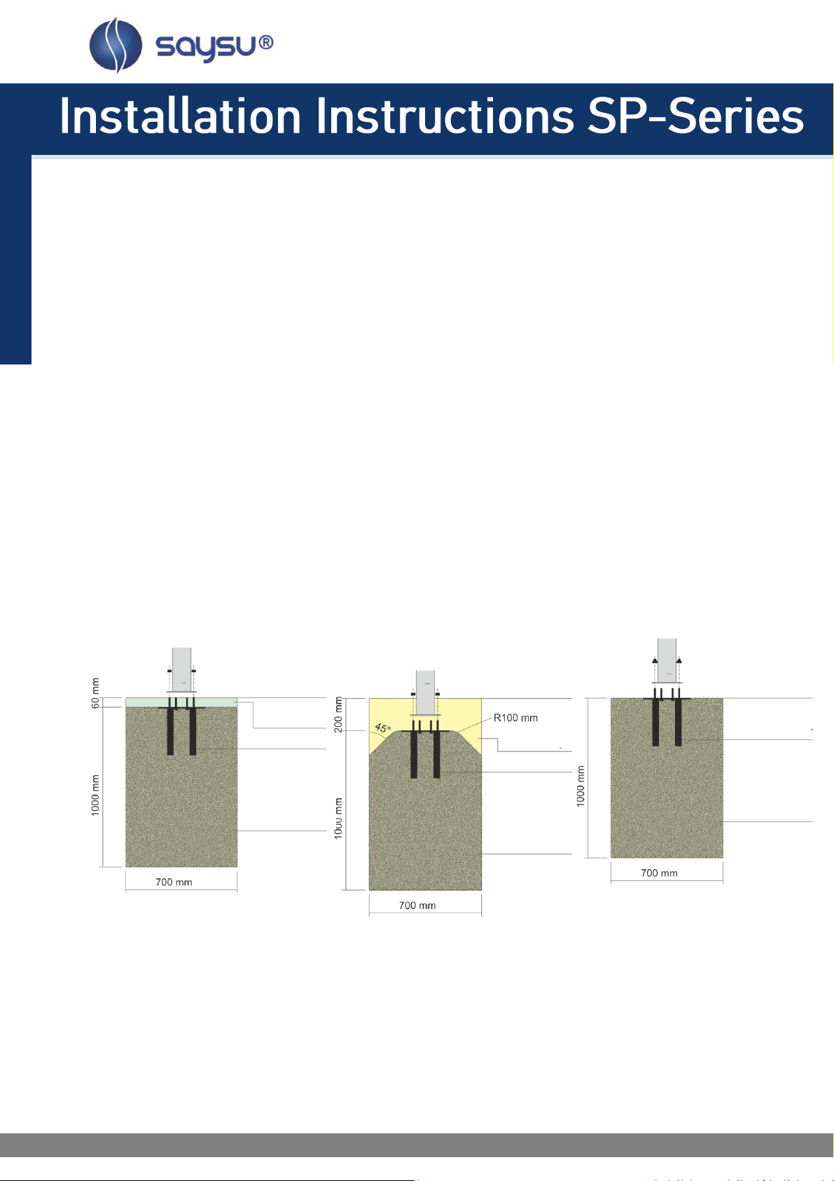
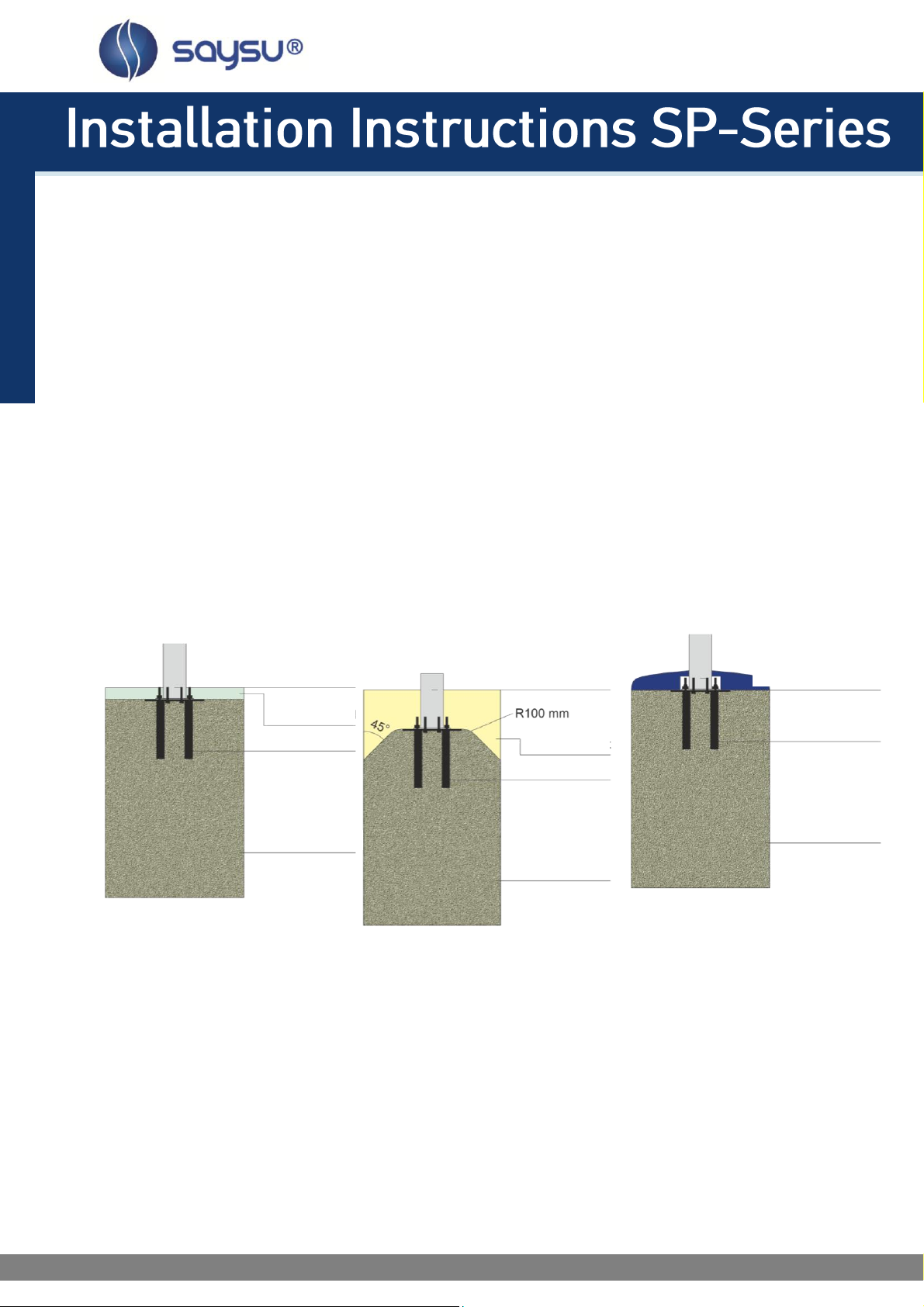
Under-ground installation
For underground installation the foundation is created 60mm below ground level and the anchoring will be
filled up to the ground level (see mark on main column) with the filling material (see figure (a)). Then only
the main column of the equipment rises out of the ground. The top ends of the screws have to be carried
out in compliance with DIN EN 1176-1:2008 (D) 4.2.5.
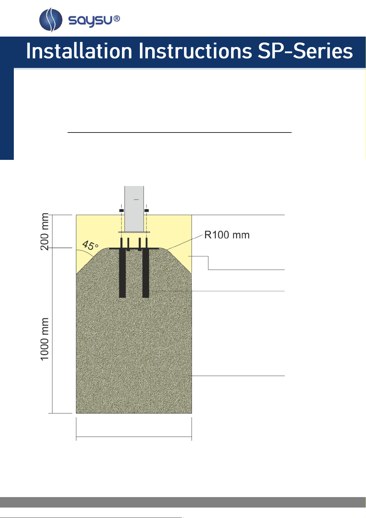
Under-ground installation with loose material
If you use loose material like sand, gravel, mulch or wood chips, then you have to built the foundation
200mm below ground level and bevel the foundation around the mounting plate(see figure (a), (g) and (h)).
After installation, the anchoring will be filled up to ground level with the filling material. Then only the main
column of the equipment rises out of the ground. The top ends of the screws have to be carried out in
compliance with DIN EN 1176-1:2008 (D) 4.2.5.
Above-ground installation
Not possible when using loose material. For above-ground installation the foundation is created at ground
level. In this case the anchoring should be covered with the plastic foundation covering (see figure (a)). The
top ends of the screws have to be carried out in compliance with DIN EN 1176-1:2008 (D) 4.2.5.
Figure (a)
Under-ground installation Under-ground installation Above-ground installation
with loose material
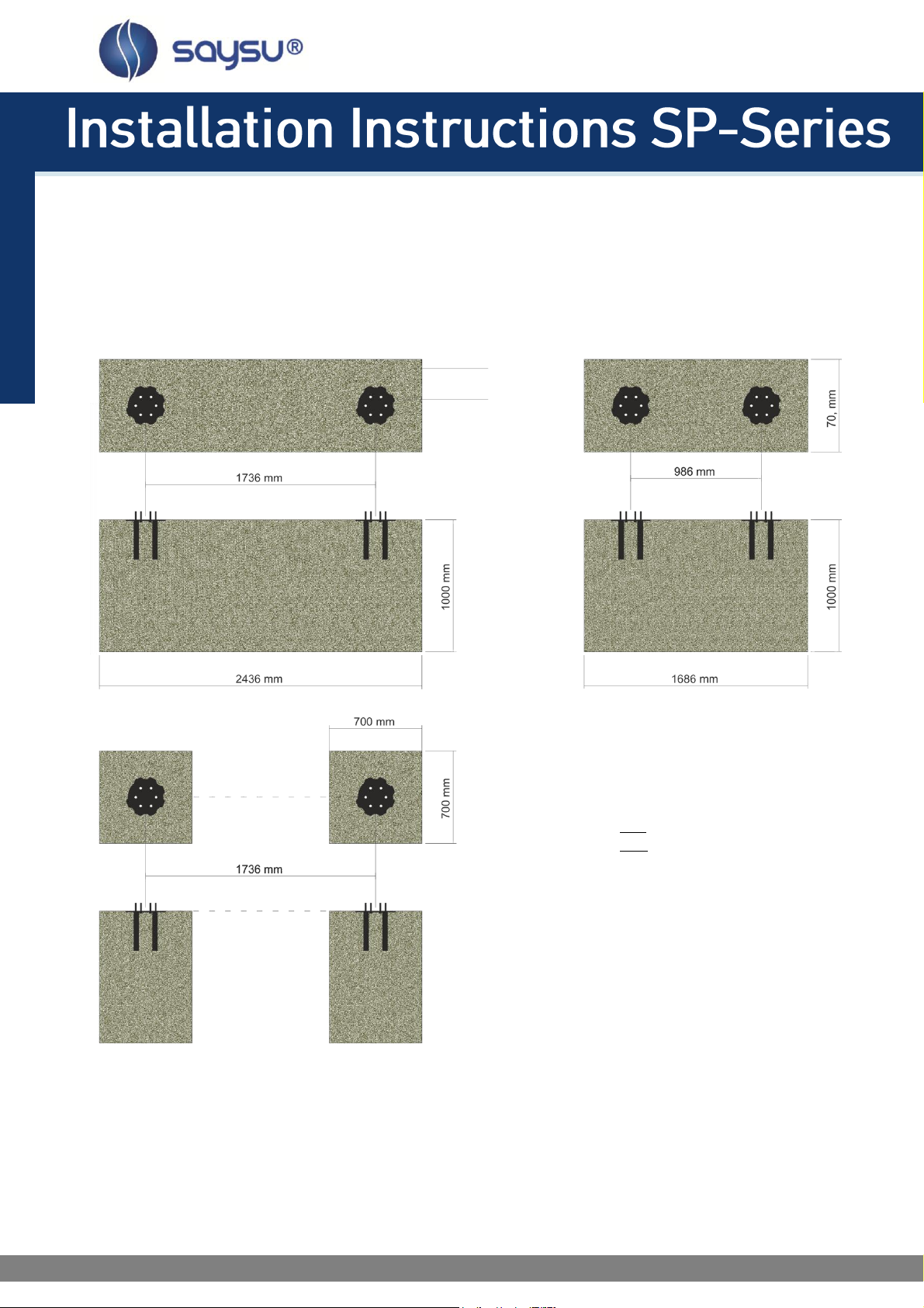
Foundation system 1 or 2
The following overview shows you, which of the foundation system is used for which units:
units SE 01- 03, SE 05-06, SE 08-09, SE 11: foundation system 1 … continue on page 4
unit SE 04: foundation system 2 … continue on page 5
unit SE 07, SE 10: foundation system 3 … continue on page 6