manuals.online logo
Brands
  1. Home
  2. •
  3. Brands
  4. •
  5. SBI
  6. •
  7. Power Tools
  8. •
  9. SBI AC01387 User manual

SBI AC01387 User manual

This manual suits for next models

2

Popular Power Tools manuals by other brands

ISLAND HOPPER Power Egg HT-309 operating instructions

ISLAND HOPPER

ISLAND HOPPER Power Egg HT-309 operating instructions

Sioux Tools SSR6P25 Instructions-parts list

Sioux Tools

Sioux Tools SSR6P25 Instructions-parts list

Makita HM1317C technical information

Makita

Makita HM1317C technical information

ABB Smart Tool + quick start guide

ABB

ABB Smart Tool + quick start guide

Baumr-AG BMJK-24S user manual

Baumr-AG

Baumr-AG BMJK-24S user manual

Bosch Professional GST 18 V-LI S Original instructions

Bosch

Bosch Professional GST 18 V-LI S Original instructions

Ronix RA-2702 quick start guide

Ronix

Ronix RA-2702 quick start guide

Nordson ProBlue user guide

Nordson

Nordson ProBlue user guide

aoyue int6028 instruction manual

aoyue

aoyue int6028 instruction manual

Hitachi CJ 65VA2 Instruction manual and safety instructions

Hitachi

Hitachi CJ 65VA2 Instruction manual and safety instructions

Makita HM1304 instruction manual

Makita

Makita HM1304 instruction manual

Kurtz Ersa Ersa X-TOOL VARIO operating instructions

Kurtz Ersa

Kurtz Ersa Ersa X-TOOL VARIO operating instructions

SCHUNK KSO 65 Installation and operating instruction

SCHUNK

SCHUNK KSO 65 Installation and operating instruction

Harken LokHead 500 user manual

Harken

Harken LokHead 500 user manual

Senco DuraSpin ExTPro installation instructions

Senco

Senco DuraSpin ExTPro installation instructions

Ferm JSM1020 Original instructions

Ferm

Ferm JSM1020 Original instructions

Milwaukee M12 FUEL 2559-20 Operator's manual

Milwaukee

Milwaukee M12 FUEL 2559-20 Operator's manual

EINHELL BT-CD 12/2 operating instructions

EINHELL

EINHELL BT-CD 12/2 operating instructions

manuals.online logo
manuals.online logoBrands
  • About & Mission
  • Contact us
  • Privacy Policy
  • Terms and Conditions

Copyright 2025 Manuals.Online. All Rights Reserved.

45823A
Printed in Canada 11-12-2015
Blower for hot air gravity distribution kit - modern
style with adjustable pipes (AC01389)
AC01387 (240v) or AC01388 (120v)
INSTALLATION INSTRUCTIONS
THE BLOWER IS AN OPTION TO THE HOT AIR GRAVITY DISTRIBUTION KIT -
MODERN STYLE WITH ADJUSTABLE PIPES (AC01389).
Thismanualisavailableforfreedownloadonthemanufacturer’swebsite.Itisacopyrighted
document.Re‐saleisstrictlyprohibited.Themanufacturermayupdatethismanualfromtimeto
timeandcannotberesponsibleforproblems,injuries,ordamagesarisingoutoftheuseof
informationcontainedinanymanualobtainedfromunauthorizedsources.
2
This assembly contains the following parts:
(A) (B)
(C)
(D)
1x 1x 1x 1x
(E)
(F)
(G)
(H)
2x 2x 1x 1x
(I)
(J)
(K)
(L)
1x 5x 1x 1x
(M)
(N)
(O)
4x 1x 1x
3
Tools required for the installation:
Robertson #2 screwdriver Phillips screwdriver Power-driver with 5/16"
(8 mm) hex head
Ratchet with 11/32" (9 mm) hex head
4
BLOWER OPTION INSTALLATION
A thermal switch must be installed for proper blower operation. To do so, follow these
steps.
WARNING: ENSURE THAT THE POWER IS OFF BEFORE STARTING
INSTALLATION.
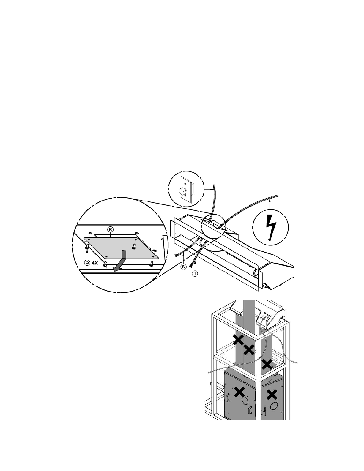
1- Remove the 4 screws (Q) of the junction box’s localization cap (R). Save the screws.
2- From the rheostat, bring the cable (S) (14/2 AWG) from above and through the
opening in the air distribution box.
3- From your electrical panel, bring a cable (T) (14/2 AWG) through the same opening
as the Step 2.
Caution: make sure that the two cables
(S) and (T) comply with all minimum
clearances to combustibles specified in
the manual or on the certification plate of
the fireplace, then attach them to the wall
structure to prevent them from coming into
contact with a hot part of the fireplace or
air distribution system.
5
4- Pass the rheostat cable (S) and that of the power supply (T) through the respective
connectors (E) and plastic sleeves (F) of the junction box (C).
5- Skin the wires/cables (S) and (T).
6- Set blower (A) to the center of the air distribution box and secure it with the self-
piercing screw (N) and the washer (O).
6
7- Route the wires (U) (with connector) and (V) (without connector) from the blower
motor through the wire grommet of the thermal switch bracket (B). Connect the wire
with connector (U) on one of the two poles of the thermal switch.
For next steps, see the wiring diagram
8- With a wire connector (Marrette) (M1), join the white wire of cable (T) to the wire (V)
of the blower motor.
9- Connect the supplied wire (L) to the second pole of the thermal switch.
10-With a wire connector (Marrette) (M2), join the other end of wire (L) to the white wire
of cable (S).
11-With a wire connector (Marrette) (M3), join the black wire of cable (S) to the black
wire of cable (T).
12-Using a wire connector (Marrette) (M4), join the ground wires of cables (S) and (T) to
the wire (K) provided. Then attach the star shaped connector on the junction box (C)
using the screws (I) and the nut (J).
7
Wiring diagram
S
T
8
13-Set the junction box (C) on the thermal switch support (B) using 4 nuts (J). Then,
secure the thermal switch support to the air distribution box with 4 screws (Q) from
Step 1.