SBS Technologies IndustryPack PCI-60A User manual

-~
ARTISAN
®
~I
TECHNOLOGY
GROUP
Your definitive source
for
quality
pre-owned
equipment.
Artisan Technology
Group
Full-service,
independent
repair
center
with
experienced
engineers
and
technicians
on staff.
We
buy
your
excess,
underutilized,
and
idle
equipment
along
with
credit
for
buybacks
and
trade-ins
.
Custom
engineering
so
your
equipment
works
exactly as
you
specify.
•
Critical
and
expedited
services
•
Leasing
/
Rentals/
Demos
• In
stock/
Ready-to-ship
•
!TAR-certified
secure
asset
solutions
Expert
team
ITrust
guarantee
I
100%
satisfaction
All
tr
ademarks,
br
a
nd
names, a
nd
br
a
nd
s a
pp
earing here
in
are
th
e property of
th
e
ir
r
es
pecti
ve
ow
ner
s.
Find the Abaco Systems / SBS / Greenspring PCI-60A-8/32 at our website: Click HERE

© SBS Technologies, Inc.
Subject to change without notice.
Hardware Revision: B
Part #: 89004710 Rev. 5.1
20051110
PCI-60A
Hex IndustryPack®
Carrier for the PCI Bus
User Manual
Artisan Technology Group - Quality Instrumentation ... Guaranteed | (888) 88-SOURCE | www.artisantg.com

PCI-60A
Hex IndustryPack®
Carrier Board For The
PCI Bus
SBS Technologies, Inc.
1284 Corporate Center Drive
St. Paul, MN 55121-1245
Tel: (651) 905-4700
FAX: (651) 905-4701
http:\\www.sbs.com
©2000-2005 SBS Technologies, Inc.
IndustryPack is a registered trademark of SBS
Technologies, Inc. QuickPack, SDpacK and Unilin are
trademarks of SBS Technologies, Inc. PC•MIP is a
trademark of SBS Technologies, Inc. and MEN Micro
Inc.
SBS Technologies, Inc. acknowledges the trademarks
of other organizations for their respective products
mentioned in this document.
A
ll rights are reserved: No one is permitted to
reproduce or duplicate, in any form, the whole or part
of this document without the express consent of SBS
Technologies. This document is meant solely for the
purpose for which it was delivered.
SBS Technologies reserves the right to make any
changes in the devices or device specifications
contained herein at any time and without notice.
Customers are advised to verify all information
contained in this document.
The electronic equipment described herein generates,
uses, and may radiate radio frequency energy, which
can cause radio interference. SBS Technologies
assumes no liability for any damages caused by such
interference.
SBS Technologies’ products are not authorized for
use as critical components in medical applications,
such as life support equipment, without the express
consent of the president of SBS Technologies.
This product has been designed to operate with
IndustryPack, PC•MIP or PMC modules or carriers,
and compatible user-provided equipment. Connection
of incompatible hardware is likely to cause serious
damage. SBS Technologies assumes no liability for
any damages caused by such incompatibility.
Artisan Technology Group - Quality Instrumentation ... Guaranteed | (888) 88-SOURCE | www.artisantg.com

Table of Contents
PRODUCT DESCRIPTION_________________________________________________1
KEY FEATURES _________________________________________________________1
ADDRESS MAP _________________________________________________________2
I/O CONNECTIONS_______________________________________________________2
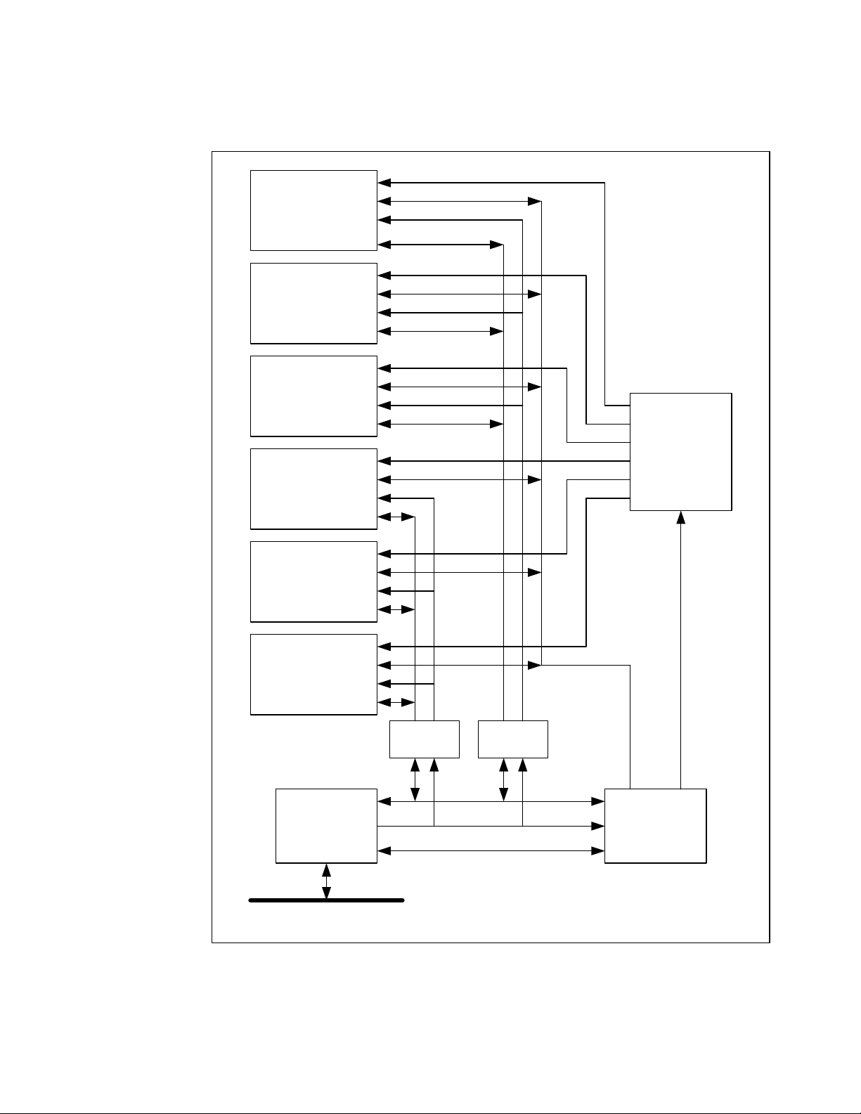
BLOCK DIAGRAM ________________________________________________________3
PCI-60A HARDWARE OVERVIEW __________________________________________4
ADDRESSING OVERVIEW __________________________________________________4
SELECTING THE PCI-60A BASE ADDRESS______________________________________4
I/O SPACE ____________________________________________________________6
ID SPACE _____________________________________________________________7
MEMORY SPACE ACCESSES________________________________________________7
INTERRUPT SPACE_______________________________________________________8
INDUSTRYPACK BUS TIME-OUT _____________________________________________8
STATUS AND CONTROL REGISTER BIT MAPS____________________________________9
INDUSTRYPACK BUS PIN ASSIGNMENTS ______________________________________12
INDUSTRYPACK I/O PIN ASSIGNMENTS _______________________________________13
POWER______________________________________________________________13
PROGRAMMING _______________________________________________________14
PROGRAMMING THE PCI 9080 REGISTERS ____________________________________15
PCI 2.1 Mode______________________________________________________ 15
Read Ahead Mode__________________________________________________ 16
INTERRUPTS __________________________________________________________16
WRITE POSTING _______________________________________________________17
OTHER FEATURES_____________________________________________________18
LED INDICATORS_______________________________________________________18
FUSES ______________________________________________________________19
INSTALLATION OF INDUSTRYPACKS _____________________________________20
USER I/O WIRING ______________________________________________________21
USER OPTIONS________________________________________________________22
SWITCH SW1 _________________________________________________________22
E1 -INDUSTRYPACK STROBE______________________________________________23
CONSTRUCTION AND RELIABILITY_______________________________________24
SPECIFICATIONS ______________________________________________________25
APPENDIX A - DOS EXTENDERS _________________________________________26
REPAIR ______________________________________________________________27
SERVICE POLICY _______________________________________________________27
Artisan Technology Group - Quality Instrumentation ... Guaranteed | (888) 88-SOURCE | www.artisantg.com

List of Figures
FIGURE 1. BLOCK DIAGRAM ________________________________________________3
FIGURE 2. STANDARD MEMORY MAP -64 MB ___________________________________5
FIGURE 3. REDUCED MEMORY MAP -64 KB ____________________________________6
FIGURE 4. REQUIRED INDUSTRYPACK ID PROM INFORMATION_______________________7
FIGURE 5. INDUSTRYPACK BUS PIN ASSIGNMENTS_______________________________12
FIGURE 6. PCI CONFIGURATION REGISTERS ___________________________________15
FIGURE 7. LED CHART___________________________________________________18
FIGURE 8. FUSE CHART __________________________________________________19
FIGURE 9. INDUSTRYPACK CONNECTOR PIN NUMBERING __________________________21
FIGURE 10. FLAT CABLE CONNECTOR PIN NUMBERING ___________________________21
Artisan Technology Group - Quality Instrumentation ... Guaranteed | (888) 88-SOURCE | www.artisantg.com

1
Product Description
The PCI-60A IndustryPack®carrier board provides six IndustryPack slots on a single
desktop or industrial PCI slot card. The PCI-60A-8 provides an 8 MHz clock to all
IndustryPack slots. The PCI-60A-8/32 provides a clock that is software-selectable on a
per-slot basis and has an overall higher performance level.
The standard 8 MB memory space is available for each IndustryPack site. High-speed
32-bit PCI host address space permits desirable linear mapping and fixed address
partitions of memory, I/O, and ID spaces for each IndustryPack module.
The PCI-60A uses a PLX PCI9080 controller as the PCI bus interface chip and Altera
FPGA logic, which provides fully configurable PCI interrupt vector space. The PCI bus
interface handles 3.3V and 5.0 V signaling levels.
Each IndustryPack site has an adjacent 50-pin I/O connector for exiting the host system
through the PCI slot panel. One connector is accessible via the rear-panel. The standard
connector allows most of SBS transition modules and terminal blocks to be used.
The PCI-60A meets the PCI specification and conforms to the VITA-4 IndustryPack Logic
Interface Specification. This guarantees compatibility with a wide range of IndustryPacks.
The PCI-60A is backward compatible with the PCI-40A.
Key Features
•Six IndustryPack slots on a single PCI slot board
•I/O via six 50-pin keyed, shrouded ribbon cable headers
•Switchable 8/32 MHz IndustryPack bus
•LEDs for CPU access and power monitor for each slot
•Filtered power rails and resettable fuses
•Interrupt acknowledge space for retrieving IndustryPack vectors
•Backwards-compatible with the PCI-40A
•Reduced memory-map version available by special order
Artisan Technology Group - Quality Instrumentation ... Guaranteed | (888) 88-SOURCE | www.artisantg.com

2
Address Map
The PCI-60A is mapped into the PCI memory space. PCI I/O space is not used.
IndustryPack I/O, ID, memory, and interrupt vector registers are mapped in the PCI
memory space. Two address maps are supported: a standard memory map consuming
64 Mbytes of address space and a small memory map consuming 64 Kbytes. Size is an
order option.
The PCI bus allocates only one interrupt line to the PCI-60A per the PCI 2.1
Specification. The PCI-60A, however, provides an interrupt status register that quickly
identifies that IndustryPack slot generated the interrupt.
I/O Connections
The six IndustryPack positions are referred to as slots and identified by the letters A, B,
C, D, E, and F. Five of the slots have upright 50-pin flat cable headers accessible through
the rear panel of the PCI-60A for their I/O connections. The sixth slot has a right angle
connector available directly from the rear panel. The I/O connectors are mounted directly
on the PCI-60A board to provide a modular and reliable cabling system with inherent
strain relief. I/O cables may be inserted or removed without removing the PCI-60A from
the chassis. IndustryPacks in slots A and B may be installed or removed without
interfering with the I/O cabling.
PCI-60A provides protected and filtered +5V, +12V, and -12V supplies to each
IndustryPack by means of passive "T" filters, capacitors, and fuses. The three terminal
filters provide excellent RF rejection of power supply conducted noise. This permits use
of precision analog IndustryPacks together with high-speed digital IndustryPacks in the
same PCI-60A. The fuses are self-resetting Positive Temperature Coefficient devices.
The IndustryPack slots feature other power handling features such as separated ground
planes to reduce conducted noise.
PCI-60A IndustryPack interface is compliant with the ANSI/VITA 4 IndustryPack Module
Specification Revision 1.0. This guarantees compatibility with the wide range of
IndustryPacks currently available and planned.
Figure 1 is a block diagram of the PCI-60A.
Artisan Technology Group - Quality Instrumentation ... Guaranteed | (888) 88-SOURCE | www.artisantg.com

3
Block Diagram
Figure 1. Block Diagram
Industry Pack
Slot F
Industry Pack
Slot E
Industry Pack
Slot D
Industry Pack
Slot C
Industry Pack
Slot B
Industry Pack
Slot A
PLX PCI
9080
Buffers
Altera
Control
Logic
Clock
Distribution
Buffers
Data
Address
PCI Bus
Control
Data
Address
Address
Data
Artisan Technology Group - Quality Instrumentation ... Guaranteed | (888) 88-SOURCE | www.artisantg.com

4
PCI-60A Hardware Overview
Addressing Overview
IndustryPacks have four separate address spaces across the IndustryPack Logic
interface: ID, I/O, memory, and (interrupt) vector. It is the job of the carrier board, the
PCI-60A, to map these spaces into the host’s address space. The PCI-60A maps all
IndustryPack spaces into the PCI bus memory space.
The IndustryPack I/O, ID, and vector spaces are fixed in size. The IndustryPack memory
size can vary up to 8 MB per IndustryPack. The PCI-60A supports two address maps: a
standard map consuming 64 MB of memory space and a reduced map consuming 64 KB
of memory space. Both memory maps provide the I/O, ID, and INT spaces for the six
slots plus local register decoding. The reduced map provides an additional 2K of memory
space per IndustryPack and the standard map provides an additional 8 MB per
IndustryPack.
Selecting the PCI-60A Base Address
The PCI-60A base address and address map are selected through the PCI configuration
registers. Unlike VME and ISA systems, the base addresses in PCI systems are set at
run time by the BIOS. The BIOS uses PCI configuration cycles to query each slot on the
PCI bus. Upon detecting a card, the BIOS writes all Fs to the Base Address Registers
(BARs) and then reads them back. The card responds by placing 0s in all the address
bits that it uses. The BIOS uses this information to determine how much memory the card
is requesting, then assigns an address and writes it back to the BAR.
There are three base address registers for the PCI-60A. The first, BAR0, is the address
of the PCI-9080 PCI accessible registers in PCI memory space. The second, BAR1, is
the address of the PCI-9080 PCI accessible registers in PCI IO space. The third address,
BAR2, is the address to use for accessing the IndustryPacks and PCI-60A Local Control
registers in PCI memory space. The PCI-60A does not use the PCI-9080 BAR for local
spaces. The addresses depicted in Figures 2 and 3 are relative to contents of BAR2.
Please refer to the Programming section for more information.
Note that addresses within each IndustryPack's space are specific to that IndustryPack.
Refer to each IndustryPack’s User Manual for specific addressing information.
Artisan Technology Group - Quality Instrumentation ... Guaranteed | (888) 88-SOURCE | www.artisantg.com

5
Address Name
From To
0000 0500 0000 07FF PCI-60A Local Control
0000 1000 0000 10FF SlotA I/O
0000 1100 0000 11FF SlotA ID
0000 1200 0000 12FF SlotA INT
0000 2000 0000 20FF SlotB I/O
0000 2100 0000 21FF SlotB ID
0000 2200 0000 22FF SlotB INT
0000 3000 0000 30FF SlotC I/O
0000 3100 0000 31FF SlotC ID
0000 3200 0000 32FF SlotC INT
0000 4000 0000 40FF SlotD I/O
0000 4100 0000 41FF SlotD ID
0000 4200 0000 42FF SlotD INT
0000 5000 0000 50FF SlotE I/O
0000 5100 0000 51FF SlotE ID
0000 5200 0000 52FF SlotE INT
0000 6000 0000 60FF SlotF I/O
0000 6100 0000 61FF SlotF ID
0000 6200 0000 62FF SlotF INT
0100 0000 017F FFFF SlotA MEM
0180 0000 01FF FFFF SlotB MEM
0200 0000 027F FFFF SlotC MEM
0280 0000 02FF FFFF SlotD MEM
0300 0000 037F FFFF SlotE MEM
0380 0000 03FF FFFF SlotF MEM
Figure 2. Standard Memory Map - 64 MB
Artisan Technology Group - Quality Instrumentation ... Guaranteed | (888) 88-SOURCE | www.artisantg.com

6
Address Name
From To
0000 0500 0000 07FF PCI-60A Local Control
0000 5000 0000 57FF SlotA MEM
0000 5800 0000 5FFF SlotB MEM
0000 6000 0000 67FF SlotC MEM
0000 6800 0000 6FFF SlotD MEM
0000 7000 0000 77FF SlotE MEM
0000 7800 0000 7FFF SlotF MEM
0000 9000 0000 90FF SlotA I/O
0000 9100 0000 91FF SlotA ID
0000 9200 0000 92FF SlotA INT
0000 A000 0000 A0FF SlotB I/O
0000 A100 0000 A1FF SlotB ID
0000 A200 0000 A2FF SlotB INT
0000 B000 0000 B0FF SlotC I/O
0000 B100 0000 B1FF SlotC ID
0000 B200 0000 B2FF SlotC INT
0000 C000 0000 C0FF SlotD I/O
0000 C100 0000 C1FF SlotD ID
0000 C200 0000 C2FF SlotD INT
0000 D000 0000 D0FF SlotE I/O
0000 D100 0000 D1FF SlotE ID
0000 D200 0000 D2FF SlotE INT
0000 E000 0000 E0FF SlotF I/O
0000 E100 0000 E1FF SlotF ID
0000 E200 0000 E2FF SlotF INT
Figure 3. Reduced Memory Map - 64 KB
I/O Space
The I/O space on each IndustryPack is fixed at 128, 16-bit words (256 Bytes). (The I/O
space above 64 words is for future use.) This occupies a space of $100 Bytes. The six
IndustryPack I/O spaces are accessible at fixed offsets from the PCI-60A's Base
Address, as shown in Figures 2 and 3. Typically, IndustryPacks do not fully decode their
entire 64 long-word space. Some IndustryPacks support both word and byte accesses to
I/O space, while others require accesses to be byte-only or word-only. See each
IndustryPack's User Manual for details.
Caution: An IndustryPack may or may not fully decode its I/O space. Incomplete
decoding will often cause IndustryPack registers to appear in multiple places within the
64-word I/O space. IndustryPacks may have different read and write maps. Some
IndustryPacks require 16-bit accesses only. If an IndustryPack does not respond to an
invalid access, then the PCI-60A bus timer will respond [if enabled] and cause an
interrupt to alert the software.
Artisan Technology Group - Quality Instrumentation ... Guaranteed | (888) 88-SOURCE | www.artisantg.com

7
ID Space
Every IndustryPack must have an ID PROM. The ID space on each IndustryPack is fixed
at 128, 16-bit words. The ID space above 32 Bytes is for future use. The ID PROM is
required by the ANSI/VITA 4 IndustryPack Module Specification 1.0. The ID PROM data
is at least 12 Bytes and is found in the lowest byte of the first 12 words. Newer
IndustryPacks may support the ID PROM Data Format II that uses 16-bit words instead
of 8-bit bytes. The ID PROM provides information about the IndustryPack, which is
defined in the IndustryPack Specification and the IndustryPack's User Manual. This
information includes the IndustryPack's manufacturer, model code, and manufacturing
revision level. It may also include a driver identification code and calibration information.
The figure below lists the required information in each ID PROM. For additional
information, see the IndustryPack Specification and the Users Manual for each
IndustryPack.
$FF
user space
2A
2*nn
pack specific space
$18
$16 CRC
$14 No of bytes used [ = nn ]
$12 Driver ID, high byte
$10 Driver ID, low byte
$0E reserved ($00)
$0C Revision
$0A Model No
$08 Manufacturer ID
$06 ASCII "C" ($43)
$04 ASCII "A" ($41)
$02 ASCII "P" ($50)
$00 ASCII "I" ($49)
Figure 4. Required IndustryPack ID PROM Information
Memory Space Accesses
The use of IndustryPack memory space is optional, and two sizes are available.
Implementation among IndustryPacks varies widely. It may be used for RAM, EPROM,
Flash, video frame buffers, communication data buffers, SRAM, local processor space,
expanded register space, special functions, or a combination thereof. The memory is
generally, but not always, 16-bits wide.
The PCI-60A supports two configurations of IndustryPack memory space. The standard
map allocates the full 8 MB of space per IndustryPack. The reduced map configuration
allocates a 2 KB partition for each of the six IndustryPacks. This is adequate to service
many IndustryPacks that use the memory space as an alternate or expanded register
space. It is not sufficient for some IndustryPack designs that implement real memory in
Artisan Technology Group - Quality Instrumentation ... Guaranteed | (888) 88-SOURCE | www.artisantg.com

8
this space. Because this space is within the address decoding of the IndustryPack
Memory space, the 2K block will appear at memory address 0 only for slot A. The other
slots will be offset from 0 in 2K increments.
Interrupt Space
The PCI-60A maps all interrupt levels to the INTA# signal on the PCI back plane as
required for single function devices by the PCI Specification 2.1. Because the PCI
interrupts are shared, an interrupt can be from any slot on the back plane or from the
motherboard itself. The interrupt service routine (ISR) must first check that the interrupt
came from the PCI-60A by reading the CNTL2 register on the PCI-60A. If an
IndustryPack is requesting the interrupt, the CNTL1 register can be read to determine
which one. Each of the twelve IndustryPack interrupt lines (2 per IndustryPack) has a bit
in this register. An interrupt will be generated whenever one of these bits is set and
interrupts are enabled. It is up to the ISR to prioritize multiple interrupts if more than one
bit is set. Each bit can be cleared only by clearing the interrupt source on the Industry
Pack.
The interrupt space of each IndustryPack slot is directly accessible at any time. Typically,
the ISR will access the INT space to determine the local cause of the interrupt. A read to
the INT space will generate an IndustryPack Interrupt Cycle. During this cycle, the
IndustryPack places its interrupt vector on the data lines. Some IndustryPacks may
require this access to clear the interrupt. Check the IndustryPack's User Manual for
specific details on clearing interrupts.
Please refer to the Control and Status register bit map section for more information.
IndustryPack Bus Time-Out
The PCI-60A has a programmable IndustryPack bus error timer. When enabled, the PCI-
60A will time out if the IndustryPack being accessed does not respond. This allows the
IndustryPack slots to be interrogated during start up to determine what IndustryPacks are
installed in what slots. Without this feature, accessing an IndustryPack slot that does not
respond will usually put the PCI bus in an infinite retry loop, essentially locking up the
host processor.
When the Bus Error feature is enabled, the hardware will create a “bus reply” for an
IndustryPack that does not respond within 3.2 µs. The hardware can also generate an
interrupt to the host when the reply is from the timer instead of the IndustryPack.
Interrupts may also be disabled and the bus error timer status may be polled. Three bits
are used to control the way the bus error timer works. The AUTO_ACK bit in CNTL0
enables the bus error timer. When it is set to “1”, the bus error timer will generate an Ack*
whenever an IndustryPack is accessed but does not respond. A status bit in CNTL2,
AUTO_INT_SET, will be set if the CLR_AUTO bit in CNTL0 is set to “1”. Once set, the
AUTO_ INT_SET bit will stay set until the CLR_AUTO bit is cleared to “0”. The AUTO_
INT_SET bit will generate an interrupt if the INT_EN bit in CNTL0 is set to “1” and the
Local Interrupt Enable bit in the PCI 9080 Interrupt Control/Status Register is set to “1”.
With the INT_EN bit cleared to “0”, the AUTO_ INT_SET bit may be polled.
The PCI 9080 always posts to its internal write FIFO before actually performing the write
to the local bus side (i.e., the IndustryPack or CNTRL register). This leads to problems
when a write causes a bus error on the local bus side and the AUTO_ACK feature is not
enabled. The write appears to complete with no problems. However, the next access to
the PCI-60A puts the PCI bus in an infinite retry loop as the PCI 9080 is still waiting for
the previous access to complete. This effectively locks up the host computer.
Please refer to the Bit Map section for more information.
Artisan Technology Group - Quality Instrumentation ... Guaranteed | (888) 88-SOURCE | www.artisantg.com

9
Status and Control Register Bit Maps
Three registers reside within the PCI-60A Local Control space as shown in Figures 2 and
3. The relative offsets and bit map definitions follow:
CNTL0: BAR2 offset 0x00000500 = Control Register 0 [CNTL0]
D15 D14 D13 D12 D11 D10 D9 D8
Unused Unused Unused Unused Unused Unused CLKF CLKE
D7 D6 D5 D4 D3 D2 D1 D0
INTSET INTEN AUTO_ACK CLR_AUTO CLKD CLKC CLKB CLKA
Bit Definition
CLKA 0 = 8 MHz, 1 = 32 MHz for IP slot A
CLKB 0 = 8 MHz, 1 = 32 MHz for IP slot B
CLKC 0 = 8 MHz, 1 = 32 MHz for IP slot C
CLKD 0 = 8 MHz, 1 = 32 MHz for IP slot D
CLR_AUTO 0 = clear, 1 = enable AUTO_INT_SET bit in CNTL2
AUTO_ACK 0 = disable, 1 = enable bus error timer
INTEN 0 = disable interrupts, 1 = enable interrupts
INTSET 0 = turn off, 1 = force local interrupt [INTEN = 1]
CLKE 0 = 8 MHz, 1 = 32 MHz for IP slot E
CLKF 0 = 8 MHz, 1 = 32 MHz for IP slot F
Default value = 0x00. Word access and read-writeable.
CLK[A..F]
The CLKx bits control the clock rate for each IndustryPack. The clock to the slot is always
at the frequency selected. The State Machine clock is altered to match the slot clock rate
for each access automatically. A PLL is used to allow clean switching between
frequencies without “glitching”. For the 8 MHz only version, these bits have no affect.
CLR_AUTO
The CLR_AUTO control bit is used to enable and clear the AUTO_INT_SET bit in
CNTL2. The AUTO_INT_SET bit is held clear when this bit is “0”. Setting this bit to “1”
removes the clear from the AUTO_INT_SET bit, allowing it to be set when the bus error
timer expires and an Ack* is generated for an IndustryPack. Once the AUTO_INT_SET
bit is set, a “0” must be written to the CLR_AUTO bit to clear the AUTO_INT_SET bit.
The CLR_AUTO bit must be set back to “1” to re-enable the AUTO_INT_SET bit. The
CLR_AUTO bit defaults to “0” on power-up or after a reset.
AUTO_ACK
The AUTO_ACK bit enables the auto acknowledge feature when set to “1”. When
enabled, the PCI-60A creates a response to the PCI bus if an IndustryPack does not
respond within 3.2 µsec or is not present. A response will be generated for valid
IndustryPack addresses only. Clearing this bit to “0” will disable this function. If the
CLR_AUTO, AUTO_ACK, and INTEN are all set to “1”, an interrupt will be generated if
the software accesses a location that does not respond. The software must read CNTL2
and, if necessary, CNTL1 to determine the source of the interrupt. AUTO_ACK can be
used with INTEN disabled and CLR_AUTO enabled by polling the status after each
access. The power-up and reset default is “0”.
Artisan Technology Group - Quality Instrumentation ... Guaranteed | (888) 88-SOURCE | www.artisantg.com

10
INTEN
INTEN enables interrupts from the PCI-60A onto the PCI bus when set to “1”. If cleared
to "0", the interrupt remains pending but blocked from the PCI-9080. The PCI-9080 will
cause INTA# of the PCI bus to be asserted if INTEN is enabled and an interrupt source is
active. The PCI-9080 must also be set up to pass interrupts by having its Local Interrupt
Enable bit and the PCI Interrupt Enable bit in the Interrupt Control/Status Register set to
“1”s. Only the PCI Interrupt Enable bit defaults to “1” as set by the EEPROM. The power-
up and reset default is “0”.
INTSET
The INTSET bit is used with INTEN to create an interrupt. The interrupt source is within
the Altera control PLD. With INTEN enabled, setting INTSET to a “1” will generate an
interrupt input to the PCI-9050. If interrupts from the local bus are enabled, the PCI bus
INTA# will be activated. This is a useful feature for debugging.
CNTL1: BAR2 offset 0x00000600 = control register 1 [CNTL1]
Read
D15 D14 D13 D12 D11 D10 D9 D8
Unused Unused Unused Unused IRQF1 IRQF0 IRQE1 IRQE0
D7 D6 D5 D4 D3 D2 D1 D0
IRQD1 IRQD0 IRQC1 IRQC0 IRQB1 IRQB0 IRQA1 IRQA0
Bit Definition [read only]
IRQA0 0 = no interrupt, 1 = interrupt pending
IRQA1 0 = no interrupt, 1 = interrupt pending
IRQB0 0 = no interrupt, 1 = interrupt pending
IRQB1 0 = no interrupt, 1 = interrupt pending
IRQC0 0 = no interrupt, 1 = interrupt pending
IRQC1 0 = no interrupt, 1 = interrupt pending
IRQD0 0 = no interrupt, 1 = interrupt pending
IRQD1 0 = no interrupt, 1 = interrupt pending
IRQE0 0 = no interrupt, 1 = interrupt pending
IRQE1 0 = no interrupt, 1 = interrupt pending
IRQF0 0 = no interrupt, 1 = interrupt pending
IRQF1 0 = no interrupt, 1 = interrupt pending
CNTL1 is read to determine the source of an interrupt request that originates from the
IndustryPack Slots. If an interrupt request is processed by the host CPU originating from
the PCI-60A, then the CPU should read it and CNTL2 to determine which interrupts are
pending. If the IndustryPack requires access in the interrupt space, then a read/write
operation can be performed via the Interrupt space (see memory map) to create an INT
space access to the IndustryPack slot in question. A1 is set by the address within the
space. Access an even word [a1 =0] for INT0 and an odd word for INT1.
Artisan Technology Group - Quality Instrumentation ... Guaranteed | (888) 88-SOURCE | www.artisantg.com

11
CNTL2: BAR2 [read only] offset 0x00000700 = control register 2 [CNTL2]
D15 D14 D13 D12 D11 D10 D9 D8
Unused Unused Unused Unused Unused Unused Unused Unused
D7 D6 D5 D4 D3 D2 D1 D0
LINT Auto_Int_Set unused Unused Unused Unused Unused Unused
Bit Definition [read only]
Auto_Int_Set 0 = no bus error time out, 1 = bus error interrupt pending
LINT 0 = no interrupt, 1 = interrupt pending to PLX
Auto_Int_Set
Auto_Int_Set indicates that a bus error has occurred and that Readyi# was asserted to
prevent the system from hanging up. Please refer to CNTL0 for the Auto_Int_Set control
bits.
LINT
LINT is an active high version of LINT# input to the PCI 9080 and indicates that PCI-60A
is requesting an interrupt when read as "1".
Artisan Technology Group - Quality Instrumentation ... Guaranteed | (888) 88-SOURCE | www.artisantg.com

12
IndustryPack Bus Pin Assignments
The six IndustryPack slots have the standard logic connector pinout as defined by VITA
4-1995 and shown below:
Pin Signal Pin Signal
1 GND 26 GND
2 CLK 27 +5 V
3 Reset* 28 R/W*
4 D0 29 IDSel*
5 D1 30 DMAReq0*
6 D2 31 MemSel*
7 D3 32 DMAReq1*
8 D4 33 IntSel*
9 D5 34 DMAck*
10 D6 35 IOSel*
11 D7 36 [Reserved]
12 D8 37 A1
13 D9 38 DMAEnd*
14 D10 39 A2
15 D11 40 [Error*]
16 D12 41 A3
17 D13 42 IntReq0*
18 D14 43 A4
19 D15 44 IntReq1*
20 BS0* 45 A5
21 BS1* 46 Strobe*
22 -12 V 47 A6
23 +12 V 48 Ack*
24 +5 V 49 [Reserved]
25 GND 50 GND
Figure 5. IndustryPack Bus Pin Assignments
Signals shown within square brackets, such as [Reserved], are not connected on the
PCI-60A. Signals shown within curly braces, such as {Strobe*}, are connected but not
used. All signals except IDSel*, IntSel*, IOSel, MemSel*, IntReq0*, IntReq1*, and Ack*
are bused.
Artisan Technology Group - Quality Instrumentation ... Guaranteed | (888) 88-SOURCE | www.artisantg.com

13
IndustryPack I/O Pin Assignments
The six IndustryPack positions are referred to as slots and identified by the letters A, B,
C, D, E, and F. Each slot's I/O connections are routed to a separate 50-pin IDC
connector which allows the separate ribbon cables to be brought out through the rear
panel. Refer to the I/O Wiring section for more information.
Power
The PCI-60A provides protected and filtered +5V, +12V, and -12V supplies to each
IndustryPack by means of passive "T" filters, capacitors, and fuses. The three terminal
filters provide excellent RF rejection of power supply conducted noise. This permits use
of precision analog IndustryPacks together with high-speed digital IndustryPacks in the
same PCI-60A. The IndustryPack slots feature other power handling features such as
separated ground planes to reduce conducted noise. For more information, refer to the
Fuse Chart depicted Figure 7 in the Other Features section of this manual.
Artisan Technology Group - Quality Instrumentation ... Guaranteed | (888) 88-SOURCE | www.artisantg.com

14
Programming
This section outlines key aspects in programming IndustryPacks installed on the PCI-
60A.
The PCI-60A is normally programmed to occupy space above one megabyte. DOS,
including Microsoft's MS-DOS and IBM's PC-DOS, cannot access space above one
megabyte. "32-bit" operating systems, such as Windows NT, OS-9000, and SCO Unix,
can generally access space above one megabyte. Some operating systems may require
an intermediate piece of software to gain access to the hardware.
The PCI-60A has a Vendor ID of 0x124B and a Device ID of 0x0040. It has a Subsytem
Vendor ID of 0x124B and a Subsystem Device ID of 0. Before use, the PCI-60A must
have its Base Address set by the system. This is done via the PCI configuration registers.
All accesses to the IndustryPacks on the PCI-60A are then relative to the Base Address.
In general, computing an exact address of a register within an IndustryPack requires the
addition of three numbers: the PCI-60A Base Address, the Offset of the IndustryPack's
appropriate I/O space, and the Register Offset within the IndustryPack. Generally, C
structures and C header files are used to perform these additions implicitly. The Offset of
the IndustryPack's I/O space is shown in Figure 2 in the Addressing section of this
manual. The Register Offset is specific to each IndustryPack and is listed in its User
Manual.
The base address is determined during start-up by the PCI BIOS. Each device on the
PCI bus is interrogated during start-up. The BIOS writes out all ones to the BAR, then
reads it back. The card responds with zeroes in all the address bits it decodes. From this,
the BIOS determines how much space the device is requesting and assigns it a base
address. It then writes this address back to the BAR.
The PCI 9080 used on the PCI-60A for a PCI interface has registers that are tested by
the PCI BIOS during initialization. Based upon the results, two memory spaces and one
I/O space are allocated to the PCI-60A. The first memory space is contained in BAR0
and is the address of the PCI-9080 PCI accessible registers referred to as the Local
Configuration Registers, Runtime Registers, and Messaging Queue Registers in the PCI
9080 Datasheet. The second memory space is contained in BAR2 and is the address to
use for accessing the IndustryPacks and PCI-60 as Local Control registers. This is
referred to as the Local Address Space 0 in the PCI-9080 Datasheet. The I/O space for
the PCI 9080 accessible registers is contained in BAR1. Programming of the PCI 9080
registers from the IO space is not recommended. The PCI-60A does not use the PCI-
9080 BAR3 for Local Address Space 0.
The following figure shows a map of the PCI Configuration Registers. Refer to the PCI
2.1 specification and the PLX PCI 9080 Data Sheet for definitions of these registers.
Artisan Technology Group - Quality Instrumentation ... Guaranteed | (888) 88-SOURCE | www.artisantg.com

15
To ensure software compatibility with other versions of PCI 9080
family and to ensure compatibility with future enhancements, write
0 to all unused bits.
PCI CFG
Register
Address 31 24 23 16 15 8 7 0
PCI
Writeable
Written by
Serial
EEPROM
0x00 Device ID Vendor ID N Y
0x04 Status Command Y N
0x 08 Class Code Revision ID Local Y Y[15:0] N
0x 0C BIST Header Type PCI Latency Timer Cache Line Size Y N
0x 10 PCI Base Address 0 for Memory Mapped Configuration Registers
(BAR0) Y N
0x 14 PCI Base Address 1 for I/O Mapped Configuration Registers (BAR1) Y N
0x 18 PCI Base Address 2 for Local Address Space 0 (BAR2) Y N
0x 1C PCI Base Address 3 for Local Address Space 1 (BAR3) Y N
0x 20 Unused Base Address (BAR4) N N
0x 24 Unused Base Address (BAR5) N N
0x 28 Cardbus CIS Pointer (Not Supported) N N
0x 2C Subsystem ID Subsystem Vendor ID N Y
0x 30 PCI Base Address for Local Expansion ROM Y N
0x 34 Reserved N N
0x 38 Reserved N N
0x 3C Max_Lat Min_Gnt Interrupt Pin Interrupt Line Y [7:0] Y
Figure 6. PCI Configuration Registers
Programming the PCI 9080 Registers
At power on, or after a PCI bus reset, the PCI 9080 reads a serial EEPROM to determine
what responses to give to the BIOS. The EEPROM must be programmed to indicate
whether the PCI-60A is an interrupt generator, how much memory should be allocated,
and re-mapping of the memory, etc. The following sections describe some of the modes
that may be applicable to IndustryPacks. Please refer to the PCI 9080 Data Sheet for a
complete description of the registers.
PCI 2.1 Mode
The PCI-9080 chip has two modes of operation, one in which it will hold onto the PCI bus
during the entire IndustryPack read access and one in which it will issue an immediate
retry on the PCI bus and continue issuing retries until the IndustryPack has responded.
This second mode is compliant with the PCI 2.1 specification that requires all targets to
respond within sixteen PCI clock cycles. It is the factory default and, for a 33 MHz PCI
bus, it is equivalent to 485 ns. It is not possible for the PCI-60A to respond within this
time, even with a zero wait state 32 MHz IndustryPack. This mode may slow overall
access to the IndustryPack as the master gives up ownership of the bus when it receives
the retry and must arbitrate to get it back. In lightly loaded systems, or systems where the
Artisan Technology Group - Quality Instrumentation ... Guaranteed | (888) 88-SOURCE | www.artisantg.com
This manual suits for next models
2
Table of contents
Other SBS Technologies Carrier Board manuals