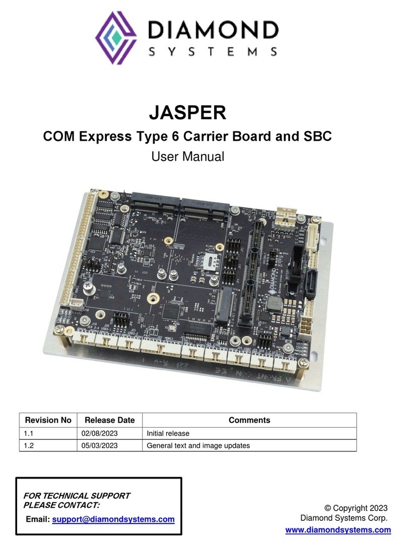
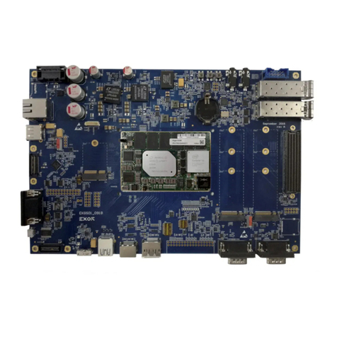
Diamond Systems JETBOX FLOYD-SC Series User manual

JetBox-FloydSC User Manual rev 0.1 www.diamondsystems.com Page 2
Contents
1. Important Safe Handling Information .............................................................................................................4
2. Introduction & System Configurations...........................................................................................................6
JetBox-FloydSC System Overview................................................................................................................6
System Configurations ..................................................................................................................................6
3. Functional Overview.........................................................................................................................................7
Power Supply Specifications.........................................................................................................................7
USB Ports......................................................................................................................................................7
Display...........................................................................................................................................................7
Ethernet Ports................................................................................................................................................7
Serial Ports....................................................................................................................................................7
Digital I/O.......................................................................................................................................................7
4. Block Diagram...................................................................................................................................................8
5. Mechanical Drawing .........................................................................................................................................9
3D STEP Model.............................................................................................................................................9
2D Drawing....................................................................................................................................................9
6. Connectors, LEDs & Jumper Locations...................................................................................................... 10
JetBox-FloydSC Front Panel Call Outs...................................................................................................... 10
FloydSC Carrier board Callouts –TOP...................................................................................................... 11
FloydSC Carrier board Callouts –BOTTOM.............................................................................................. 11
7. Jumper Configuration ................................................................................................................................... 12
Digital I/O Configuration ............................................................................................................................. 12
USB2.0 Top Port Host/Device Selection.................................................................................................... 13
Serial Ports Configuration........................................................................................................................... 13
8. Connector Pinouts......................................................................................................................................... 14
System Front Panel Connectors................................................................................................................. 14
Input Power Connector.................................................................................................................... 14
HDMI Port........................................................................................................................................ 14
Display Port...................................................................................................................................... 14
Ethernet Ports.................................................................................................................................. 15
USB2.0 Ports................................................................................................................................... 15
USB3.0 Port..................................................................................................................................... 15
Serial Ports ...................................................................................................................................... 16
Digital I/O......................................................................................................................................... 16
FloydSC Base Board Connectors............................................................................................................... 16
RTC Battery (J18)............................................................................................................................ 16
Daughter Board Power Feed (J21).................................................................................................. 17
Camera (J15,J16,J20) ..................................................................................................................... 17
M.2 PCIe Connector (J19)............................................................................................................... 18
Daughter Board Expansion Connector (J9)..................................................................................... 19
Controlled Area Network (J14) ........................................................................................................ 20
Fan Connector (J17)........................................................................................................................ 20
Utility Connector (J12)..................................................................................................................... 20
9. I/O Connector List.......................................................................................................................................... 21
JetBox-FloydSC User Manual rev 0.1 www.diamondsystems.com Page 3
10. Digital I/O ........................................................................................................................................................ 22
Digital I/O Specifications............................................................................................................................. 23
. Digital I/O Control Software Commands .................................................................................................. 24
11. Serial Ports..................................................................................................................................................... 25
12. Getting Started............................................................................................................................................... 26
13. System Assembly.......................................................................................................................................... 27
Installing the Jetson Module on FloydSC................................................................................................... 28
Installing FloydSC inside the JetBox.......................................................................................................... 29
14. Reprogramming the Embedded Linux Image............................................................................................. 30
Hardware Setup.......................................................................................................................................... 30
Software Setup........................................................................................................................................... 31
Flashing Jetson Nano Module......................................................................................................... 31
Flashing Jetson Xavier NX Module ................................................................................................. 33
15. Specifications................................................................................................................................................. 35
16. Limited Warranty Policy................................................................................................................................ 36

JetBox-FloydSC User Manual rev 0.1 www.diamondsystems.com Page 4
1. IMPORTANT SAFE HANDLING INFORMATION
WARNING!
ESD-Sensitive Electronic Equipment
Observe ESD-safe handling procedures when working with this product.
Always use this product in a properly grounded work area and wear
appropriate ESD-preventive clothing and/or accessories.
Always store this product in ESD-protective packaging when not in use.
Safe Handling Precautions
Diamond Systems boards are designed with complex circuitry and electronic components that are ESD
(Electrostatic Discharge)-sensitive. This increases the likelihood of the boards incurring accidental damage during
handling, installation, and connection to other equipment.
It is highly recommended that the following precautionary measures and best practices be observed in sequential
order:
•Wear an anti-static Wristband/Strap or/and an antistatic Lab Coat or/and Rubber-soled shoes.
•Spread anti-static mats over the table or work surface or/and anti-static mats on the floor.
•Unpack components and remove them from their anti-static bags only when they are ready to be
used.
•Avoid ungrounded surfaces such as plastic, carpets, floors, or tables, in the work area.
•Handle boards by the edges and their metal mounting brackets. Avoid touching components on the
boards and the edge connectors that connect to expansion slots.
The following information describes common causes of failure found on boards and components returned to
Diamond Systems for repair. It is provided as a guideline to avoid accidental damage.
ESD Damage: This type of damage is typically impossible to detect because there is no visual sign of failure or
damage. In this type of damage, the board eventually stops functioning because of some defective components.
Usually, the failure can be identified, and the chip can be replaced.
To prevent ESD damage, always follow proper ESD-prevention practices when handling computer boards.
Damage During Handling or Storage: Physical damage on boards also occur due to mishandling. A common
observation is that of a screwdriver slipping on the board during installation, causing a gouge on the PCB surface,
cutting signal traces or damaging components.
Another common observation is damaged board corners, indicating the board was dropped. This may or may not
cause damage to the circuitry, depending on components located near the edges. Most Diamond System boards
are designed with a minimum 25 mils clearance between the board edge and component pad. The Ground/power
planes are located a minimum of 20 mils from the edge to avoid possible shorting from this type of damage.
However, these design rules do not prevent damage in all situations.
Sometimes boards are stored in racks with slots that grip the edge of the board. This is a common practice for
board manufacturers. Though Diamond Systems boards are resilient to damages, the components located close
to the board edges can be damaged or even knocked off the board if the board lies tilted in the rack.
Diamond Systems recommends that all its boards be stored only in individual ESD-safe packaging units. If
multiple boards are stored together, they should be contained in bins with dividers placed between the boards. Do
not pile boards on top of each other or cram too many boards within a small location. This can cause damage to
connector pins or fragile components.

JetBox-FloydSC User Manual rev 0.1 www.diamondsystems.com Page 5
Damage During Installation on a PC/104 Stack: Damage on boards can also occur while installing the board in
a PC/104 Stack A common cause of damage occurs when the connector pins are misaligned with their
corresponding interfaces on the stack.
For example, during installation, if a PC/104 board pin-mapping is misaligned/shifted by 1 row or 1 column, it can
cause the 12V power and Ground signal lines on the bus to contact the wrong pins on the board and damage
components linked to the data bus lines.
Bent Connector Pins: This type of problem can be resolved by re-bending the pins to their original shape using
needle-nose pliers.
The most common cause of a bent connector pin is when the board is pulled off a stack by tugging it at angles
from one end of the connector to the other, to release it off the stack. Tugging the board off the stack in this
manner can bend the pin(s) significantly.
A similar situation can occur when pulling a ribbon cable off a pin header. If the pins are bent too severely,
bending them back can cause them to weaken or break. In this case, the connector must be replaced.
Power Damages: There are various causes of power-specific damages that can occur while handling the board.
Some common causes such as –a metal screwdriver tip slipping, or a screw dropping onto the board while it is
powered-up, causes a short between a power pin and a signal pin on a component.
These faults can cause over-voltage/power supply problems besides other causes described below.
To avoid such damages, assembly operations must be performed when the system is powered off.
Power Supply Wired Backwards: Diamond Systems power supplies and boards are not designed to withstand a
reverse power supply connection. This will destroy almost all ICs connected to the power supply. In this case, the
board will likely be irreparable and must be replaced. A chip destroyed by reverse or excessive power will often
have a visible hole or show some deformation on the surface due to vaporization inside the package.
Overvoltage on Digital I/O Line: If a Digital I/O signal is connected to a voltage above the maximum specified
voltage, the digital circuitry can be damaged. The acceptable voltage range, on most Diamond Systems boards
connected to digital I/O signals is 0-5V, with overvoltage protection up to 5.5V (-0.5 to 5.5V). Overvoltage beyond
this limit can damage the circuitry.
Other considerations are Logic Signals, which are typically generated between 12V to 24V.
If a Digital I/O Line of 12V to 24V is connected to a 5V logic chip, the chip will be damaged, and the damage could
extend to other chips in the circuit.
IMPORTANT! Always check power connections twice before powering up!

JetBox-FloydSC User Manual rev 0.1 www.diamondsystems.com Page 6
2. INTRODUCTION & SYSTEM CONFIGURATIONS
JetBox-FloydSC System Overview
JetBox-FloydSC is a compact Nvidia Jetson AI computing platform ready to deploy. It includes the Jetson Nano or
NX module installed on Diamond Systems FLOYDSC carrier board with a Linux OS installed and preconfigured to
support all the I/Os on FloydSC.
The system is available multiple standard module configurations to meet a range of customer needs. The system
installed with NVIDA Jetson Nano module supports only 1x Ethernet interface while the system when installed with
NVIDIA Jetson Xavier NX module supports 2x Ethernet interfaces.
JetBox-FloydSC features 11-position screw terminal on the front panel to access the Digital I/Os available on the
system. The enclosure is DIN rail mountable or can be used in a "tabletop" scenario.
The system is compatible with both 12V and 24V DC power supplies. A 12VDC universal AC adapter is included
with the system.
System Configurations
JetBox-FloydSC utilizes the Floyd-SC BB02 baseboard and is available with three models of Jetson moduls. The
architecture of the modules allows for a CAN port and a 2nd Ethernet port with the Xavier NX module:
Feature
JB-FLDSC-NAO-02
JB-FLDSC-TNX-02
JB-FLDSC-XNX-02
Module supported
Nano
TX2 NX
Xavier NX
Gigabit Ethernet
1
1
2
USB 3.0
1
1
1
USB 2.0
2
2
2
Serial ports
1 RS-232 + 1 RS-232/485
Display
1 HDMI + 1 DP
1 HDMI + 1 DP
1 HDMI + 1 DP
Storage / Expansion
socket
M.2 M-Key 2242 / 2280
dual footprint
M.2 M-Key 2242 / 2280 dual
footprint
M.2 M-Key 2242 / 2280 dual
footprint
GPIO
8x GPIOs with 3.3V/5V
Compatibility
8x GPIOs with 3.3V/5V
Compatibility
8x GPIOs with 3.3V/5V
Compatibility
CAN
N/A
N/A
1 port (replaces 1 serial port
on the front panel)

JetBox-FloydSC User Manual rev 0.1 www.diamondsystems.com Page 7
3. FUNCTIONAL OVERVIEW
Power Supply Specifications
The JetBox-FloydSC accepts a wide input voltage range of +7V to +24V. Maximum power consumption with
either Nano or NX module installed, and all peripherals operating is 35W. The maximum allowable reflected
ripple, measured at the voltage input connector is 50 mV p-p. The input power is provided via a barrel jack with
5.5mm OD / 2.5mm ID dimensions (tip positive).
USB Ports
The JetBox-FloydSC provides 2x USB 2.0 ports and 1x USB 3.0 port.
1. 2x USB 2.0 ports are available on a vertically stacked dual-port USB 2.0 connector.
2. The upper USB 2.0 port (USB0) can be used for programming during recovery mode.
3. 1x USB 3.0 port terminates on an upright right-angle USB 3.0 connector. This connector also supports
the USB 2.0 protocol.
The USB signals connected to upright USB3.0 connector is optionally connected to expansion connector using 0
Ohm resistors.
Display
The JetBox-FloydSC supports two display options:
1. HDMI 2.0a/b video with audio with both Nano and NX modules.
2. DP 1.4 video, audio supported with NX module only.
The HDMI is terminated on an upright HDMI connector & the DP is terminated on a separate upright DP
connector.
Ethernet Ports
The JetBox-FloydSC is equipped with one or two Gigabit Ethernet ports:
1. (all models) A 10/100/1000 Ethernet port routed from the module.
2. (NX model only) A 10/100/1000 Ethernet port derived from the Intel WGI210IT/Intel I210 PCIe Ethernet
controller when used with Xavier/TX2 NX module
Both Ethernet ports are accessed via two RJ-45 jacks. The magnetics needed for these ports are available on the
FloydSC carrier. The jacks indicate Link and speed status associated with each port using integrated LEDs.
When a daughterboard is used for expansion, the second Ethernet interface is unavailable since the PCIe Port 1
is utilized by the Daughterboard.
Serial Ports
The JetBox-FloydSC provides two serial ports, one with jumper selectable RS232 or RS485 protocol modes and
one dedicated RS232. Since the serial ports from module are 1.8V complaint, they are level shifted to 3.3V logic
before feeding to the transceivers.
Digital I/O
The JetBox-FloydSC provides 8x digital I/Os , which are individually configurable as an output or input. The digital
I/Os are realized using an I2C GPIO expander. The I2C control for the expander is directly fed from the module.
This I2C GPIO expander can support both 3.3V and 5V, so a voltage translator is used to between module and
I2C GPIO expander. This expander device is accessible on the I2C address 0x22. The IO voltage is selectable
using jumper setting refer section 9.1 for Jumper configuration details.
The Digital I/Os are made available on a 11-position 3.5mm screw terminal connector.

JetBox-FloydSC User Manual rev 0.1 www.diamondsystems.com Page 8
4. BLOCK DIAGRAM
Below are the Block Diagrams of the JetBox-FloydSC system with Nano module & the Xavier NX modules. There
are two PCIe ports available on the Xavier NX module due to which either an additional Ethernet port can be
supported or the Daughterboard Expansion.
Figure 1 JetBox-FloydSC with Nano module installed & 1x Ethernet port
Figure 2 JetBox-FloydSC with Xavier NX module installed & 2x Ethernet ports

JetBox-FloydSC User Manual rev 0.1 www.diamondsystems.com Page 9
5. MECHANICAL DRAWING
3D STEP Model
The complete product 3D STEP model is available to our customers in the product support page here.
2D Drawing
All dimensions are in mm.
Figure 3 JetBox-FloydSC - Front View
Figure 4 JetBox-FloydSC - Top View

JetBox-FloydSC User Manual rev 0.1 www.diamondsystems.com Page 10
6. CONNECTORS, LEDS & JUMPER LOCATIONS
JetBox-FloydSC Front Panel Call Outs
Figure 5 JetBox-FloydSC - Front Panel Call-Outs
Sl No
Description
1
Power In, 7 –24 VDC
2
Ethernet –1
3
Ethernet –2
4
Reset Switch
5
Recovery Switch
6
HDMI Port
7
DP Port
8
USB2.0
9
Digital I/O
10
USB3.0
11
RS-232
12
RS-232/RS-485

JetBox-FloydSC User Manual rev 0.1 www.diamondsystems.com Page 12
7. JUMPER CONFIGURATION
NOTE: To access the jumpers on the Floyd baseboard, the TOP heat sink plate needs to be removed from the
JetBox-FloydSC system.
The various jumpers for the Jetbox-Floyd provided by the Floyd baseboard are as provided below:
1. JP1: Digital I/O Configuration
2. JP2: USB2.0 Top Port Host/Device Selection
3. JP3: Serial Ports Configuration
Digital I/O Configuration
Jumpers are provided to enable pull-up/down on the Digital I/Os. By default, the DIOs are pulled down. The
configuration is as shown below:
Jumper Position
Configuration
1
Enable 3.3/5V pull-up to DIO Port A
2*
Enable pull-down to DIO Port A
3
Enable 3.3/5V pull-up to DIO Port B
4*
Enable pull-down to DIO Port B
5
Configure DIOs to be 5V compliant
6*
Configure DIOs to be 3.3V
*:- Default
Figure 8 JP1 jumper mount illustrations

JetBox-FloydSC User Manual rev 0.1 www.diamondsystems.com Page 13
USB2.0 Top Port Host/Device Selection
The USB2.0 Top port of the base board is used as a device in the recovery mode to flash the module and is used
as a Host in normal operation. This selection is achieved by changing the jumper positions on JP3 as tabulated
below:
Jumper Position
Configuration
D
Set USB2.0 port 1 Port as Device for Recovery Mode
H*
Set USB2.0 port 1 Port as Host in Normal Mode
*:- Default
Figure 9 JP2 jumper mount illustrations
Serial Ports Configuration
The serial port protocol modes can be set with jumpers or with software. The protocol selection must either be done
with or with software. If both the jumpers & software are used to set the protocol mode, priority is given to software.
The protocol mode selection & termination enable for RS-485 operation mode with jumper is as tabulated below:
Jumper
Position
IN/OUT
Configuration
1
IN
Enable 121E termination for RS-485 mode operation
1
OUT
Disable 121E termination for RS-485 mode operation
2*
IN
Set SER 2 in RS-232
3
IN
Set SER 2 in RS-485
*:- Default

JetBox-FloydSC User Manual rev 0.1 www.diamondsystems.com Page 14
8. CONNECTOR PINOUTS
System Front Panel Connectors
Input Power Connector
The system provides a barrel connector for main input power. The connector has a 2.5mm center pin and is
intended for use with mating connectors with 2.5mm inner diameter and 5.5mm outer diameter.
Input voltage = +7V to +24V
The connections for the power input connector are Tip = +V and Ring = -V.
Connector Part Number: CUI Devices# PJ-202BH
DSC Mating cable: NA
HDMI Port
The HDMI port is terminated on a standard vertical connector. The connector follows standard HDMI pinout.
D2+
1
2
D2 Shield
D2-
3
4
D1+
D1 Shield
5
6
D1-
D0+
7
8
D0 Shield
D0-
9
10
Clock +
Clock Shield
11
12
Clock -
CEC
13
14
No Connect
DDC Clock
15
16
DDC Data
Ground
17
18
+5V
Hot Plug Detect
19
Connector Part No: Foxconn# QJ3119C-WFB1-4F
DSC Mating cable: Standard HDMI cable
Display Port
DP port is terminated on a standard vertical connector. Connector follows standard DP pinouts as below:
D0+
1
2
D0 Shield
D0-
3
4
D1+
D1 Shield
5
6
D1-
D2+
7
8
D2 Shield
D2-
9
10
D3+
D3 Shield
11
12
D3-
No Connect
13
14
No Connect
Aux+
15
16
Ground
Aux-
17
18
Hot Plug Detect
Ground
19
20
+3.3V
Connector Part No: Foxconn# 3VD21203-H7U0-4H
DSC Mating cable: Standard DP cable

JetBox-FloydSC User Manual rev 0.1 www.diamondsystems.com Page 15
Ethernet Ports
The ethernet ports are terminated on standard RJ45 connectors that has integrated LEDs. The connectors follow
standard TIA/EIA 568B pinouts as below:
1
Data A+
Orange/White
2
Data A-
Orange
3
Data B+
Green / White
4
Data C+
Blue
5
Data C-
Blue / White
6
Data B-
Green
7
Data D+
Brown / White
8
Data D-
Brow
Connector Part No: Link-PP#LPJG101AGNL-1
DSC Mating cable: Standard LAN Cat6 cable
USB2.0 Ports
The system hosts two USB 2.0 ports accessible on a vertically stacked standard USB 2.0 Type A socket that uses
standard pinouts as below:
1
+5V
2
D-
3
D+
4
Ground
Connector Part No: Foxconn# UB1112C-8FDH-4F
DSC Mating cable: NA
USB3.0 Port
The system hosts one USB 3.0 ports accessible on an upright standard USB 3.0 socket that uses standard
pinouts as below:
+5V
1
9
SSTX+
D-
2
8
SSTX-
D+
3
7
Ground
Ground
4
6
SSRX+
5
SSRX-
Connector Part No: Foxconn# UEA3119C-4EB1-4H
DSC Mating cable: NA

JetBox-FloydSC User Manual rev 0.1 www.diamondsystems.com Page 16
Serial Ports
The system provides two serial ports. One of the serial ports is dedicated to RS232 protocol and the second port
can be configured to either RS232 or RS485 based on Jumper settings. The pinouts for different protocols are as
follows:
RS-232
RS-485
No Connect
6
1
No Connect
No Connect
6
1
No Connect
RTS
7
2
RX
TX-
7
2
No Connect
CTS
8
3
TX
No Connect
8
3
TX+
No Connect
9
4
No Connect
No Connect
9
4
No Connect
5
Ground
5
Ground
Connector Part No: DB9 Male
DSC Mating cable: Standard DB9 female-to-female cable
Digital I/O
The system provides access to 8 digital I/O pins on the front panel, terminated on a 11-position, 3.5mm pitch
screw terminal connector. These digital I/O signals are configurable to 3.3V/5V configurable via jumper settings.
The pinouts of the connector are as follows:
1
DIO 0
2
DIO 1
3
DIO 2
4
DIO 3
5
DIO 4
6
DIO 5
7
DIO 6
8
DIO 7
9
+3.3V or +5V
10
Ground
11
Ground
Connector Part No: TE# 1-284414-1
DSC Mating cable: NA
FloydSC Base Board Connectors
RTC Battery (J18)
The external battery input is intended for a 3V battery.
The pinouts for the RTC Battery connector are specified below.
1
RTC BAT +
2
Ground
Connector Part No: Molex# 0022035025
DSC Mating cable: 6980524

JetBox-FloydSC User Manual rev 0.1 www.diamondsystems.com Page 17
Daughter Board Power Feed (J21)
The connector is used to feed VIN input voltage from the Base Board to the Daughter Board when additional
power is required for the Daughter Board. The pinouts for the optional Daughter Board Power feed connector are
as shown below:
1
VIN
2
VIN
3
Ground
4
Ground
Connector PN: Molex# 0532610471
Board to Board Cable: Molex# 0151340400
Camera (J15,J16,J20)
The carrier board embeds three identical 15-pin connectors for multiple CSI Camera connectivity. Ribbon cables
are used to directly plug the camera modules.
The pinouts are as specified below:
J15
J16
J14
1
GND_DIG
1
GND_DIG
1
GND_DIG
2
CSI0_D0_N
2
CSI2_D0_N
2
CSI4_D0_N
3
CSI0_D0_P
3
CSI2_D0_P
3
CSI4_D0_P
4
GND_DIG
4
GND_DIG
4
GND_DIG
5
CSI0_D0_N
5
CSI2_D0_N
5
CSI4_D0_N
6
CSI0_D0_P
6
CSI2_D0_P
6
CSI4_D0_P
7
GND_DIG
7
GND_DIG
7
GND_DIG
8
CSI0_CLK_N
8
CSI2_CLK_N
8
CSI4_CLK_N
9
CSI0_CLK_P
9
CSI2_CLK_P
9
CSI4_CLK_P
10
GND_DIG
10
GND_DIG
10
GND_DIG
11
CAM0_PWDN
11
CAM1_PWDN
11
CAM2_PWDN
12
CAM0_MCLK
12
CAM1_MCLK
12
CAM2_MCLK
13
CAM0_I2C_SCL_3P3
13
CAM1_I2C_SCL_3P3
13
CAM2_I2C_SCL_1P8_E
14
CAM0_I2C_SDA_3P3
14
CAM1_I2C_SDA_3P3
14
CAM2_I2C_SDA_1P8_E
15
V_3P3
15
V_3P3
15
V_3P3
Connector Part No: TE# 1-84952-5
Camera supported: Raspberry Pi Camera Board v2 - 8 Megapixels
Mating cable: FFC Cable included with the camera

JetBox-FloydSC User Manual rev 0.1 www.diamondsystems.com Page 18
M.2 PCIe Connector (J19)
The FloydSC carrier board is equipped with an M.2 PCIe SSD M-keyed connector for 2280 0r 2242 sized
modules for storage applications. An M.2 SSD is "keyed" to prevent the insertion of a card connector to an
incompatible socket on the board.
x4 PCIe lane available from module is routed directly to M.2 PCIe connector The pinouts of the connector are as
shown below:
GND
1
2
3.3V
GND
3
4
3.3V
PETn3
5
6
N/C
PETp3
7
8
N/C
GND
9
10
LED1#
PERn3
11
12
3.3V
PERp3
13
14
3.3V
GND
15
16
3.3V
PETn2
17
18
3.3V
PETp2
19
20
N/C
GND
21
22
N/C
PERn2
23
24
N/C
PERp2
25
26
N/C
GND
27
28
N/C
PETn1
29
30
N/C
PETp1
31
32
N/C
GND
33
34
N/C
PERn1
35
36
N/C
PERp1
37
38
N/C
GND
39
40
N/C
PETn0
41
42
N/C
PETp0
43
44
N/C
GND
45
46
N/C
PERn0
47
48
N/C
PERp0
49
50
PERST#
GND
51
52
CLKREQ#
REFCLKN
53
54
PEWake#
REFCLKP
55
56
N/C
GND
57
58
N/C
KEY
N/C
67
68
SUSCLK
PEDET
69
70
3.3V
GND
71
72
3.3V
GND
73
74
3.3V
GND
75
Connector Part No: Amphenol# 10128798-001RLF
DSC Mating cable: NA
Key: M-Key
Supported Add-on Module: M.2 2280 SSD (W 22 mm x L 80 mm) or M.2 2242 SSD (W 22 mm x L 42 mm)

JetBox-FloydSC User Manual rev 0.1 www.diamondsystems.com Page 19
Daughter Board Expansion Connector (J9)
The FloydSC carrier supports additional interfaces using expansion connector for an optional daughter card. The
pinouts of the Daughterboard Expansion connector are as below:
.
Connector Part No: Hirose# FH55-40S-0.5SH
DSC Mating Cable PN: 6971400
1
Hi-Vin
21
USB2_D_P
2
Hi-Vin
22
GND
3
Hi-Vin
23
USB_SS_TX_P
4
Hi-Vin
24
USB_SS_TX_N
5
Hi-Vin
25
GND
6
Hi-Vin
26
USB_SS_RX_P
7
Hi-Vin
27
USB_SS_RX_N
8
Hi-Vin
28
GND
9
PCIe_RST#
29
PCIe_Clockreq#
10
GND
30
DB_PRESENT#
11
PCIe_NX_TX_P
31
GND
12
PCIe_NX_TX_N
32
SDIO CLK
13
GND
33
SDIO D0
14
PCIe_NX_RX_P
34
SDIO D1
15
PCIe_NX_RX_N
35
SDIO D2
16
GND
36
SDIO D3
17
PCIe_NX_CLK_P
37
SDIO CMD
18
PCIe_NX_CLK_N
38
GND
19
GND
39
SDIO Card Detect
20
USB2_D_N
40
PCIe wake

JetBox-FloydSC User Manual rev 0.1 www.diamondsystems.com Page 20
Controlled Area Network (J14)
Floyd SC model (FLDSC-BB02) implements one CAN bus controller port when integrated with Jetson Xavier NX
module. The pinouts of the connector are as given below:
1
Ground
2
CAN Data -
3
CAN Data +
4
Ground
Connector Part No: BM04B-GHS-TBT
DSC Mating cable: 6981182
The CAN cable 6981182 has the near end terminated with the mating connector GHR-04V-S & the far end with a
DB9M. When the cable is used to access the CAN port, the DB9M follows the pinouts as shown below:
Ground
6
1
No Connect
CAN Data+
7
2
CAN Data-
No Connect
8
3
Ground
No Connect
9
4
No Connect
5
No Connect
Fan Connector (J17)
Active thermal solution is not part of the system. However, to support active solutions, carrier board provides the
provision for this with a fan connector. The pinouts for the fan connector are specified below.
1
PWM
2
Tachometer
3
+5V
4
Ground
Connector Part Number: Molex# 0533980471-2
Supported Fan Model: Delta# ASB0305HP-00CP4
Utility Connector (J12)
The carrier board provides access to utility signals on a 2x10 header.
The pinouts for the utility connector are specified below.
+3.3V
1
2
+5V
Force Off 5V
3
4
SPI SS 3P3
Force Recovery 1,8V
5
6
SPI MISO 3P3
Power Button 5V
7
8
SPI CLK 3P3
Reset 1.8V
9
10
SPI MOSI 3P3
Ground
11
12
GND
Debug UART RX 3.3V
13
14
I2C CLK 3P3
Debug UART TX 3,3V
15
16
I2C DATA 3P3
Ground
17
18
Ground
Ground
19
20
Ground
Connector Part No: 220-97-36GB01
Connector type: 2x10, 2 mm Header
This manual suits for next models
3
Table of contents
Other Diamond Systems Carrier Board manuals

Diamond Systems
Diamond Systems OSBOURNE User manual

Diamond Systems
Diamond Systems FLOYD FLD-BB01 User manual

Diamond Systems
Diamond Systems ELTON ELT-BB01 User manual

Diamond Systems
Diamond Systems Ziggy User manual

Diamond Systems
Diamond Systems Jackson JAX-BB01 User manual

Diamond Systems
Diamond Systems JASPER User manual