FLOYD User Manual rev 1.09 www.diamondsystems.com Page 2
Contents
1.
Important Safe Handling Information ............................................................................................................ 4
2.
Introduction...................................................................................................................................................... 6
Floyd Carrier Board Overview...................................................................................................................... 6
Floyd Carrier Board Models.......................................................................................................................... 7
3.
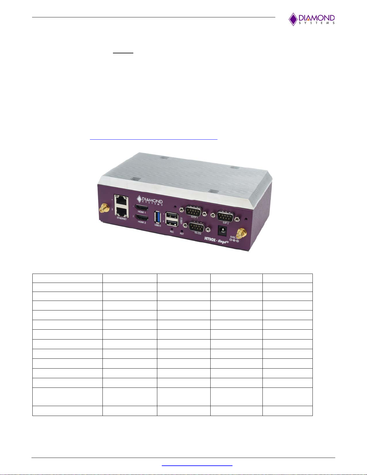
JetBox Floyd System ...................................................................................................................................... 8
4.
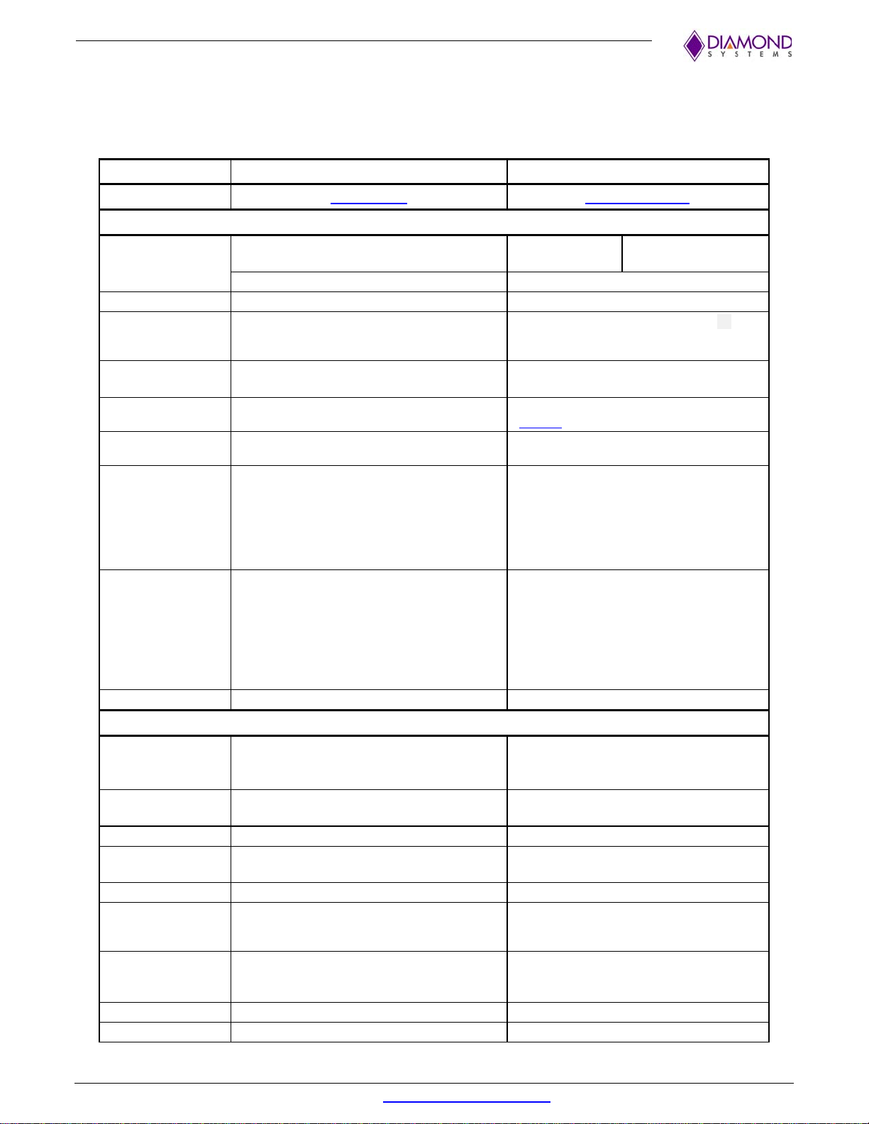
Jetson Module Technical Specifications ...................................................................................................... 9
5.
Functional Overview...................................................................................................................................... 11
Power Supply Specifications...................................................................................................................... 11
Camera Serial Interface (CSI) .................................................................................................................... 11
Controller Area Network (CAN).................................................................................................................. 11
Digital I/O.................................................................................................................................................... 11
Display........................................................................................................................................................ 11
Ethernet Ports............................................................................................................................................. 12
PoE (Power over Ethernet)......................................................................................................................... 12
Audio Interface............................................................................................................................................ 12
LED Indicators............................................................................................................................................ 12
Micro SD Socket......................................................................................................................................... 12
PCIe Link Routing Map............................................................................................................................... 13
PCIe M.2 SSD Socket ................................................................................................................................ 13
PCIe MiniCard Socket ................................................................................................................................ 13
Serial Port Interfaces.................................................................................................................................. 14
USB Ports................................................................................................................................................... 14
Utility Header Connector ............................................................................................................................ 14
6.
Block Diagram................................................................................................................................................ 15
7.
Connector and Jumper Locations ............................................................................................................... 17
Main Component Locations........................................................................................................................ 17
I/O Connectors, Jumpers and Led Specifications...................................................................................... 18
Front-Facing Connectors............................................................................................................................ 19
Expansion Slot and Switch Locations ........................................................................................................ 20
8.
I/O Connectors............................................................................................................................................... 21
Power In Connector: J3.............................................................................................................................. 21
PoE Power-In Connector: J34 (FLD-BB01 only)........................................................................................ 21
RTC Battery Connector: J15 ...................................................................................................................... 21
Camera Connectors: J12, J13, J14............................................................................................................ 22
Controller Area Network (CAN) Connector: J11 (FLD-BB01 Only)............................................................ 23
Ethernet Connectors: J7............................................................................................................................. 23
HDMI Connector: J5................................................................................................................................... 23
USB 2.0 Port Connector: J4....................................................................................................................... 24
USB 3.0 Port Connector: J6....................................................................................................................... 24
Micro SD Connector: J18 ........................................................................................................................... 24
PCIe M.2 SSD Socket (M-KEY) Connector: J19........................................................................................ 25
PCIe Mini Card Connector: J17 (FLD-BB01 only)...................................................................................... 26
Serial Port and GPIO Connectors: J1, J9................................................................................................... 27