Scaime Epsiload 2I/SW User manual

1/7 161708-A_NU-EPSILOAD-2ISW-E-1111_006097
/
SCAIME S.A.S. - BP 501 - F-74105 ANNEMASSE Cedex
Tel. : +33 (0)4 50 87 78 64 - Fax : +33 (0)4 50 87 78 46
Onboard weighing system
Epsiload
2I/SW
3I/SW
MOUNTING INSTRUCTIONS
The technical specifications given in this issue are only indicative and can be modified at any time

2/7 161708-A_NU-EPSILOAD-2ISW-E-1111_006097
/
SUMMARY
SUMMARY............................................................................................................. 2
COMPONENTS...................................................................................................... 3
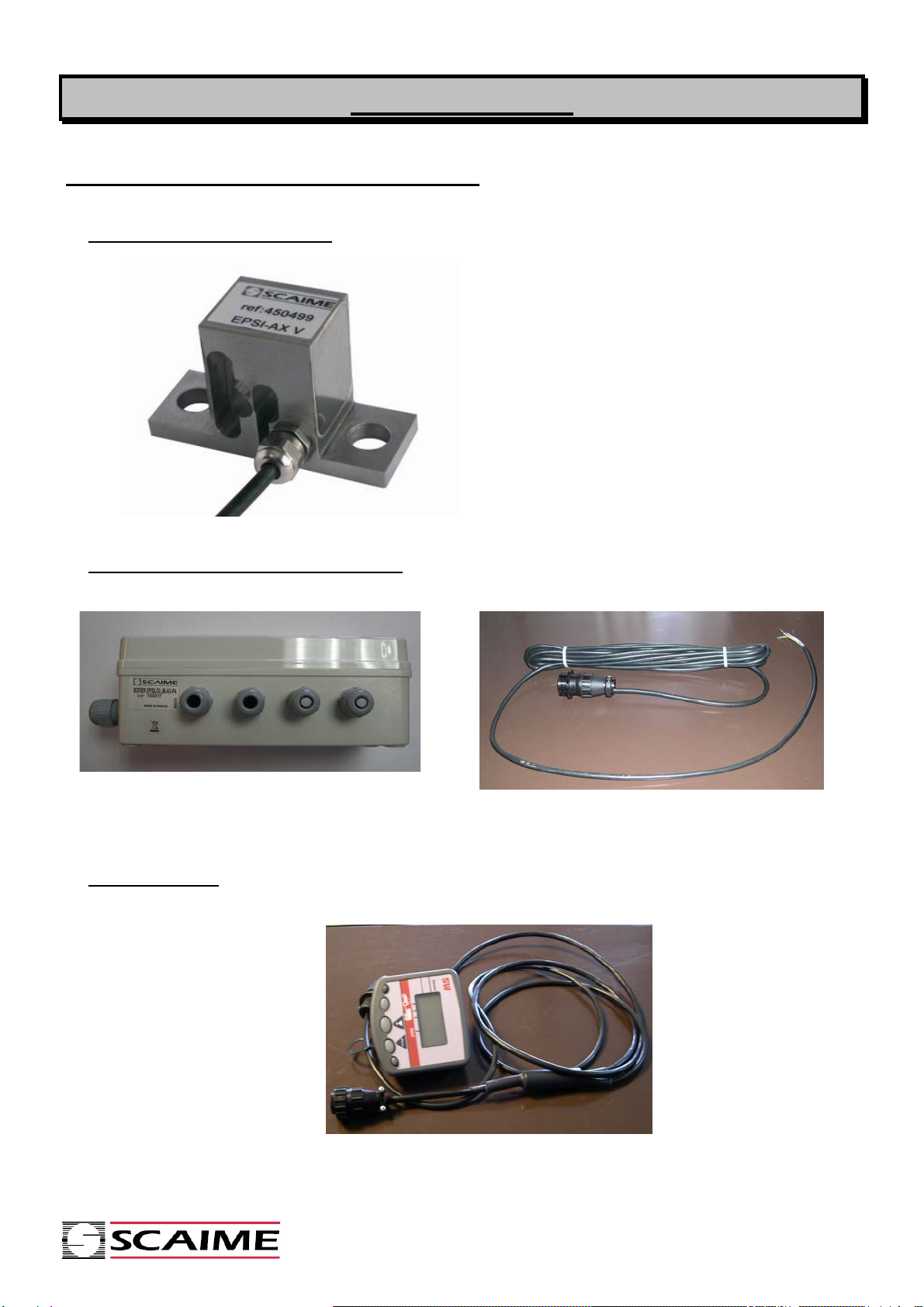
I. TO BE INSTALLED ON THE TRAILER :.................................................................................3
1. EPSI-AX Extensometer :...............................................................................................................3
2 jUnction BOX EPSILOG JB AX P4 :...............................................................................................3
2 Display SW :...................................................................................................................................3
II. REQUIRED MATERIAL FOR INSTALLATION :................................................................................4
1. Option :..........................................................................................................................................4
2. TOOLS to be forecast for insatllations : ........................................................................................4
INSTALLATION AND WIRING.............................................................................. 5
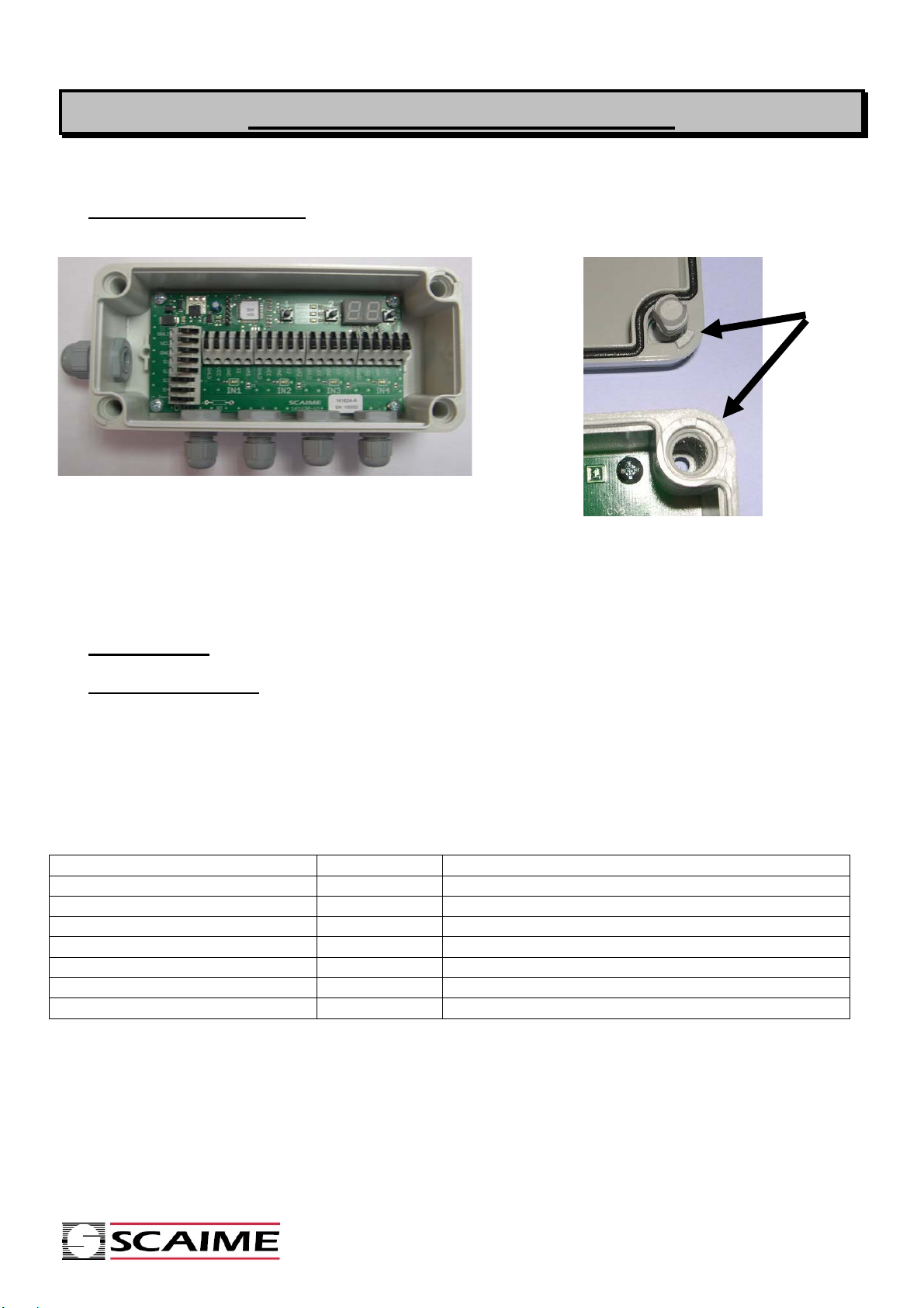
1MOUNTING OF THE BOX : ..........................................................................................5
2WIRING:........................................................................................................................5
1. To the display :..............................................................................................................................5
2. Sensor wiring :...............................................................................................................................6
SENSOR MOUNTING............................................................................................ 7
WARNING :.............................................................................................................................7
SW DISPAY UTILISATION.................................................................................... 7
DISMOUNTING...................................................................................................... 7
Others products and accessories described in this manual are available at SCAIME. You may
download the datasheet from SCAIME website web at www.scaime.com
Revision table
version date Description
A 11/2011
-First issue 161708 ( English version)
-
-
-

3/7 161708-A_NU-EPSILOAD-2ISW-E-1111_006097
/
COMPONENTS
I. TO BE INSTALLED ON THE TRAILER :
1. EPSI-AX EXTENSOMETER :
2 JUNCTION BOX EPSILOG JB AX P4 :
EPSILOG JB AX P4 (ref 850379) Cord set to the SW display (ref 850375)
2 DISPLAY SW :
Display (ref 642047)
2,3 or 4 extensometers according
to the trailer type (ref 450499)
Check the Epsi-
A
X datasheet for
mounting of the sensors

4/7 161708-A_NU-EPSILOAD-2ISW-E-1111_006097
/
II. REQUIRED MATERIAL FOR INSTALLATION :
1. OPTION :
This welding spacer allows to get a perfect flat surface and also a well defined 50mm distance between
M8 threaded holes in order to mount EPSI AX properly. It is recommended to use it on retrofit structure
when M8 holes can not be machined in situ.
Welding parts (ref 850380)
Two CHC M8x12 screw furnished
One welding parts per sensor.
To be welded on the structure to be measured
( axle, draw bar…)
2. NECESSARY TOLLS FOR INSTALLATION :
•1 Dynamometer Spanner (40 mN).
•Two CHC M8 x 12 screws per extensometer. ( only if the part 850380 is not furnished)
•One drilling tool φ=3.2 mm + a threading tool M4.
•4 screws M4 to fix the box Epsilog JB AX P4 on the trailer.

5/7 161708-A_NU-EPSILOAD-2ISW-E-1111_006097
/
INSTALLATION AND WIRING.
1 BOX MOUNTING :
The junction box is mounted by 4 screws M4
under the cover.
Spacing 150x60 mm
Be Careful : The cover is not symmetrical
Check the position of the marking boss
2 WIRING:
1. TO THE DISPLAY :
•Use the cord set 850375 from the junction box to the display
•Pass the stripped wires through the cable gland on the box .
•Connect the wires according to the following table (to connect the wire, Press down the
lever.)
•Tighten the cable gland.
Colours Designation Function
Green/yellow SHLD Shielding
Brown VCC + Excitation
Green GND 0 V
Yellow S1 Signal sensor 1 (draw bar)
White S2 Signal sensor 2 (Front axle)
Pink S3 Signal sensor 3 (Rear axle if two axles)
Grey S4 Signal sensor 4 (if 4 sensors)

6/7 161708-A_NU-EPSILOAD-2ISW-E-1111_006097
/
2. SENSOR WIRING :
•For an installation with 3 or 4 sensors, remove the cap(s)on the cable gland.
•For each sensor, pass the wires through the cable gland.
•Wire the sensors according to the following table :
Wire sensor 1 (draw bar ) on IN1
Wire sensor 2 (front axle ) on IN2
Wire sensor 3 (rear axle ) on IN3
Wire sensor 4 on IN4
•To connect the wires, Press down the levers.
•Tight the cable glands.
Colours Designation Function
Yellow/green SHLD Shielding
Red VCC + Excitation
Black GND 0V
White Si Sensor signal
Blue I out Not Connected (To be insulated)

7/7 161708-A_NU-EPSILOAD-2ISW-E-1111_006097
/
SENSOR MOUNTING
•Mount each sensor onto its support without tighting screws.
•Connect the 16 points circular connector from the cord set 850375 to the SW display.
•Connect the display to the battery using the COBO connector
•The Epsilog junction box is now under voltage. The LED 7 segments display shows a voltage.
•Check that all sensors signal are about 2.5V for a standard extensometer ( use EPSI JB AX
manual)
•Tight each screw until 40Nm. ( Follow Epsi AX instruction manual for tightening)
•The signal must be kept within 0.5 to 4.5 Volts after tightening.
•Tune the offset of each sensor ( cf EPSILOG JB-AX P4 user manual) :
Sensor used in traction: 1 V
Sensor used in compression 4V
Sensor used in traction/compression: 2.5V
BE CAREFUL: Sensors are powered as soon as the COBO connector is plugged to the battery
even if the SW display is switched off . Disconnect the COBO connector from the battery as soon
as any intervention on the box is necessary.
WARNING :
Non exact following of this above procedure may result in malfunctioning of the system.
SW DISPAY UTILISATION
C.f. EPSILOAD SW user Manuel
DISMOUNTING
To dismount EPSI AX extensometer:
•Disconnect the COBO connector so that the system is not under voltage.
•Disconnect the wires of the sensor from the junction box by lifting the levers.
•Untight the M8 screws and dismount them to remove the sensor.
This manual suits for next models
1
Table of contents
Other Scaime Accessories manuals
Popular Accessories manuals by other brands

Tobii Pro
Tobii Pro Nano user manual

BLAUBERG Ventilatoren
BLAUBERG Ventilatoren SGR-3/1 quick start guide

ON Semiconductor
ON Semiconductor AR0331 Series General description

IFM
IFM Efector 500 PI2652 operating instructions

Vestax
Vestax VAI-40 owner's manual

Atlantic Ultraviolet
Atlantic Ultraviolet Sanidyne PLUS+ owner's manual